Table of Contents
Advertisement
Quick Links
PREZONE2
Installation & Operation Guide
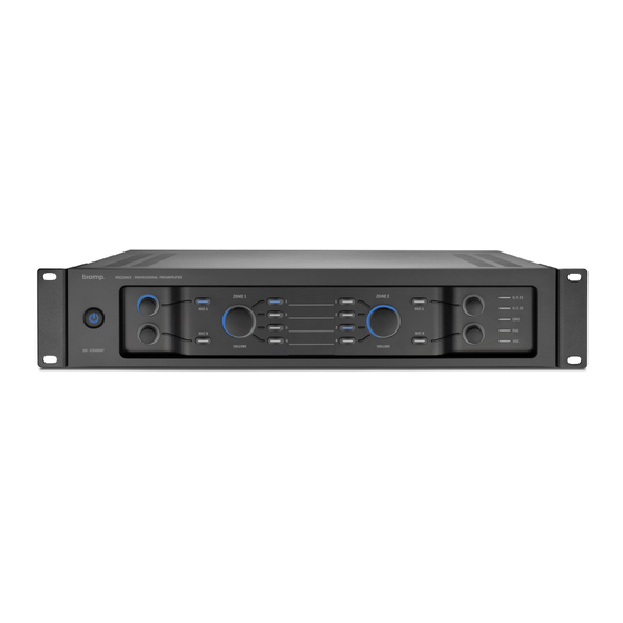
PRODUCT DESCRIPTION
The PREZONE2 is a professional audio device designed to accept audio signals
from multiple sources and supply two distinct zones of audio outputs from these
sources. The device may be controlled from the front panel user interface, wall
control panels, Ethernet capable devices with a web browser, or an external
control system using RS232.
FEATURES
• Emergency Input
• 2 Mono Mic/Line Inputs
• 2 Stereo Output Zones
• 2 Zone Selective Paging Input with Chime
• 4 Stereo Line Inputs
• Wall Panel Control
• Auto Standby
• Ethernet and RS232
• Control Priority Output
• Includes Adhesive Labels for Zone & Source Identification
• Webapp Control
• CE marked, UL listed and RoHS compliant
A:
9300 S.W. Gemini Drive Beaverton, OR 97008 USA
IMPORTANT SAFETY / COMPLIANCE INFO
Class 2 wiring: to reduce the risk of electric shock, the external wiring
connected to the terminals marked with "class 2 wiring" requires installation
of class 2 wiring by an authorized/trained person or by using ready-made leads
or cords.
This unit has NOT been designed for use in mobile applications, such as:
mobile discobars, mobile PA systems, live bands and audio rental systems.
Using it in such applications will lead to product damage and safety risks.
Do not remove or defeat the ground prong on the power cord, as this will
constitute a shock hazard. Equipment should be connected to a mains
socket outlet with a protective earthing connection. This plug is the main
disconnecting device and should remain readily operable. There are no user
interchangeable parts. Please contact Biamp Technical Support or your local
distributor for all service requirements.
Further safety and compliance information may be found at:
www.biamp.com/compliance
Warranty information may be found at:
www.biamp.com/legal/warranty-information
W:
www.biamp.com
Advertisement
Table of Contents

Subscribe to Our Youtube Channel
Related Manuals for Biamp PREZONE2


Summary of Contents for Biamp PREZONE2
- Page 1 PRODUCT DESCRIPTION IMPORTANT SAFETY / COMPLIANCE INFO The PREZONE2 is a professional audio device designed to accept audio signals Class 2 wiring: to reduce the risk of electric shock, the external wiring from multiple sources and supply two distinct zones of audio outputs from these connected to the terminals marked with “class 2 wiring”...
- Page 2 5. Zone 2 Volume Control Rotary volume controls and mute button for microphones A/B in Zone 2 The PREZONE2 front panel features a power/standby button, controls for two distinct zones of audio outputs and an array of LEDs that give status of 6.
- Page 3 PREZONE2 BACK PANEL PREZONE2 Back Panel Connections 3. MIC A Input MIC A input has the 3rd highest* priority of all inputs. The input connection The back panel features numerous inputs and outputs as well as equalizers for accepts a balanced microphone or line level audio signal via the Euroblock both zones, connections for wall controllers, Ethernet and RS232.
-
Page 4: Installation And Connections
13. RS232 The input connection accepts a balanced microphone or line level audio signal 3-Pin Euroblock connector that allows the PREZONE2 to be controlled from an via the Euroblock connector and a stereo line level via RCA connectors. external device. - Page 5 Wiring - MICPAT-2 & MICPAT-D to Paging Mic Input Wiring - Emergency Input If connecting a MICPAT-2 paging station to a PREZONE2, users may send 1. See Figure 2. Connect a balanced 0 dBV paging messages to both zones, either together or independently.
- Page 6 Mono may be selected. the front panel. 2. LO and HI tone controls may be adjusted via EQ knobs for either zone. Figure 7. Zone Outputs & EQ Figure 5. Mic A & B page 6 Installation and Operation Guide PREZONE2...
-
Page 7: Wiring - Ethernet
Zones 1 and/or 2, as required. 1. The PREZONE2 is compatible with the D-DIWAC and DIWAC wall controls. Connect wall controls from the appropriate zones via 2. These signals will become active when connectors on the back panel as shown in Figure 8. -
Page 8: Network Connections
The PREZONE2 will automatically obtain an IP address and configure. In a Manual Standby Mode routed network, the PREZONE2 will obtain an IP address via DHCP. In a switch network or direct connection to a controlling device, the PREZONE2 will auto- If auto standby is set to DISABLED on the back panel, push the on/standby button to enter standby mode. -
Page 9: Network Diagrams
IP address. Figure 12. WiFi Connection via Router Figure 13 shows a direct connection from the PREZONE2 to a PC via Ethernet. This connection does not require any manual IP settings (link-local - both devices auto negotiate). -
Page 10: Control Page
PREZONE2 Webapp 1. Zone Selection Tabs Once the PREZONE2 is connected to a network and is accessible via PC or The zone selection tabs enable control of either Zone 1 or 2. Both zone mobile device, the webapp may be used to control features and functions of the tabs have controls for mic volume, source selection and volume and give PREZONE2.The primary components of the webapp are the control page and... -
Page 11: Settings Page
NOTE: A factory reset may also accomplished via RS232 command and a button sequence. See Factory Reset for more information. Factory Reset Resetting the PREZONE2 to its factory default settings may be accomplished via the webapp as described previously, an RS232 command, or by the button sequence that follows: Power on the device while holding the following buttons: •... - Page 12 RS232 Control Figure 16 gives possible text commands. By following the connections from the The RS232 control port allows controlling the PREZONE2 via an external device left to right, valid commands may be created. using text command protocol. The protocol uses SET and GET as the first part of the command structure. SET may be used to change values in the device while GET may be used to gather information about the device.
- Page 13 PREZONE2 Block Diagram Figure 17, below gives a signal flow block diagram of the PREZONE2. The key at the bottom right shows which blocks are located on the front and back panels, respectively. Figure 17. Signal Flow Diagram page 13...
- Page 14 However, due to ongoing technical advances, changes or modifications may have occurred that are not covered in this manual. The latest version is available at www.biamp.com. 9300 S.W. Gemini Drive Beaverton, OR 97008 USA www.biamp.com...
Need help?
Do you have a question about the PREZONE2 and is the answer not in the manual?
Questions and answers