Table of Contents
Advertisement
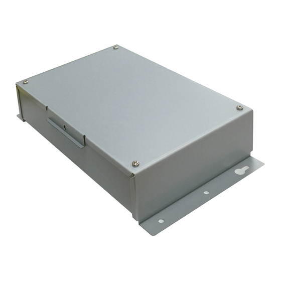
UTY-VKGX
INSTALLATION MANUAL
KNX CONVERTOR FOR VRF
For authorized service personnel only.
INSTALLATIONSANLEITUNG
KNX-KONVERTER FÜR VRF
Nur für autorisiertes Fachpersonal.
MANUEL D'INSTALLATION
CONVERTISSEUR KNX POUR VRF
Pour le personnel agréé uniquement.
MANUAL DE INSTALACIÓN
CONVERTIDOR KNX PARA VRF
Únicamente para personal de servicio autorizado.
MANUALE DI INSTALLAZIONE
CONVERTITORE KNX PER VRF
A uso esclusivo del personale tecnico autorizzato.
ΕΓΧΕΙΡΙΔΙΟ ΕΓΚΑΤΑΣΤΑΣΗΣ
ΜΕΤΑΤΡΟΠΕΑΣ KNX ΓΙΑ VRF
Μόνο για εξουσιοδοτημένο τεχνικό προσωπικό.
MANUAL DE INSTALAÇÃO
CONVERSOR KNX PARA VRF
Apenas para técnicos autorizados.
РУКОВОДСТВО ПО УСТАНОВКЕ
КОНВЕРТОР KNX ДЛЯ СИСТЕМЫ VRF
Только для авторизованного обслуживающего персонала.
MONTAJ KILAVUZU
VRF IÇIN KNX DÖNÜŞTÜRÜCÜ
Yalnızca yetkili servis personeli için.
VRF 系统用 KNX 信号转换器
仅针对授权的专业维修人员。
安装说明书
安装说明书
[Original instructions]
PART NO. 9374707164-02
Advertisement
Table of Contents

Related Manuals for Fujitsu AIRSTAGE UTY-VKGX


Summary of Contents for Fujitsu AIRSTAGE UTY-VKGX
- Page 1 INSTALLATION MANUAL KNX CONVERTOR FOR VRF For authorized service personnel only. INSTALLATIONSANLEITUNG KNX-KONVERTER FÜR VRF Nur für autorisiertes Fachpersonal. MANUEL D’INSTALLATION CONVERTISSEUR KNX POUR VRF Pour le personnel agréé uniquement. MANUAL DE INSTALACIÓN CONVERTIDOR KNX PARA VRF Únicamente para personal de servicio autorizado. UTY-VKGX MANUALE DI INSTALLAZIONE CONVERTITORE KNX PER VRF...
-
Page 2: Table Of Contents
This mark indicates procedures which, if improp- starting installation work. WARNING erly performed, might lead to the death or serious http://www.fujitsu-general.com/global/support/ injury of the user. The following installation parts are supplied. Use them as required. Each terminal marked with (Protective earth mark) shall be securely Name and Shape Q’ty... -
Page 3: Electrical Requirement
3. ELECTRICAL REQUIREMENT 5. WIRING Size Wire type Remarks WARNING 1Ø AC220–240 V 1.25 mm Before starting installation work, turn off the power of this unit and the Maximum Power 50/60Hz, 2 Cable + (16AWG) Type 60245 IEC connection destination. Do not turn on the power again until installation supply earth (ground) 57 or equivalent... -
Page 4: Wiring Method
ELECTRICAL WIRING 5.1. Wiring method 1Ø 50/60 Hz 220-240 V PROPER SYSTEM DIAGRAM General-purpose INDOOR UNIT KNX device BREAKER KNX CABLE EARTH (Twisted pair) General-purpose POWER KNX device Lighting facilities SUPPLY CABLE TRANSMISSION CABLE Security system KNX Network Automatic fi re TRANSMISSION alarm interface OUTDOOR UNIT... -
Page 5: Installing The Knx Convertor
5.2.3. KNX cable 15 mm Ring terminal (9/16 in) (3/16 in) Sleeve KNX connector Screw with special Screw with washer special washer Ring terminal Ring 6. INSTALLING THE KNX CONVERTOR Cable terminal Cable WARNING Always use the accessories and specifi ed installation work parts. Check the state of the installation parts. -
Page 6: Connecting The Power Supply Cable
Cable tie * 6.1. Connecting the power supply cable (Accessories) Dust proof bushing (1) Remove the 4 screws (M4 × 6 mm), and then remove the cover of main unit. The screw hole Screws Power supply cable Cable tie (Accessories) (2) As shown in the illustration below, remove the two screws (M4×6mm), and remove the cover. -
Page 7: Connecting The Transmission Cables
6.2. Connecting the transmission cables 7. CIRCUIT BOARD SETTING (1) Turn the power off. Set this product rotary switch SET1 and DIP switch SET2, Prog Button. (2) Make a hole in the center of the dust proof bushing using a driver. (3) Pass the transmission cable and the KNX cable through the hole of dust proof bushing and pull it into the body. -
Page 8: Turning On The Power
8. TURNING ON THE POWER 10. USB CABLE CONNECTION Connect the accessory USB cable to the terminal below. CAUTION Check that the power supply voltage is within the specifi ed range. If the power supply voltage outside the specifi cation is input, it will cause trouble. -
Page 9: Led Display
12.2. Error code 12. LED DISPLAY For the error indications of devices connected to the convertor, refer to 12.1. Normal code each manual. Error indications Normal indications Error contents LED1 LED2 LED3 Normal contents LED1 LED2 LED3 LED4 (green) (orange) (red) (green) (orange)
Need help?
Do you have a question about the AIRSTAGE UTY-VKGX and is the answer not in the manual?
Questions and answers