Table of Contents
Advertisement
Quick Links
Installation Instruction – SW3-935
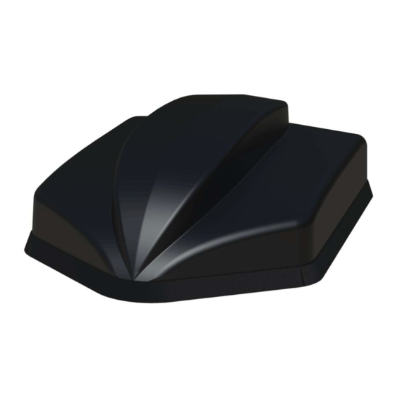
MiMo UHF / 4G/5G Sharkfi n Antenna
A.
Introduction
The GPSDS[X]/SHK[G]S[X]/FINDS[X] series is multi-function antenna with 2x2 MiMo function
for 4G and 3.6GHz 5G LTE, 2x2 UHF LTE function in banded variants from 380-470MHz and
incorporates up to two active GPS/GNSS antenna with 26dB gain LNAs. The GPSD version has
a M6 stud (under a blanking cover) for an optional comms whip. In addition, versions are available
which include 2x2, 3x3 or 4x4 MiMo dual band WiFi antennas.
This antenna is suitable for fi tment to vehicle panels of up to 8mm (0.31"). Heat shrink tubes
are included in the kit, to enable the coaxial connections to be sealed as an extra precaution if
required.
Electrical Safety Note
The GPSD, SHK[G] variants contain an active GPS/GNSS antenna.Rated voltage: 3-5VDC Rated current: 20mA maximum
The supply to this device must be provided with overcurrent protection of 1A maximum.
B.
Mounting requirements and selecting location
For optimum performance, it is recommended that the antenna is fi tted on a conductive (metal) panel. For GPSD version, if a whip will not be
fi tted, and for SHK[G] and FIND types, it is possible to mount the antenna on a non-conductive panel with acceptable performance for all the
antenna functions. For GPSD type, if a whip is to be used, then the antenna must be fi tted on a conductive ground plane - recommended size
is ½ wave length diameter at the lowest frequency of whip operation. To calculate this size, use formula below:
When fi tting on a non-metallic panel, if a whip is being used a ground plane plate of suitable size should be fabricated and fi tted under the
mounting panel; the earthing washer must make low resistance electrical contact with this plate (<0.2Ω).Select a mounting location, checking
for roof curvature to ensure that the antenna base will have a fl at mounting surface. The antenna should be located as far as possible from
surrounding roof mounted items (e.g light bar, air con unit). Ensure that there is adequate under panel clearance and that there is no double
skin panel or cross brace present. Measure to check for central position if applicable.
Important Note Regarding Sealing
In order to ensure that the installation is properly sealed against the mounting surface care must be taken regarding curvature
of the mounting panel. It is highly recommended to install the antenna on a clean, fl at and level surface. After installation the
compression of the rubber boot against the mounting panel should be checked and a small bead of neutral cure silicone sealant
can be applied around the periphery of the mounting boot if requried. For the GPSD variants if a whip is not being used or is
removed for a carwash then the blanking cap should be fi tted.
C.
Prepare and drill hole
Hole
∅19
D.
Fitting the antenna
Remove protective backing from underside of antenna, feed coaxial cables through panel. Position the antenna over the hole ensuring correct
orientation and stick to panel by applying fi rm downward pressure, allow the boot to fully compress against the mounting panel.
Caution – A slotted/split nut is provided in order to simplify fi tting it over the coaxial cables. When fi tting the nut, it is important to ensure that
the cables are held centrally whilst the nut is correctly started on the threads. The nut should fi t freely by hand and only require a fi nal tighten
by spanner.
Assemble the nut and washer from underside and tighten to recommended torque of 5Nm (3.6 ft/lbs).
Remove blanking cap and screw comms antenna whip securely to mounting stud (where used).
150 / frequency in MHz = ½ wavelength (m)
Examples: 150MHz =100cm (39.4"); 400MHz = 38cm (15"); 900MHz =16cms (6.3").
Mask panel area around hole position to protect paintwork and headliner. Drill a pilot hole, and then
increase to 19mm (3/4"), ensuring that drill/cutter bit does not contact headliner. Clean area around
the hole, carefully removing all swarf.
Remove paint and primer from under panel surface to ensure adequate earth contact by washer and
nut. Apply some petroleum jelly or paint around the hole to prevent corrosion.
Fig.1
SW3-935 V1
Advertisement
Table of Contents

Subscribe to Our Youtube Channel
Related Manuals for Panorama Antennas SW3-935


![Antenna Panorama Antennas LP[G]AM Series Installation Instructions](https://static-data2.manualslib.com/product-images/45e/3211865/60x60/panorama-antennas-lp-g-am-series-antenna.jpg)

![Antenna Panorama Antennas L[G]M[X] Series Installation Instructions](https://static-data2.manualslib.com/product-images/38c/3285221/60x60/panorama-antennas-l-g-m-x-series-antenna.jpg)


Summary of Contents for Panorama Antennas SW3-935
- Page 1 Installation Instruction – SW3-935 MiMo UHF / 4G/5G Sharkfi n Antenna SW3-935 V1 Introduction The GPSDS[X]/SHK[G]S[X]/FINDS[X] series is multi-function antenna with 2x2 MiMo function for 4G and 3.6GHz 5G LTE, 2x2 UHF LTE function in banded variants from 380-470MHz and incorporates up to two active GPS/GNSS antenna with 26dB gain LNAs.
- Page 2 MiMo UHF / 4G/5G Sharkfi n with GNSS Antenna Manufacturer: Panorama Antennas Ltd 61 Frogmore, London, SW18 1HF, U.K. This declaration is issued under the sole responsibility of the manufacturer The object of the declaration described above is in conformity with the relevant Union Harmonization Legislation below:...
Need help?
Do you have a question about the SW3-935 and is the answer not in the manual?
Questions and answers