Advertisement
Quick Links
Installation Instruction – SW3-772
CM[X]-24-58-2[VAR] Series
A.
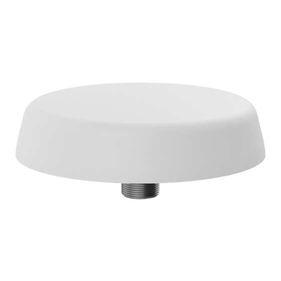
Introduction
The CM[X]-24-58 range has been designed to provide MiMo dual
band WiFi coverage in an ultra low profile package. The compact,
robust low-profile housing contains up to four antenna elements
with effective isolation and low correlation covering 2.4-2.5/4.9-
6GHz.
The antenna is designed to be ceiling mounted and can be fitted
on a conductive or non-conductive panel. Supplied with integral
flame retardant CS32 cables (Compliant to UNECE 118 and
EN45545-2) and a halogen free flame retardant radome, the
antenna is suitable for many environments.
B.
Select a suitable mounting location:
The antenna is omni-directional and should be mounted as centrally as possible within the desired
coverage area. The roof space should be accessible at this location to permit routing of cables to the
wireless device.
Select a flat level location on the desired ceiling which is free from obstructions and not close to other
ceiling mounted items. Consider downward projection of antenna and any height clearance issues
with low ceilings.
Safety Note
Take care to avoid mounting the antenna in close proximity to metal ceiling furniture such
as girders, joists and air conditioning units as these objects may affect the antenna's
performance.
C.
Mount the Antenna
Hole
19mm
or
26mm
D.
Routing and terminating coaxial cable(s)
Route the coaxial cables to the wireless device, taking care to avoid running adjacent to existing wiring or ceiling
furniture. Fit coaxial connectors or adapters if necessary. The CM[X]-24-58 antenna range incorporates identical
and equidistant elements around the housing and it doesn't matter what order the cables are connected to the
MiMO (2x2/3x3/4x4) access point.
If the ceiling is constructed with removable ceiling tiles, it may be best to
remove the tile, mount the antenna, and then re-fit.
Mark the centre position of the antenna location and make a 19mm (3/4")
hole or a 26mm (1.02") hole (if the antenna is a version fitted with N type
connectors).
Remove the adhesive pad backing and place the antenna in position.
Fit washer and nut - tighten to 4Nm. If mounting to a 26mm (1.02") hole make
sure the antenna is centered in the hole if possible.
SW3-772 - Document Version 3
Advertisement

Subscribe to Our Youtube Channel
Related Manuals for Panorama Antennas SW3-772 CM(X)-24-58-2(VAR) Series


![Antenna Panorama Antennas LP[G]AM Series Installation Instructions](https://static-data2.manualslib.com/product-images/45e/3211865/60x60/panorama-antennas-lp-g-am-series-antenna.jpg)

![Antenna Panorama Antennas L[G]M[X] Series Installation Instructions](https://static-data2.manualslib.com/product-images/38c/3285221/60x60/panorama-antennas-l-g-m-x-series-antenna.jpg)


Summary of Contents for Panorama Antennas SW3-772 CM(X)-24-58-2(VAR) Series
- Page 1 Installation Instruction – SW3-772 CM[X]-24-58-2[VAR] Series SW3-772 - Document Version 3 Introduction The CM[X]-24-58 range has been designed to provide MiMo dual band WiFi coverage in an ultra low profile package. The compact, robust low-profile housing contains up to four antenna elements with effective isolation and low correlation covering 2.4-2.5/4.9- 6GHz.
- Page 2 Commission and test Using a suitable antenna analyser, carry out a VSWR test in each freq. band. The VSWR should comply with values shown in the data sheet. Connect the antenna to the coaxial cable and carry out a system check. Notices European Waste Electronic Equipment Directive 2002/96/EC Please ensure that your old Waste Electricals and Electronics are recycled.
Need help?
Do you have a question about the SW3-772 CM(X)-24-58-2(VAR) Series and is the answer not in the manual?
Questions and answers