Advertisement
Installation Instructions – SW3-606
GPSB Series
A.
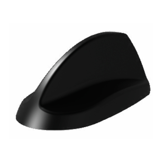
Introduction
The GPSB series is a high performance combination quad function
antenna in an OEM style shark fin housing. The antenna has an active
GPS antenna with a 26dB gain LNA suitable for 3 to 5 volt supply via
the GPS coax cable.The GPSB is suitable for fitment to standard vehicle
panels of up to 4mm (0.16") thickness.
Heat shrink tubes are included in the kit, to enable the coaxial connections
to be sealed as an extra precaution if required.
Electrical Safety Note
This product contains an active GPS/GNSS antenna (part number SR8-HG26-04FJ). Rated voltage: 3-5VDC
Rated current: 20mA maximum.
The supply to these devices must be provided with overcurrent protection of 1A maximum.
B.
Mounting requirements and selecting location
This antenna must be fitted on a conductive ground plane of minimum ½ wavelength diameter at the lowest frequency of
operation; to calculate see below:
Examples: 150MHz =100cm (39.4"); 400MHz = 38cm (15"); 900MHz =16cms (6.3").
When fitting on a non-metallic panel, a ground plane plate of suitable size should be fabricated and fitted under the mounting
panel; the securing washer and nut must make a low resistance electrical contact with this plate (< 0.2Ω). Select a mounting
location, checking for roof curvature to ensure that the antenna base will have a flat mounting surface. The antenna should
be located as far as possible from surrounding roof mounted items (e.g light bar, air con unit). Ensure that there is adequate
under panel clearance and that there is no double skin panel or cross brace present. Measure to check for central position
if applicable.
C.
Prepare and drill hole
Hole
∅19
D.
Fitting the antenna
Remove protective backing from underside of antenna, feed coaxial cable(s) through panel. Position the antenna over the
hole ensuring correct orientation and stick to panel by applying firm downward pressure. Assemble washer and nut from
underside and tighten - recommended torque is 5Nm (3.7ft/lbs). Remove blanking cap and screw comms antenna whip
securely to mounting stud (if applicable).
150 / frequency in MHz
= ½ wavelength (m)
Mask panel area around hole position to protect paintwork and headliner.
Drill a pilot hole, and then increase to 19mm (3/4"), ensuring that drill/cutter bit does
not contact headliner. Clean area around the hole, carefully removing all swarf.
Remove paint and primer from under panel surface to ensure adequate earth contact
by washer and nut. Apply some petroleum jelly or paint around the hole to prevent
corrosion.
SW3-606 - Document Version 1.2
Advertisement
Table of Contents

Subscribe to Our Youtube Channel
Related Manuals for Panorama Antennas SW3-606


![Antenna Panorama Antennas LP[G]AM Series Installation Instructions](https://static-data2.manualslib.com/product-images/45e/3211865/60x60/panorama-antennas-lp-g-am-series-antenna.jpg)

![Antenna Panorama Antennas L[G]M[X] Series Installation Instructions](https://static-data2.manualslib.com/product-images/38c/3285221/60x60/panorama-antennas-l-g-m-x-series-antenna.jpg)


Summary of Contents for Panorama Antennas SW3-606
- Page 1 Installation Instructions – SW3-606 GPSB Series SW3-606 - Document Version 1.2 Introduction The GPSB series is a high performance combination quad function antenna in an OEM style shark fin housing. The antenna has an active GPS antenna with a 26dB gain LNA suitable for 3 to 5 volt supply via the GPS coax cable.The GPSB is suitable for fitment to standard vehicle...
- Page 2 This document details guidelines for general information purposes only. Always seek specialist advice when planning installations and ensure that antennas are always installed by a properly qualified installer in compliance with local laws and regulations. Panorama Antennas Ltd | 61 Frogmore, Wandsworth, London, SW18 1HF, UK | Phone: +44(0)20 8877 4444...
Need help?
Do you have a question about the SW3-606 and is the answer not in the manual?
Questions and answers