
Related Manuals for RELM RM Series


Summary of Contents for RELM RM Series
- Page 1 Preliminary RMV/RMU Series Field Programming Manual P/N FLDPRGMANRM Ref. # 0301-309XX-XXX Rev. 05-05...
-
Page 2: Table Of Contents
Description ......................2 Accessories ......................2 License Requirements ..................2 Technical Assistance .................... 2 Controls and Indicators..................3 LCD Icons......................4 2 FIELD (KEYPAD) PROGRAMMING..................5 Programming......................5 2.1.1 Front Panel Programming ................5 2.1.2 Programming by Computer ..............10 RELM Communications... -
Page 3: General Information
Only qualified technicians should maintain this equipment. Description The RM series radios are self-contained FM Radios covering the frequency range of 136MHz to 174MHz for VHF and 430 MHz to 512 MHz for UHF. The radios are multi-channel and digitally synthesized using a single TCXO for frequency control. -
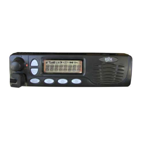
Page 4: Controls And Indicators
(4) CHANNEL SELECT/SPECIAL FUNCTION KEYS Used to select a channel and to adjust various parameters while in the Dealer program Mode. (5) LCD Used to display channel and operation status. (6) PROGRAMMABLE FUNCTION BUTTONS (7) SPEAKER Page 3 RELM Communications... -
Page 5: Lcd Icons
Priority Channel Stop Scan Blinking During Scan Scan Right Dot Home Channel Stop Talk Around Enable 10 Key lock Key Lock Enable 11 8 Segment Various Mode Indication 12 14 Segment Display Displays frequency and channel label information Page 4 RELM Communications... -
Page 6: Field (Keypad) Programming
Using the unit’s keypad, soft keys, and control knobs, the unit can be placed into one of two different programming modes. It is important to note that only RELM authorized dealers with qualified technicians are allowed to operate the RM series radios in the programming mode and to change any programming content. - Page 7 When selected, it will toggle the TX Power TX Power PKYxTPOW between “High” and “Low”. The “x” used in the display column for Function number 1 – 4 refers to “A”, “B”, “C”, or “D” function key. Page 6 RELM Communications...
- Page 8 0 ~ 3, 1 incremental Volume steps SPVL SPVL Beep 0 ~ 3, 1 incremental Sets the beep volume level. The higher the Volume steps number, the higher the level. SPVL Back-up State Table 2.2 – Dealer Mode Global Settings Page 7 RELM Communications...
- Page 9 T 1XXxxxx Frequency – 148 MHz use the [▲] or [▼] key to change the frequency. When the least significant digits are flashing, the increment change is determined by what is set in “TX Channel Steps”. Page 8 RELM Communications...
- Page 10 Table 2.3 – Dealer Mode Channel Settings CTCSS Tone Frequencies The CTCSS Tone Frequencies shown in table 2.4 are all possible CTCSS frequencies that can be programmed into the RM Series radios. The CTCSS frequencies listed that are shaded are standard TIA/EIA-603-A frequencies. Frequency...
-
Page 11: Programming By Computer
DCS Codes The CDCSS Codes shown in table 2.8 are all possible CDCSS Codes that can be programmed into the RM Series radios. The CDCSS Codes listed from 023 to 371 that are shaded are standard TIA/EIA-603-A frequencies. Table 2.5 – CDCSS Codes 2.1.2 Programming by Computer... - Page 12 RELM Wireless Corporation 7100 Technology Drive West Melbourne, FL 32904 (800) 422-6281 (321) 953-7986 service@RELM.com...
Need help?
Do you have a question about the RM Series and is the answer not in the manual?
Questions and answers