Table of Contents
Advertisement
Quick Links
THANK YOU!
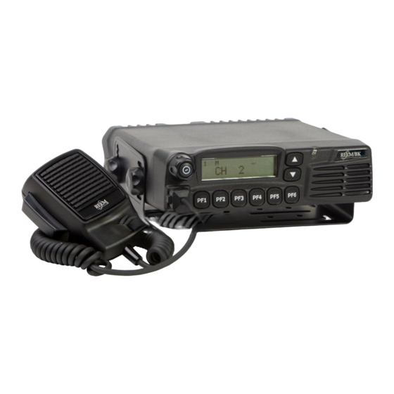
Thank you for your purchase of RELM mobile radio RM-800. We believe this
easy-to-use
radio
will
provide
you
with
dependable
and
reliable
communications at peak efficiency. Please read this manual carefully before
use. The information presented herein will help you to derive maximum
performance from your radio.
MODELS COVERED IN THIS MANUAL
RMV800 Mobile Radio
RMU800A Mobile Radio
American Communication Systems
Discover the Power of Communications
™
http://www.ameradio.com
TO ORDER – VISIT
1
Advertisement
Table of Contents

Related Manuals for RELM RM-800


Summary of Contents for RELM RM-800
- Page 1 THANK YOU! Thank you for your purchase of RELM mobile radio RM-800. We believe this easy-to-use radio will provide with dependable reliable communications at peak efficiency. Please read this manual carefully before use. The information presented herein will help you to derive maximum performance from your radio.
- Page 2 HOT SURFACE Avoid contact durin g prolonged use Do not touch the metal surface of the radio while it is in use. Do not mount the radio such that the chassis can come in contact with skin. High temperatures may burn you skin. ANDATORY AFETY NSTRUCTIONS TO...
- Page 3 by the manufacturer or radio dealer. You may be exposing person(s) to excessive radio frequency radiation. You may contact your radio dealer or the manufacturer for further instructions. Warning Maintain a separation distance from the antenna to person(s) at least 82cm (32inches). “This transmitter is authorized to operate with a maximum duty factor of 50%, in a typical push-to-talk mode, for satisfying FCC RF exposure compliance requirements.”...
-
Page 4: Table Of Contents
Contents Caution ANDATORY FETY NSTRUCTIONS User Safety, Training, and General Information Compliance with RF Energy Exposure Standards FCC Compliance Precautions Product Inspection Radio Installation and Warnings Radio Overview Basic Operations Turn the Radio On/Off Adjust the Volume Monitor Select a Channel Select a Zone Receive Transmit... - Page 5 Display Frequency Display Label Display Mode LCD Backlight Compander Scrambler Short Message GPS Report Optional Signalling User Set Mode Appendix 1 Entering Characters Optional Accessories...
-
Page 6: User Safety, Training, And General Information
BEFORE USING YOUR RELM MOBILE RADIO. n Compliance with RF Energy Exposure Standards Your RELM mobile radio is designed and tested to comply with a number of national and international standards and guidelines (listed below) regarding human exposure to radio frequency electromagnetic energy. -
Page 7: Fcc Compliance
Approved Accessories For a list of RELM approved accessories, see the accessories page of this user manual or visit the following website which lists approved accessories: http://www.RELM.com. n FCC Compliance Part 15 Compliance This equipment has been tested and found to comply with the limits for a Class B digital device, pursuant to part 15 of the FCC Rules. - Page 8 * Switch OFF the radio while refueling or parking at gas station. * Turn off your radio in any place where posted notices instruct you to do so. * Do not modify the radio for any reason. * Do not expose the radio to direct sunlight over a long time, nor place it close to heating source.
-
Page 9: Product Inspection
Product Inspection Please carefully unpack the radio. Before use, it is recommended that you inspect the product as follows. First check the shipping carton for any signs of damage. Confirm the supplied product against the packing slip to assure accuracy. If any items are missing or have been damaged during shipment, please file a claim to the carrier immediately. - Page 10 Radio Installation ¦ Installing the Radio 1. Attach the mounting bracket, using the 4.8 x 20mm self-tapping screws, in a location where convenient operation is accessible. 2. Connect the antenna and the supplied power cable to the radio. 3. Slide the radio into the mounting bracket and secure it using the Adjustment screws. 4.
- Page 11 ¦ Installation Tools The following tools are required for proper installation of your radio: Electric drill: ¢6mm or above Cross head Screwdriver Cross head screwdriver (used to fix 4.8 × 20mm self-tapping screw) ¦ Warnings 1. The radio operates in V negative ground systems only.
-
Page 12: Radio Overview
Radio Overview ¦ Front Panel View ? Power Switch Press to switch the radio on/off. ? Selector Knob Volume Up/Down, Channel Up/Down, Zone Up/Down features can be programmed to this knob (set by your dealer). Turn the knob clockwise to adjust upwards and counterclockwise to adjust downwards. ? LCD Display Please refer to “LCD Display”... - Page 13 ¦ LCD Display Indicator Description Display zone / channel number. Display zone / channel label (set by your dealer, up to 12 alphanumeric characters). Display channel Frequency Display the preprogrammed functions 1. Display zone / channel number. 2. Display transmit power level (H, M or L). 3.
- Page 14 Programmable Function Key PF1-PF6 key can be programmed with the following auxiliary functions: 1. Off 2. VOL UP 3. VOL Down 4. CH Up 5. CH Down 6. Zone Up 7. Zone Down 8. MoniA 9. MoniB 10. MoniC 11. MoniD 12.
- Page 15 Antenna Connector Used to connect external antenna. Power inlet Connector Adopt RELM-authorized DC power cable and 13.6 V input AC power. Speaker Jack Used to connect external speaker and only available for the plug of 3.5 mm. GPS Antenna Jack...
-
Page 16: Basic Operations
Basic Operations Turn the Radio On/Off Press the Power switch to switch the radio on. Press and hold the Power switch for approximately 1 second to switch the radio off. If Power on Password is set to protect your radio, “Chk P” and the cursor will appear on the display when power is turned on. -
Page 17: Select A Channel
Select a Channel Selector Knob, [? ] / [? ] or the function keys PF1-PF6 can be programmed with CH Up/ CH Down features to select a channel. Transmit/Receive frequencies of the channel are set by your dealer. Rotate the Selector Knob clockwise or press the key which be programmed as [CH Up] key to select a channel upwards;... -
Page 18: Beginning / End Of Transmission Id
Notes: ? Press the [TX Power] key while using a channel programmed with low power, an error tone will sound and the transmit power will not change. ? When changing a channel from high/middle power to low power, all other channels programmed with high/middle power will change to low power accordingly. - Page 19 ? Scan Restart When the radio stops on a busy channel, scanning can be restarted according to the restart mode, which can be programmed by the dealer as carrier-operated scan or time-operated scan. ? Carrier Operated Scan Scanning remains on an active channel until there are no activities; while the channel is free, the radio remains on the channel for the programmed Dropout Delay Time (programmed by your dealer) before it resumes scanning.
-
Page 20: Busy Channel Lockout (Bcl)
? Nuisance Channel Temporary Delete This feature allows you to temporarily delete a channel to/from the scan list during scanning. When scanning stops on an undesired channel (e.g. nuisance channel), press the key programmed as [Add/Del], the channel is temporarily removed from the scan list and scanning resumes. - Page 21 If this feature is activated, enter a preset DTMF number (16 digits maximum) in receive mode, then press the [PTT] key to place the call. The DTMF number scrolls across the LCD display as it is entered, and its corresponding audible tone sounds. Notes: ? If you enter a wrong digit or decide not to dial the number, press any key other than the power switch on the front panel to exit.
-
Page 22: Code Squelch
To cancel the process, press any key other than [0]~ [9]. 4. Press the [#] key, the stored DTMF number is cleared. ? Redial 1. Press the [*] key, “A--” appears on the LCD. 2. Press the [0] key twice, the last number (16 digits maximum) you dialed is redialed. The redialed number is displayed on the LCD. -
Page 23: Time-Out-Timer (Tot)
Squelch function. When activated, the radio will send a transpond signal when receiving the matching code. Four types of transpond signal can be programmed by your dealer: • Ringing tone • Alert Tone • Transpond code • Alert Tone + Transpond code Press any key to stop the ringing tone. - Page 24 for a preset time in turn automatically. While in Emergency mode, switch the power OFF or hold down the key again for longer than a preset time ("Emergency Key Delay Time", programmable by your dealer) to exit Emergency mode . Stun &...
-
Page 25: Programmable Auxiliary Functions
Programmable Auxiliary Functions Your dealer can program the following auxiliary functions to the programmable keys PF1-PF6. Reverse Frequency If communications between radios are disrupted because of a long distance from the repeater, reverse frequency function can be used to re-establish communications to another radio. -
Page 26: Public Address
1. Select your desired channel. 2. Press the key programmed as [UST] to enter the UST mode. 3. Use the Selector Knob to select a desired UST code/ name. The selected CTCSS/DCS frequency is valid only in UST mode. 4. Press the [UST] key again, the radio exits from UST mode and the LCD returns to the original display mode. -
Page 27: Selectable 2-Tone Encode
Selectable Two-Tone Encode 1. Press the key programmed as [TTS], the programmed 2-Tone code or name will be displayed on the LCD. 2. Turn the selector knob to select 2-Tone code (01-32) or name. 3. Hold down the [PTT] key to transmit the selected code. 4. - Page 28 Scrambler Press the key programmed as [Scrambler] to toggle Scrambler on/off. Note: Emphasis/de-emphasis features are turned off when scrambler is activated and turned on when scrambler is deactivated. GPS Report When GPS receiver is installed, press the key programmed as [Send GPS] to transmit your position data.
- Page 29 3 U RW HFW 0 RG H 0 HVVDJH. H\ 7U DQVIHU 0 VJ 9 L HZ 0 HVVDJH 5 HFHL YH0 VJ 6 HO HFW 0 VJ ' HO HW H0 VJ 7U DQVIHU 0 VJ 0 HVVDJH6 HQ W 6 HO HFW 0 VJ ' HO HW H0 VJ...
- Page 30 6) Select sending type, “Individual” or “Group Call”. 7) Use the knob selection/keypad entering to determine the desired receiver ID (individual/group). (Please refer to Appendix 1 for character input methods); or press PF6 to enter ID menu. 8) Press PF6 or the PTT key to send message. 2.
- Page 31 5) Select the content of the desired message; 6) Select “Protect Mode”, “Transfer Msg” or “Delete Msg”(Note 2); If “Delete Msg” is selected, the selected massage will be deleted. If “Transfer Msg” is selected, the following steps are required. 7) Select sending type, “Individual” or “Group Call”; 8) Use the knob selection/keypad entering to determine the desired receiver ID (individual/group).
- Page 32 Unmutes only when both CTCSS/DCS Activated only when both Optional Signalling CTCSS/DCS and Optional Signalling (2-Tone/5-Tone/DTMF/HDC2400 ) are (2-Tone/5-Tone/DTMF/ HDC2400 received and matches the preset one are received and matches the preset on selected channel. one on selected channel. Unmutes when either CTCSS/DCS or Activated only when...
- Page 33 Home Off Home Off Home Channel Home 1 On Home 1 On Home 2 On Home 2 On Home Both On Home Both On Zone Home Channel Home Zone Home Channel 1 Zone Selector Knob: change zone or channel Channel Home1 [PF5]: Toggle between zone and channel Home Channel 2...
- Page 34 CTCSS [PF4]: Toggle between (EIA standard mode) CTCSS 67.0 standard mode and step mode 67.0-254.1Hz [PF3]: Toggle between CDCSS CTCSS 254.1 and reverse CDCSS CTCSS (step: 0.1Hz) CTCSS 67.0* 67.0-254.1Hz CTCSS 254.1* CDCSS (standard mode) CDCSS 023N 023-754 CDCSS 754N CDCSS (1 step mode) CDCSS 000N*...
- Page 35 023-754 Reverse CDCSS 754 I CDCSS (1 step mode) CDCSS 000 I* 000-777 Reverse CDCSS 777 I* Hook & Moni Select submenu “Hook & Moni”, press [PF6] to enter Hook & Moni Mode. Function Setting Display Remarks Selected when hand Hook HandMic Hook microphone is used...
- Page 36 Scan PF1 Scan Scan Add/Del as not at scan status Add/Del PF1 Add/Del Temporarily delete nuisance channel Temporarily delete priority channel Reverse PF1 Reverse Reverse frequency Talk Around PF1 TA Talk around SEL SQL PF1 SELSQL Select squelch level Home CH PF1 HomeCH Home channel Public Address...
- Page 37 Add/Del PF2 Add/Del Temporarily delete nuisance channel Temporarily delete priority channel Reverse PF2 Reverse Reverse frequency Talk Around PF2 TA Talk around SEL SQL PF2 SELSQL Select squelch level Home CH PF2 HomeCH Home channel Public Address PF2 PA Public address Horn Alert PF2 HornAler Horn alert...
- Page 38 Talk Around PF3 TA Talk around SEL SQL PF3 SELSQL Select squelch level Home CH PF3 HomeCH Home channel Public Address PF3 PA Public address Horn Alert PF3 HornAler Horn alert LCD Backlight PF3 LCDBL LCD backlight Scrambler PF3 Scramble Scrambler Compander PF3 Compand...
- Page 39 Public Address PF4 PA Public address Horn Alert PF4 HornAler Horn alert LCD Backlight PF4 LCDBL LCD backlight Scrambler PF4 Scramble Scrambler Compander PF4 Compand Compander AUX A PF4 AUX A AUXA Port output control AUX B PF4 AUX B AUXB Port output control Send GPS PF4 SendGPS...
- Page 40 Scrambler PF5 Scramble Scrambler Compander PF5 Compand Compander AUX A PF5 AUX A AUXA Port output control AUX B PF5 AUX B AUXB Port output control Send GPS PF5 SendGPS Send GPS Emergency Call PF5 Emergency Emergency call Message PF5 Message Message [PF6] PF6 Off...
- Page 41 AUX B PF6 AUX B AUXB Port output control Send GPS PF6 SendGPS Send GPS Emergency Call PF6 Emergency Emergency call Message PF6 Message Message [Selector Knob] Volume Knob Volume Knob Volume Knob [Default] Channel Knob Channel Knob Channel selector knob Zone Knob Zone Knob Zone selector knob...
- Page 42 & < > “ ‘ Press to toggle between number and character Press to clear the input Enter (Complete programming and store) ? Entering characters without a keypad Turn Selector Knob to choose the character to be entered. Press the [PF2] key to toggle among number, uppercase letter, lowercase letter and symbol.
- Page 43 RELM endeavors to achieve the accuracy and completeness of this manual, but cannot guarantee its accuracy at all time. All the above specifications and design are subject to change by RELM without notice. All the reproduction and translation of this manual without authorization of RELM is not allowed.
Need help?
Do you have a question about the RM-800 and is the answer not in the manual?
Questions and answers