Table of Contents
Advertisement
Advertisement
Table of Contents

Related Manuals for Mitsubishi Electric PEA-RP200WKA


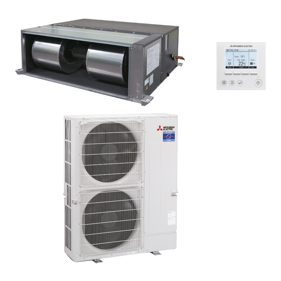
Summary of Contents for Mitsubishi Electric PEA-RP200WKA
- Page 3 CONTENTS...
-
Page 4: Safety Precaution
SAFETY PRECAUTION 1-1. ALWAYS OBSERVE FOR SAFETY Before obtaining access to terminal, all supply circuits must be disconnected. 1-2. CAUTIONS RELATED TO NEW REFRIGERANT Cautions for units utilising refrigerant R410A Use new refrigerant pipes. Do not use refrigerant other than R410A. In case of using the existing pipes for R22, be careful with If other refrigerant (R22 etc.) is used, chlorine in refrige- the followings. -
Page 5: Part Names And Functions
Unit Gravimeter [3] Service tools Use the below service tools as exclusive tools for R410A refrigerant. Tool name Specifications Gauge manifold · Only for R410A · Use the existing fitting specifications. (UNF1/2) · Use high-tension side pressure of 5.3MPa·G or over. Charge hose ·... - Page 6 • Wired remote controller (Option) PAR-33MAA The functions which can be used are restricted according to each model. The main display can be displayed in 2 different modes: "Full" and "Basic." Display The initial setting is "Full." 1 Operation mode Indoor unit operation mode appears here.
-
Page 7: Menu Structure
Menu structure Press the button. MENU Main menu Move the cursor to the desired item with the buttons, and press the button. SELECT Vane Louver Vent. (Lossnay) • • High power Timer ON/OFF timer Auto-OFF timer Weekly timer Restriction Temp. range Operation lock Energy saving Auto return... -
Page 8: Setting Details
Setting and display items Setting details Vane Louver Vent. Use to set the vane angle. • • • Select a desired vane setting from 5 different settings. (Lossnay) Use to turn ON/OFF the louver. • Select a desired setting from "ON" and "OFF." Use to set the amount of ventilation. -
Page 9: Specification
SPECIFICATION Model name PEA-RP200WKA Mode Cooling Heating Power supply Single phase, 50Hz, 220-240V ❇ Input 0.66 ❇ Running Current 3.57 External finish Galvanized sheets Heat exchanger Plate fin coil Fan (drive) × No. Sirocco fan × 2 Fan motor output 0.87... -
Page 10: Fan Performance And Corrected Air Flow
FAN PERFORMANCE AND CORRECTED AIR FLOW PEA-RP200WKA (External static pressure 60 Pa) (External static pressure 75 Pa) High High Middle Rated point Middle Rated point Airflow rate (m /min) Airflow rate (m /min) (External static pressure 100 Pa) (External static pressure 150 Pa) - Page 11 PEA-RP250WKA (External static pressure 60Pa) (External static pressure 75Pa) [0.803] [0.803] [0.602] [0.602] Limit Limit Limit High [0.401] [0.401] High Rated point Rated point Middle Rated point Rated point Middle [0.201] [0.201] [1766] [1942] [2119] [2295] [2472] [2648] [2825] [3001] [3178] [1766] [1942]...
-
Page 12: Sound Pressure Level
SOUND PRESSURE LEVELS 5-1. Sound pressure level Ceiling concealed Outlet Inlet easurement point 5-2. NC curves PEA-RP200WKA (External static pressure 60 Pa) (External static pressure 75 Pa) 70.0 70.0 High High 65.0 Middle 65.0 Middle 60.0 60.0 NC-60 NC-60 55.0 55.0... - Page 13 PEA-RP250WKA (External static pressure 60Pa) (External static pressure 75Pa) (External static pressure 100Pa) (External static pressure 150Pa) NOTE: The sound level is measured in an anechoic room where echoes are few, when compressor stops. The sound may be bigger than displayed level under actual installation condition by surrounding echoes. The sound level can be higher than the displayed level during cooling and heating operation.
-
Page 14: Outlines And Dimensions
OUTLINES & DIMENSIONS INDOOR UNIT... -
Page 15: Wiring Diagram
WIRING DIAGRAM... -
Page 16: Refrigerant System Diagram
REFRIGERANT SYSTEM DIAGRAM Heat exchanger Refrigerant GAS pipe connection (Brazed (PEA-200,250)) Thermistor TH5 (Cond./ Eva.temperature) Refrigerant flow in cooling Refrigerant flow in heating Refrigerant LIQUID pipe connection (Brazed (PEA-200,250)) Thermistor TH2 Pipe temperature(Liquid) Thermistor TH1 (Room temperature) Distributor with strainer (#100) -
Page 17: Troubleshooting
TROUBLESHOOTING 9-1. CAUTIONS ON TROUBLESHOOTING (1) Before troubleshooting, check the followings: 1 Check the power supply voltage. 2 Check the indoor/outdoor connecting wire for mis-wiring. (2) Take care the followings during servicing. 1 Before servicing the air conditioner, be sure to turn off the remote controller first to stop the main unit, and then turn off the breaker. -
Page 18: Wireless Remote Controller
• If the unit cannot be operated properly after the test run has been performed, refer to the following table to remove the cause. Symptom Cause Wired remote controller LED 1, 2 (PCB in outdoor unit) For about 2 •For about 2 minutes after power-on,op- After LED 1, 2 are lighted, LED 2 is PLEASE WAIT minutes after... - Page 19 Digital error display on wireless remote controller When air conditioner detects an error, the operation lamp on the indoor unit infrared adaptor will blink to indicate that the unit has come to an abnormal stop. There are two error output patterns A and B as shown below. [Output pattern A] Confirmation of the connection to the wireless (ms)
- Page 20 • If the unit cannot be operated properly after the above test run has been performed, refer to the following table to remove the cause. Symptom Cause Wired remote controller LED 1, 2 (PCB in outdoor unit) • For about 2 minutes after power-on, operation of the After LED 1, 2 are lighted, LED 2 is turned For about 2 minutes PLEASE WAIT...
- Page 21 Note: Refer to the manual of outdoor unit for the details of display 9-3. SELF-DIAGNOSIS ACTION TABLE such as F, U, and other E. Abnormal point and detection method Countermeasure Error Code Cause Room temperature 1 Defective thermistor 1–3 Check resistance value of thermistor. thermistor (TH1) characteristics 0: ······15.0k"...
- Page 22 Abnormal point and detection method Countermeasure Error Code Cause Freezing/overheating protection is (Cooling or drying mode) (Cooling or drying mode) working 1 Clogged filter (reduced airflow) 1 Check clogging of the filter. 1 Freezing protection (Cooling mode) 2 Short cycle of air path 2 Remove shields.
- Page 23 Abnormal point and detection method Countermeasure Error Code Cause Abnormality of pipe temperature ther- 1 Defective thermistor 1–3 Check resistance value of thermistor. mistor/Condenser-Evaporator (TH5) For characteristics, refer to (P1) above. characteristics 2 Check contact failure of connector (CN44) 1 The unit is in three-minute resume pro- 2 Contact failure of connector on the indoor controller board.
- Page 24 Abnormal point and detection method Countermeasure Error Code Cause ∗ Check LED display on the outdoor control cir- Indoor/outdoor unit communication 1 Contact failure, short circuit or, error (Signal receiving error) cuit board. (Connect A-control service tool, mis-wiring (converse wiring) of 1 Abnormal if indoor controller board PAC-SK52ST.) indoor/outdoor unit connecting...
- Page 25 Abnormal point and detection method Countermeasure Error Code Cause Inverter-related problem is detected. 1) Power supply environment Find out if there was a (momentary) power failure. Check whether the power voltage is 198V or above across all phases. 2) Static pressure setting error Check that the static pressure setting and the design static pressure are correct.
- Page 26 9-4. TROUBLESHOOTING BY INFERIOR PHENOMENA Note: Refer to the manual of outdoor unit for the detail of remote controller. Phenomena Cause Countermeasure (1)LED2 on indoor controller board • When LED1 on indoor controller board is also off. is off. 1 Power supply of rated voltage is not supplied to out- 1 Check the voltage of outdoor power door unit.
-
Page 27: Test Point Diagram
9-5. TEST POINT DIAGRAM 9-5-1. NF board Power supply voltage (220 - 240VAC) CNDP CNACL Connect to the AC reactor CNR1 Connect to the Resistor CNDB Connect to the Diode bridge CNPW1 Connect to the power supply board CNFAN Connect to the INV board CNXB1 Connect to the indoor controller board Measure the charged voltage of the inverter... -
Page 28: Power Supply Board
9-5-2. Power supply board CNPW2 Connect to the NF board Connect to the indoor controller board CNCX1 Connect to the indoor controller board CNRSC CNRSP Connect to the INV board CN18V Connect to the INV board CNPW2 CN18V CNRSP CNXC1 CNRSC... - Page 29 9-5-3. Indoor controller board Emergency operation Model selection Capacity setting Remote start/stop adapter CN32 For MA remote controller cable connection CN22 (10 - 13 VDC (Between 1 and 3.)) Centralized control CN51 JAMA standard HA terminal A CN41 Thermistor CN44 (liquid/condenser/evaporator temperature) Float thermistor CN4F...
- Page 30 9-5-4. INV board Inverter function setting Connect to the NF board CNVDC Connect to the FAN motor (power line) CNINV Connect to the power supply board CN15V Connect to the power supply board CNRS2 Connect to the FAN motor (rotor position sensor input) CNCT1 Connect to the current sensor CNCT2...
-
Page 31: Trouble Criterion Of Main Parts
9-6. TROUBLE CRITERION OF MAIN PARTS Part name Check method and criterion Room temperature Measure the resistance with a tester. thermistor (Part temperature 10°C ~ 30°C) (TH1) Normal Abnormal Pipe temperature 4.3kΩ~9.6kΩ Opened or short-circuited thermistor/liquid (TH2) Condenser/evaporator temperature thermistor (TH5) 9-7. - Page 32 9-8. DC FAN MOTOR (FAN MOTOR / INV BOARD) If the static pressure settings for the unit and the duct do not match, the fan motor may repeat start/stop. a. If there are problems only with the fan motor, replace the fan motor only. (Fan motor failure will cause an overcurrent to pass through the inverter, but the inverter is protected from damage with the protection function that will stop the inverter when an overcurrent is detected.) b.
- Page 33 (2) Troubleshooting the inverter output-related problems Check items Symptoms Actions to take 1 Overcurrent errors 1 Turn off the breaker. Replace the INV board. Check the INV board *Be sure to turn off the error detection circuit. breaker. 2 Logic error Replace the INV board.
- Page 34 (3) Troubleshooting when the main power breaker trips Check items Symptoms Actions to take Check the resistance between the terminals 1 0 to several ohms, or insulation Check the components in the main inverter circuit. of power supply terminal block TB2 with an resistance failure ohmmeter.
- Page 35 (4) Simple check on the main inverter circuit components * Turn off the power supply, take the following components out of the control box, and then check the components. Parts name Evaluation criteria Diode bridge Refer to (5) Troubleshooting the diode bridge. Measure the resistance between terminals.
- Page 36 (6) Precautions for inverter parts replacement 1 Check for faulty or loose wiring. To avoid damage to the IPM, thoroughly check the wiring to the main circuit components in the diode bridge. 2 Coat the radiation surface of the IPM and diode bridge evenly with the grease that is provided with the service parts.
- Page 37 9-9. FUNCTIONS OF DIP SWITCH AND JUMPER WIRE Each function is controlled by the dip switch and the jumper wire on control p.c. board. SW1 and SW2 are equipped only for service parts. Model setting and capacity setting are memorized in the nonvolatile memory of the control p.c. board of the unit.
-
Page 38: Disassembly Procedure
DISASSEMBLY PROCEDURE Exercise caution when removing heavy parts. 1. Control box 1. Removing the control box cover (1) Remove the two fixing screws on the cover (A) to remove it. Fig. 1 Fig. 2 2. Thermistor (Intake air) 1. Remove the control box cover according to the procedure in section 1. - Page 39 Exercise caution when removing heavy parts. 3. Thermistor (Condenser/evaporator) (Liquid pipe) 1. Remove the control box cover according to the procedure in section 1. 2. Removing the maintenance cover (1) Remove the ten fixing screws on the cover (D), cover (E), and cover (F) to remove the maintenance cover.
-
Page 40: Drain Pan
Exercise caution when removing heavy parts. 4. Drain pan 1. Removing the bottom plate (1) Remove the twelve fixing screws on the bottom plate (J) to remove it. Fig. 6 2. Removing the drain pan (1) Pull out the drain pan (K) in the direction of the arrow. -
Page 41: Heat Exchanger
Exercise caution when removing heavy parts. 5. Heat exchanger 1. Remove the control box cover according to the procedure in section 1. 2. Remove the maintenance cover according to the procedure in section 3. 2. 3. Disconnect the thermistor connector according to the procedure in section 3. - Page 42 Exercise caution when removing heavy parts. 6. Reactor, fan, and fan motor (top side maintenance) 1. Remove the control box cover according to the procedure in section 1. 2. Removing the fan motor and ACL cable (1) Disconnect the connector (CNCT1) from the INV board and connector (CNACL) from the noise filter board.
- Page 43 Exercise caution when removing heavy parts. 7. Reactor, fan, and fan motor (bottom side maintenance) 1. Remove the control box cover according to the Noise filter board procedure in section 1. INV board 2. Removing the fan motor and ACL cable (1) Disconnect the connector (CNCT1) from the INV board and connector (CNACL) from the noise fil- ter board.
- Page 44 Exercise caution when removing heavy parts. 8. Separating the unit 1. Removing the covers (1) Remove the two fixing screws on the control box cover to remove it. (2) Remove the three fixing screws on the lead wire cover to remove it. Lead wire cover Control box...
- Page 45 FUNCTION SETTINGS (Function selection via the remote controller) Function setting on the unit (Selecting the unit functions) [Fig. 11.1] [Fig. 11.2] [Fig. 11.3] Service menu Function setting Function setting Grp. Test run Ref. address Ref. address Mode 1 Input maintenance info. Unit No.
- Page 46 Function table 1 Select unit number 00 Mode Settings Mode no. Setting no. Initial setting Check Not available Power failure automatic recovery (AUTO RESTART FUNCTION) Available Indoor unit operating average Indoor temperature detecting Set by indoor unit’s remote controller Remote controller’s internal sensor Not Supported LOSSNAY connectivity Supported (indoor unit is not equipped with outdoor-air intake)
-
Page 47: Optional Parts
OPTIONAL PARTS Drain pump PAC-KE05DM-F...
Need help?
Do you have a question about the PEA-RP200WKA and is the answer not in the manual?
Questions and answers