Table of Contents
Advertisement
Quick Links
Advertisement
Table of Contents

Summary of Contents for Danaher SERVOSTAR 300 Series
- Page 1 Artisan Technology Group is your source for quality new and certified-used/pre-owned equipment SERVICE CENTER REPAIRS WE BUY USED EQUIPMENT • FAST SHIPPING AND DELIVERY Experienced engineers and technicians on staff Sell your excess, underutilized, and idle used equipment at our full-service, in-house repair center We also offer credit for buy-backs and trade-ins •...
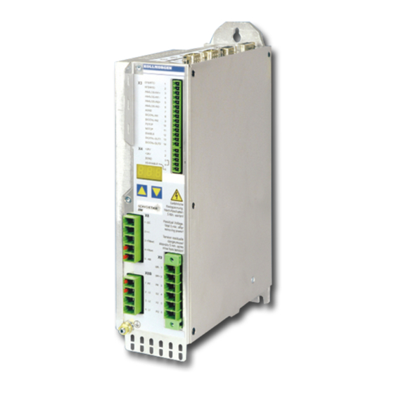
- Page 2 ® SERVOSTAR Digital Servo Amplifier Product Manual Edition 10/2007 Valid for Hardware Revision 02.01 Keep all manuals as a product component during the life span of the product. Pass all manuals to future users / owners of the product. File sr300_e.***...
- Page 3 HIPERFACE is a registered trademark of Max Stegmann GmbH EnDat is a registered trademark of Dr. Johannes Heidenhain GmbH SERVOSTAR is a registered trademark of Danaher Motion Technical changes which improve the performance of the equipment may be made without prior notice! Printed in the Federal Republic of Germany All rights reserved.
-
Page 4: Table Of Contents
Danaher Motion Contents 10/2007 page General About this manual ..............7 Target group . - Page 5 Contents Danaher Motion 10/2007 page Electrical installation Important notes..............39 Guide to electrical installation.
- Page 6 Danaher Motion Contents 10/2007 page Setup Important notes..............83 Setup software .
- Page 7 Contents Danaher Motion 10/2007 page 10.5 Expansion card -DEVICENET-........... .108 10.5.1...
-
Page 8: General
Danaher Motion General 10/2007 General About this manual ® This manual describes the SERVOSTAR 300 series of digital servo amplifiers (standard version: 1.5A ...10A rated current). A more detailed description of the expansion cards that are currently available and the... -
Page 9: Abbreviations Used
General Danaher Motion 10/2007 Abbreviations used Abbrev. Meaning AGND Analog ground Restart lock BTB/RTO Ready to operate Fieldbus (CANopen) Communité Europeenne Clock signal Serial interface for a PC-AT DGND Digital ground (for 24V and digital I/O) German Institute for Industrial Standards... -
Page 10: Safety Instructions
Danaher Motion Safety 10/2007 Safety Safety Instructions Only properly qualified personnel are permitted to carry out activities such as transport, installation, commissioning and maintenance. Properly qualified per- sons are those who are familiar with the transport, assembly, installation, com- missioning and operation of the product, and who have the appropriate qualifi- cations for their job. -
Page 11: Use As Directed
Servo amplifiers in the SERVOSTAR 300 series can be supplied from 3-phase grounded (earthed) industrial supply networks (TN-system, TT-system with grounded... -
Page 12: Standards
Danaher Motion Standards 10/2007 Standards Approvals of the servo amplifiers 3.1.1 CE conformance Conformance with the EC EMC Directive 2004/108/EC and the Low Voltage Directive 2006/95/EC is mandatory for the supply of servo amplifiers within the European Commu- nity. Product standard EN 61800-3 is applied to ensure conformance with the EMC Direc- tive. -
Page 13: European Directives And Standards For The Machine Builder
Standards Danaher Motion 10/2007 European Directives and Standards for the machine builder Servo amplifiers are components that are intended to be incorporated into electrical plant and machines for industrial use. When the servo amplifiers are built into machines or plant, the amplifier must not be used until it has been established that the machine or... -
Page 14: Handling
Disposal In accordance to the WEEE-2002/96/EG-Guidelines we take old devices and accessories back for professional disposal, if the transport costs are taken over by the sender. Send the devices to: Danaher Motion GmbH Wacholderstr. 40-42 D-40489 Düsseldorf, Germany ® SERVOSTAR... -
Page 15: Package Supplied
Package Danaher Motion 10/2007 Package Package supplied When you order an amplifier from the SERVOSTAR 300 series (order numbers ð p.119), you will receive: — SERVOSTAR 3xx — Mating connectors X0, X3, X4, X8 — Mating connector X9 only with SERVOSTAR 303-310 (S3xx6) —... -
Page 16: Part Number Scheme
Danaher Motion Package 10/2007 Part number scheme S 3 0 6 0 1 - S E* Expansions Family no expansion S300 DEVICENET PROFIBUS SERCOS Current rating ETHERCAT 1.5A rms SYNQNET 3A rms I/O Extension 6A rms 10A rms Electr. options... -
Page 17: Technical Description
Technical description Danaher Motion 10/2007 Technical description The SERVOSTAR 300 family of digital servo amplifiers Standard version Two voltage classes with large nominal voltage range +10% 1 x 110V ... 3 x 230V (SERVOSTAR 303-310, S3xx6) -10% + 10% 3 x 208V ... - Page 18 Danaher Motion Technical description 10/2007 Auxiliary supply voltage 24V DC Electrically isolated, internal fusing, from an external 24V DC power supply unit with, for instance, isolating transformer or uninterruptible power supply. Operation and parameter setting With our user-friendly setup software, for setup via the serial interface of a PC.
-
Page 19: Technical Data
Technical description Danaher Motion 10/2007 Technical data 6.2.1 Technical data for 110/230 V (types S3_ _6_) SERVOSTAR Electrical data Order Code — S30361 S30661 S31061 +10% 1 x 110V … 1 x 230V -10% Rated supply voltage +10% 3 x 110V …... -
Page 20: Technical Data For 400/480 V (Types S3
Danaher Motion Technical description 10/2007 6.2.2 Technical data for 400/480 V (types S3_ _0_) SERVOSTAR Electrical data Order Code — S30101 S30301 S30601 +10% Rated supply voltage 3 x 208V … 480V , 50/60 -10% (grounded supply, phase to phase) Rated input power for S1 operation Max. -
Page 21: Inputs / Outputs
Technical description Danaher Motion 10/2007 6.2.3 Inputs / outputs ±10 Analog inputs 1, 2 (resolution 14/12 bit) ±10 Max. common-mode voltage Digital control inputs V as per EN 61131-2 Type 1, max. 30VDC Digital control outputs, active high open Emitter, max. 30VDC, 10mA DC max. -
Page 22: Ambient Conditions, Ventilation, Mounting Position
For multi-axis systems, observe the specific operating conditions for your system. To reach the max. permitted cable length, observe cable requirements ð p. 43. * Danaher Motion North America supplies cables up to 39 meters Danaher Motion Europe supplies cables up to max. length ®... -
Page 23: Motor Holding Brake
Technical description Danaher Motion 10/2007 Motor holding brake A 24V / max.1.5A holding brake in the motor can be controlled directly by the amplifier. Check voltage drop, measure the voltage at brake input and check brake function (brake and no brake). This function does not ensure personnel safety! The brake function must be enabled through the BRAKE setting (screen page: Motor). -
Page 24: Led Display
Danaher Motion Technical description 10/2007 LED display A 3-character LED display indicates the status of the amplifier after switching on the 24V supply (ð p.97). When the keys on the front panel are used, the parameter and function numbers are shown, as well as the numbers for any errors that may occur (ð p.98). - Page 25 Technical description Danaher Motion 10/2007 Technical Data: Regen circuit Supply voltage / V Rated data Dim. Switch-on (upper) threshold of regen circuit Overvoltage F02 Regen resistor (internal) Continuous power in regen circuit (RBint) — Pulse power in regen circuit (RBint max. 1s) 0.75...
-
Page 26: Switch-On And Switch-Off Behavior
Danaher Motion Technical description 10/2007 Switch-on and switch-off behavior This chapter describes the switch-on and switch-off behavior of the SERVOSTAR and the steps required to achieve operational stopping or emergency stop behavior that complies with standards. The servo amplifier’s 24 V supply must remain constant. The ASCII commands ACTFAULT (error response) and STOPMODE (ENABLE signal response) dictate how the drive will behave. -
Page 27: Behavior In Standard Operation
Technical description Danaher Motion 10/2007 6.7.1 Behavior in standard operation The behavior of the servo amplifier always depends on the current setting of a number of different parameters (e.g., ACTFAULT, VBUSMIN, VELO, STOPMODE, etc.; see online help). The diagram below illustrates the correct functional sequence for switching the servo amplifier on and off. -
Page 28: Behavior In The Event Of An Error (With Standard Setting)
Danaher Motion Technical description 10/2007 6.7.2 Behavior in the event of an error (with standard setting) The behavior of the servo amplifier always depends on the current setting of a number of different parameters (e.g., ACTFAULT, VBUSMIN, VELO, STOPMODE, etc.; see online help). -
Page 29: Stop- / Emergency Stop- Function To En 60204
Technical description Danaher Motion 10/2007 Stop- / Emergency Stop- Function to EN 60204 With the personnel safe, TÜV-approved restart lock –AS- (see page 77 onwards) the drive can be secured on standstill (torque-free) using its internal electronics so that even when power is being supplied, the drive shaft is protected against unintentional restart (Category 3, in accordance with EN954-1). -
Page 30: Emergency Stop: Standards
Danaher Motion Technical description 10/2007 6.8.2 Emergency Stop: Standards The emergency Stop function is used for the fastest possible shut-down of the machine in a dangerous situation. The Emergency Stop function can be triggered by the actions of a single person. It must be fully functional and available at all times. The user must not have to work out how to operate this mechanism. -
Page 31: Implementation Of The Stop Category 0
Technical description Danaher Motion 10/2007 6.8.3 Implementation of the Stop Category 0 Bringing the motor to a standstill by immediately switching off the amplifier power supply (STOPMODE & ACTFAULT parameters set to 1). The switching sequence is precisely determined by this circuit in order to avoid undesirable fault messages and servo ampli- fier failures. -
Page 32: Implementation Of The Stop Category 1
Danaher Motion Technical description 10/2007 6.8.4 Implementation of the Stop Category 1 Bringing the motor to a standstill by interrupting the mains supply and using controlled electronic braking (STOPMODE & ACTFAULT parameters set to 1). The 24 V supply for the SERVOSTAR must remain constant. -
Page 33: Implementation Of The Stop Category 2
Technical description Danaher Motion 10/2007 6.8.5 Implementation of the Stop Category 2 The machine receives an operational stop (disable) command and brakes the drive using the set braking ramp (STOPMODE & ACTFAULT parameters set to 1). The drive is braked in a controlled manner during the stopping (disabling) procedure. If the speed VEL0 (see sequence diagram in chapter 6.3) is undershot, the holding brake is... -
Page 34: Shock-Hazard Protection
Danaher Motion Technical description 10/2007 Shock-hazard protection 6.9.1 Leakage current Leakage current via the PE conductor results from the combination of equipment and cable leakage currents. The leakage current frequency pattern comprises a number of frequencies, whereby the residual-current circuit breakers definitively evaluate the 50Hz current. -
Page 35: Isolating Transformers
Technical description Danaher Motion 10/2007 6.9.3 Isolating transformers If protection against indirect contact is absolutely essential despite a higher leakage cur- rent, or if an alternative form of shock-hazard protection is sought, the SERVOSTAR 300 can also be operated via an isolating transformer (schematic connection see p.48). -
Page 36: Mechanical Installation
Danaher Motion Mechanical Installation 10/2007 Mechanical Installation Important notes Protect the servo amplifier from impermissible stresses. In particular, do not let any components become bent or any insulation distances altered during transport and handling. Avoid contact with electronic components and contacts. -
Page 37: Assembly
Mechanical Installation Danaher Motion 10/2007 Assembly Material: 3 x M5 hexagon socket screws to DIN 912 Tool required : 4 mm Allen key SERVOSTAR 300 ® SERVOSTAR 300 Product Manual... -
Page 38: Dimensions
Danaher Motion Mechanical Installation 10/2007 Dimensions ® SERVOSTAR 300 Product Manual... - Page 39 Mechanical Installation Danaher Motion 10/2007 This page has been deliberately left blank. ® SERVOSTAR 300 Product Manual...
-
Page 40: Electrical Installation
Danaher Motion Electrical installation 10/2007 Electrical installation Important notes Check the combination of servo amplifier and motor. Compare the rated voltage and current of the units. Implement the wiring according to the connection diagram on page 41. Make sure that the maximum permissible rated voltage at the terminals L1, L2, L3 or +DC, –DC is not exceeded by more than 10% even in the most unfavorable circums-... -
Page 41: Guide To Electrical Installation
Electrical installation Danaher Motion 10/2007 Guide to electrical installation The following notes should help you to carry out the electrical installation in a sensible sequence, without overlooking anything important. Cable selection Select cables in accordance with EN 60204 ð p.21. -
Page 42: Wiring
Danaher Motion Electrical installation 10/2007 Wiring 8.3.1 Important Notes Only professional staff who are qualified in electrical engineering are allowed to install the servo amplifier. The installation procedure is described as an example. A different procedure may be appropriate or necessary, depending on the application of the equipments. -
Page 43: Shielding Connection To The Front Panel
Electrical installation Danaher Motion 10/2007 8.3.2 Shielding connection to the front panel Remove the outside shroud of the cable and the shielding braid on the desired core length. Secure the cores with a cable tie. Remove the outside shroud of the line on a length from for instance 30mm without da- maging the shielding braid. -
Page 44: Technical Data For Connecting Cables
Danaher Motion Electrical installation 10/2007 8.3.3 Technical data for connecting cables Further information on the chemical, mechanical and electrical characteristics of the cables can be obtained from our customer service. Observe the rules in the section "Conductor cross-sections" on page 21. To reach the max. -
Page 45: Components Of A Servo System
Electrical installation Danaher Motion 10/2007 Components of a servo system Controls / PLC SERVOSTAR 300 24V PSU Fuses Regen resistor (optional) Drive cut-out Motor choke (optional) Terminals Motor Cables drawn bold are shielded. Electrical ground is drawn with dash-dotted lines. -
Page 46: Block Diagram
Danaher Motion Electrical installation 10/2007 Block diagram The block diagram below just provides an overview. ® SERVOSTAR 300 Product Manual... -
Page 47: Connector Assignments
Electrical installation Danaher Motion 10/2007 Connector assignments The connectors of the expansion card depend on used expansion card (see pages 102 ff). ® SERVOSTAR 300 Product Manual... -
Page 48: Connection Diagram (Overview)
Danaher Motion Electrical installation 10/2007 Connection diagram (Overview) Refer to the Safety Instructions (ð p.9) SERVOSTAR 300 and Use as Directed (ð p.10) ! ð p.54ff ð p.72 ð p.53 ð p.73 ð p.51 ð p.74 ð p.78 ð p.73 ð... -
Page 49: Electrical Supply
Electrical installation Danaher Motion 10/2007 Electrical supply 8.8.1 Connection to various mains supply networks This page illustrates all the possible connection variations for different electrical supply networks. An isolating transformer is always required for 400 … 480V networks that are asymmetrically grounded or not grounded. -
Page 50: Mains Supply Connection (X0)
Danaher Motion Electrical installation 10/2007 8.8.2 Mains supply connection (X0) 8.8.2.1 Three phase — Directly to 3-phase supply network, filter is integrated Fusing (e.g. fusible cut-outs) to be provided by the user ð p.20 — SERVOSTAR 300 8.8.2.2 Two phase without neutral SERVOSTAR 300 8.8.2.3... -
Page 51: Auxiliary Supply (X4)
Electrical installation Danaher Motion 10/2007 8.8.3 24V auxiliary supply (X4) — External 24V DC power supply, electrically isolated, e.g. via an isolating transformer — Required current rating ð p.18 — Integrated EMC filter for the 24V auxiliary supply SERVOSTAR 300 8.8.4... -
Page 52: Motor Connection With Brake (X9)
Danaher Motion Electrical installation 10/2007 Motor connection with brake (X9) Cable length £ 25 meters SERVOSTAR 300 Cable length >25 meters For cable lengths above 25m up to max. 50m, the motor choke 3YL must be wired into the motor cable, close to the amplifier. -
Page 53: Feedback
The table below provides an overview of the supported feedback types, their correspond- ing parameters and a reference to the relevant connection diagram in each case. On each of these, the pin assignment shown on the encoder side relates to the Danaher Motion motors. -
Page 54: Resolver (X2)
Danaher Motion Electrical installation 10/2007 8.11.1 Resolver (X2) Connection of a Resolver (2 to 36-poles) as a feedback system (primary, ð p.52). The thermostat contact in the motor is connected via the resolver cable to X2 and evaluated there. If cable lengths of more than 100 meters are planned, please contact our customer ser- vice. -
Page 55: Sine Encoder With Biss (X1)
Electrical installation Danaher Motion 10/2007 8.11.2 Sine Encoder with BISS (X1) Wiring of a single-turn or multi-turn sine-cosine encoder with BISS interface as a feed- back system (primary, ð p.52). The thermostat contact in the motor is connected via the encoder cable to X1 and evaluated there. -
Page 56: Sine Encoder With Endat 2.1
Danaher Motion Electrical installation 10/2007 8.11.3 Sine Encoder with EnDat 2.1 Wiring of a single-turn or multi-turn sine-cosine encoder with EnDat interface as a feed- back system (primary and secondary, ð p.52). Preferred types are the ECN1313 and EQN1325 encoders. -
Page 57: Sine Encoder With Hiperface (X1)
Electrical installation Danaher Motion 10/2007 8.11.4 Sine Encoder with HIPERFACE (X1) Wiring of a single-turn or multi-turn sine-cosine encoder with HIPERFACE interface as a feedback system (primary and secondary, ð p.52). The thermostat contact in the motor is connected via the encoder cable to X1 and evalu- ated there. -
Page 58: Sine Encoder Without Data Channel (X1)
Danaher Motion Electrical installation 10/2007 8.11.5 Sine Encoder without data channel (X1) Wiring of a sine-cosine encoder without data channel as a feedback (primary and sec- ondary, ð p.52). Every time the 24V auxiliary voltage is switched on, the amplifier needs start-up information for the position controller (parameter value MPHASE). -
Page 59: Sine Encoder With Hall (X1)
Electrical installation Danaher Motion 10/2007 8.11.6 Sine Encoder with Hall (X1) Feedback devices (incremental or sine-cosine), which don't deliver an absolute informa- tion for commutation, can be used as complete feedback system combined with an addi- tional Hall encoder (primary, ð p.52). -
Page 60: Rod (Aquadb) 5V (X1)
Danaher Motion Electrical installation 10/2007 8.11.7 ROD (AquadB) 5V (X1) Wiring of a 5V incremental encoder (ROD, AquadB) as a feedback (primary, ð p.52). The thermostat contact in the motor is connected to X1 and evaluated there. Every time the 24V auxiliary voltage is switched on, the amplifier need start-up informa- tion for the position controller (parameter value MPHASE). -
Page 61: Rod (Aquadb) 5V With Hall (X1)
Electrical installation Danaher Motion 10/2007 8.11.8 ROD (AquadB) 5V with Hall (X1) Wiring of a ComCoder as a feedback unit (primary, ð p.52). For the commutation hall sensors are used and for the resolution an incremental encoder. The thermostat contact in the motor is connected to X1 and evaluated there. -
Page 62: Rod (Aquadb) 5V (X5)
Danaher Motion Electrical installation 10/2007 8.11.9 ROD (AquadB) 5V (X5) A 5V incremental encoder (AquadB) can be used as standard motor feedback (primary and secondary, ð p.52). The thermostat contact in the motor is connected to X1. Every time the 24V auxiliary voltage is switched on, the amplifier need start-up informa- tion for the position controller (parameter value MPHASE). -
Page 63: Rod (Aquadb) 5V With Hall (X5/X1)
Electrical installation Danaher Motion 10/2007 8.11.10 ROD (AquadB) 5V with Hall (X5/X1) Wiring of a 5V incremental encoder (ROD, AquadB) with Hall sensors as a feedback unit (primary, ð p.52). For the commutation hall sensors are used and for the resolution an incremental encoder. -
Page 64: Rod (Aquadb) 24V (X3)
Danaher Motion Electrical installation 10/2007 8.11.11 ROD (AquadB) 24V (X3) Wiring of a 24V incremental encoder (ROD AquadB) as a feedback system (primary or secondary, ð p.52). The thermostat contact in the motor is connected to X1 or X2. Every time the 24V auxiliary voltage is switched on, the amplifier need start-up informa- tion for the position controller (parameter value MPHASE). -
Page 65: Rod (Aquadb) 24V With Hall (X3/X1)
Electrical installation Danaher Motion 10/2007 8.11.12 ROD (AquadB) 24V with Hall (X3/X1) Wiring of a 24V incremental encoder (ROD, AquadB) and Hall sensors as a feedback unit (primary, ð p.52). For the commutation hall sensors are used and for the resolution an incremental encoder. -
Page 66: Ssi Encoder (X5)
Danaher Motion Electrical installation 10/2007 8.11.13 SSI Encoder (X5) Wiring of a synchronous serial absolute-encoder as a feedback system (primary or sec- ondary, ð p.52). The signal sequence can be read in Gray code or in Binary (standard) code. The thermostat contact in the motor is connected to X1 and evaluated there. -
Page 67: Hall Sensors (X1)
Electrical installation Danaher Motion 10/2007 8.11.14 Hall sensors (X1) Wiring of Hall sensors as a feedback unit (primary or secondary, ð p.52). The thermostat contact in the motor is connected to X1 and evaluated there. If cable lengths of more than 25m are planned, please consult our customer service. -
Page 68: Electronic Gearing, Master-Slave Operation
Danaher Motion Electrical installation 10/2007 8.12 Electronic Gearing, Master-slave operation In the case of the “electronic gearing” functionality (see setup software and description of GEARMODE parameter), the servo amplifier is controlled by a secondary feedback device as a slave. It is possible to set up master/slave systems, use an external encoder as a setpoint encoder or connect the amplifier to a stepper motor control. -
Page 69: Connection To Stepper Motor Controllers (Step And Direction)
Electrical installation Danaher Motion 10/2007 8.12.2 Connection to stepper motor controllers (step and direction) You can connect the servo amplifier to a third-party stepper-motor controller. Parameter setting for the slave amplifier is carried out with the aid of the setup software (electronic gearing). -
Page 70: Step/Direction With 24 V Signal Level (X3)
Danaher Motion Electrical installation 10/2007 8.12.2.2 Step/Direction with 24 V signal level (X3) Wiring of the servo amplifier to a stepper-motor controller with a 24 V signal level. Used are the digital inputs DIGITAL-IN 1 and 2 on connector X3. -
Page 71: Encoder Emulation
Electrical installation Danaher Motion 10/2007 8.13 Encoder emulation 8.13.1 Incremental encoder output - A quad B (X5) The incremental-encoder interface is part of the standard package. Select encoder func- tion ROD (A Quad B) Encoder (“Encoder Emulation” screen page). The servo amplifier calculates the motor shaft position from the cyclic- absolute signals of the resolver or encoder, generating incremental-encoder compatible pulses from this information. -
Page 72: Ssi Encoder Output (X5)
Danaher Motion Electrical installation 10/2007 8.13.2 SSI encoder output (X5) The SSI interface (synchronous serial absolute-encoder emulation) is part of the standard package. Select encoder function SSI (“Encoder Emulation” screen page). The servo amplifier calculates the motor shaft position from the cyclic-absolute signals of the resolver or encoder. -
Page 73: Digital And Analog Inputs And Outputs
Electrical installation Danaher Motion 10/2007 8.14 Digital and analog inputs and outputs 8.14.1 Analog inputs (X3) The servo amplifier is fitted with two programmable differential inputs for analog setpoints. AGND (X3/7) must always be joined to the GND of the controls as a ground reference. -
Page 74: Digital Inputs (X3/X4)
Danaher Motion Electrical installation 10/2007 8.14.2 Digital inputs (X3/X4) All digital inputs are electrically isolated via optocouplers. Technical characteristics — Ground reference is Digital-GND (DGND, terminals X4/3 and X4/4) — The inputs at X3 are PLC-compatible (IEC 61131-2 Type 1) High: 11...30 V / 2...11 mA , Low: -3...5 V / <1 mA... -
Page 75: Digital Outputs (X3)
Electrical installation Danaher Motion 10/2007 8.14.3 Digital outputs (X3) Technical characteristics — Ground reference is Digital-GND (DGND, terminals X4/3 and X4/4) — All digital outputs are floating — DIGITAL-OUT1 and 2 : Open Emitter, max. 30 V DC, 10 mA BTB/RTO : Relay output, max. -
Page 76: Rs232 Interface, Pc Connection (X6)
X6, are separated out onto three connectors (ð p.114). SERVOSTAR 300 Interface cable between the PC and servo amplifiers of the SERVOSTAR 300 series: (View : looking at the solder side of the SubD sockets on the cable) ®... -
Page 77: Canopen Interface (X6)
Electrical installation Danaher Motion 10/2007 8.16 CANopen interface (X6) The interface for connection to the CAN-bus (default : 500 kBaud). The integrated profile is based on the CANopen DS301 communication profile and the DS402 drive profile. The following functions are available in connection with the position controller: Jogging with variable speed, homing run (zeroing to reference), start motion task, start direct task, digital setpoint provision, data transmission functions and many others. -
Page 78: Personnel Safe Restart Lock -As
Danaher Motion Electrical installation 10/2007 8.17 Personnel safe restart lock -AS- A frequently required application task is the protection of personnel against the restarting of drives. This can be achieved by an electronic inhibit or with mechanical elements (posi- tively driven relay contacts). -
Page 79: Use As Directed
Electrical installation Danaher Motion 10/2007 8.17.2 Use as directed The restart lock -AS- is exclusively intended to provide safety for personnel, by prevent- ing the restart of a system. To achieve this personnel safety, the wiring of the safety cir- cuits must meet the safety requirements of EN60204, EN12100 and EN 954-1 category 3. -
Page 80: Functional Description
Danaher Motion Electrical installation 10/2007 8.17.6 Functional description If the restart lock -AS- is not needed, then the input AS-ENABLE must be connected directly with +24VDC. The restart lock is then passed by and cannot not be used. In case of use of the restart lock the input AS Enable must be connected to the exit of a security control or a safety relay, which meets at least to the requirements of the category 3 after EN 954-1 (see the connection diagram on page 81). -
Page 81: Signal Diagram (Sequence)
Electrical installation Danaher Motion 10/2007 8.17.6.1 Signal diagram (sequence) The diagram shows how to use restart lock -AS- to ensure a safe stop of the drive and error free operation of the servo amplifier. Brake the drive in a controlled manner (speed setpoint = 0 V) -
Page 82: Control Circuit
Danaher Motion Electrical installation 10/2007 8.17.6.2 Control circuit The example shows a circuit diagram with two separated work areas connected to one emergency stop circuit. For each work area individually "safe stop" of the drives is switched by a protective screen. -
Page 83: Functional Test
Electrical installation Danaher Motion 10/2007 8.17.6.3 Functional test With initial starting and after each interference into the wiring of the drive or after exchange of one or several components of the drive the function of the restart lock must be tested. -
Page 84: Setup
Danaher Motion Setup 10/2007 Setup Important notes Only professional personnel with extensive knowledge in the fields of electrical engineering and drive technology are allowed to setup the servo amplifier. The procedure for setup is described as an example. Depending on the application, a dif- ferent procedure may be appropriate or necessary. -
Page 85: Setup Software
The setup software is intended to be used for altering and saving the operating parameters for the SERVOSTAR 300 series of servo amplifiers. The attached servo amplifier can be set up with the help of this software, and during this procedure the drive can be controlled directly by the service functions. -
Page 86: Hardware Requirements
Danaher Motion Setup 10/2007 9.2.1.3 Hardware requirements The PC interface (X6, RS232) of the servo amplifier is connected to the serial interface of the PC by a null-modem cable (not a null-modem link cable!) (ð p.75). Connect / disconnect the interface cable only when the electrical supply is switched off for both the PC and the servo amplifier. -
Page 87: Quickstart
Setup Danaher Motion 10/2007 Quickstart 9.3.1 Preparation 9.3.1.1 Unpacking, Mounting and Wiring the Servo Amplifier 1. Unpack servo amplifier and accessories 2. Observe safety instructions in the manuals 3. Mount the servo amplifier as described in chapter 7 4. Wire the servo amplifier as described in chapter 8 or apply the minimum wiring for drive testing as described in chapter 9.3.1.3... -
Page 88: Minimum Wiring For Drive Test
Danaher Motion Setup 10/2007 9.3.1.3 Minimum Wiring for Drive Test This wiring does not fulfill any requirements to safety or functionality of your application, it just shows the required wiring for drive testing without load. Motor-Feedback Power ON Enable 24V ON... -
Page 89: Connect
Setup Danaher Motion 10/2007 9.3.2 Connect Connect the interface cable to a serial interface on your PC and to the serial interface X6 of the servo amplifier. USB to serial converter can be used optionally. Switch on the 24 V power supply for the servo amplifier. -
Page 90: Important Screen Elements
Danaher Motion Setup 10/2007 If communication works, you see the start screen. Select "Setup Wizard" in the navigation frame. Make sure, that the amplifier is disabled (Input Enable connector X3 pin 12 must be 0 V or open)! 9.3.3 Important Screen Elements... -
Page 91: Setup Wizard
Setup Danaher Motion 10/2007 9.3.4 Setup Wizard The Setup Wizard leads you through the necessary steps for configuring your servo amplifier. Depending on the selected application, only the active screen pages are necessary. For a quick setup / drive test, select the setup type "Quick Motor/Drive... -
Page 92: Units/Mechanical
Danaher Motion Setup 10/2007 9.3.4.2 Units/Mechanical The user units for all in- put fields in the setup software can be prese- lected here. Position, Velocity, Acceleration Select usable units for your application referring to the moved load. Mechanical Conversion The relationship between motor shaft revolution (pole pait pitch with linear motors) and motion distance of the load is specified here. -
Page 93: Motor (Rotary) / Feedback
Setup Danaher Motion 10/2007 9.3.4.3 Motor (rotary) / Feedback Simplified setting of the motor related parameters. Feedback: Select the feedback system used in the motor. Attention: Resolver is fixed to 2 pole in the Quick Motor/Drive Setup. Change "pole n°" on feedback screen in Complete Setup later, if required. -
Page 94: Save Parameters And Restart
Danaher Motion Setup 10/2007 9.3.4.5 Save Parameters and Restart You are going to finish the Setup Wizard and you have changed several basic parame- ters. Depending on the parameters you changed, two possible reactions will occure now: Configuration parameters changed A warning appears, that you have to restart the amplifier, this is called "coldstart". -
Page 95: More Setup Screens
Setup Danaher Motion 10/2007 9.3.6 More Setup Screens Observe the safety instructions in the manuals and in the online help before you change parameters in the additional setup screens. For all setup functions detailed information can be found in the Online Help system and the integrated command reference. -
Page 96: Multi-Axis Systems
Danaher Motion Setup 10/2007 Multi-axis systems 9.4.1 Station address for CAN-bus You can use the keypad on the front panel to preset the station addresses for the individ- ual amplifiers and the baud rate for communication (ð p.97). Usually the setup software is used to set all parameters. -
Page 97: Status Display
Setup Danaher Motion 10/2007 9.5.2 Status display ð p.95 9.5.3 Standard menu ® SERVOSTAR 300 Product Manual... -
Page 98: Advanced Menu
Danaher Motion Setup 10/2007 9.5.4 Advanced menu To operate the amplifier via the detailed menu, you must keep the right key pressed while switching on the 24 V supply. ð p.95 ð p.95 ® SERVOSTAR 300 Product Manual... -
Page 99: Error Messages
Setup Danaher Motion 10/2007 Error messages Any errors that occur are shown in coded form by an error number in the LED display on the front panel. All error messages result in the BTB/RTO contact being opened, the out- put stage being switched off (motor loses all torque), and the holding brake is activated. -
Page 100: Warning Messages
Danaher Motion Setup 10/2007 Warning messages Faults which occur, but which do not cause a switch-off of the amplifier output stage (BTB/RTO contact remains closed), are indicated in the LED display on the front panel by a coded warning number. -
Page 101: Trouble Shooting
Setup Danaher Motion 10/2007 Trouble Shooting There may be a wide variety of reasons for the fault, depending on the conditions in your installation. In multi-axis systems there may be further hidden causes of a fault. Detailled hints for removal of faults can be found in the Online help chapter "Trouble-Shooting". -
Page 102: Expansions Cards
Danaher Motion Expansions Cards 10/2007 Expansions Cards You can find information about availability and order numbers on page 119. 10.1 Guide to installation of expansion cards Use a suitable screwdriver to lever off the cover of the option slot. Take care that no small items (such as screws) fall into the open option slot. -
Page 103: Expansion Card -I/O-14/08
Expansions Cards Danaher Motion 10/2007 10.2 Expansion card -I/O-14/08- This section describes the additional features that the expansion card -I/O-14/08- pro- vides for the SERVOSTAR 300. If you ordered the expansion card together with the servo amplifier, then it will be delivered already inserted into the expansion slot of the servo amplifier and screwed in place. -
Page 104: Connector Assignments
Danaher Motion Expansions Cards 10/2007 10.2.5 Connector assignments The functions are adjustable with the setup software. In the table below the default values are described. Connector X11A Default Pin Dir Description function Motion block number, LSB Motion block number, 2... -
Page 105: Connection Diagram (Default)
Expansions Cards Danaher Motion 10/2007 10.2.6 Connection diagram (default) SERVOSTAR 300 ® SERVOSTAR 300 Product Manual... -
Page 106: Expansion Card -Profibus
Danaher Motion Expansions Cards 10/2007 10.3 Expansion card -PROFIBUS- This section describes the PROFIBUS expansion card for the SERVOSTAR 300. Information on the range of functions and the software protocol can be found in our man- ual “Communication Profile PROFIBUS DP”.. -
Page 107: Expansion Card -Sercos
Expansions Cards Danaher Motion 10/2007 10.4 Expansion card -SERCOS- This section describes the SERCOS expansion card for SERVOSTAR 300. Information on the range of functions and the software protocol can be found in our manual “IDN Ref- erence Guide SERCOS”. -
Page 108: Connection Diagram
Danaher Motion Expansions Cards 10/2007 10.4.4 Connection diagram Layout of the SERCOS bus system in ring topology, with optical fiber cables (schematic). 10.4.5 Modifying the station address The drive address can be set to a value between 0 and 63. With address 0, the drive is assigned as an amplifier in the SERCOS ring. -
Page 109: Expansion Card -Devicenet
Expansions Cards Danaher Motion 10/2007 10.5 Expansion card -DEVICENET- This section describes the DeviceNet expansion card for SERVOSTAR 300. Information on the range of functions and the software protocol can be found in our man- ual “DeviceNet Communication Profile”. 10.5.1 Front view 10.5.2... -
Page 110: Combined Module/Network Status-Led
Danaher Motion Expansions Cards 10/2007 10.5.4 Combined module/network status-LED Meaning The device is not online. The device has not yet finished the Dup_MAC_ID test. The device is possibly not yet switched on. The device is operating as normal, is online, and the connections have been green established. -
Page 111: Bus Cable
Expansions Cards Danaher Motion 10/2007 10.5.7 Bus cable To meet ISO 898, a bus cable with a characteristic impedance of 120 W should be used. The maximum usable cable length for reliable communication decreases with increasing transmission speed. As a guide, you can use the following values which we have mea- sured, but they are not to be taken as assured limits. -
Page 112: Expansion Card -Ethercat
Danaher Motion Expansions Cards 10/2007 10.6 Expansion card -ETHERCAT- This section describes the EtherCat expansion card for SERVOSTAR 300. Information on the range of functions and the software protocol can be found in the EtherCat documentation. This expansion cards enables the servo amplifier to be con- nected to the EtherCat network via RJ-45 connectors (IN and OUT ports). -
Page 113: Expansion Card -Synqnet
Expansions Cards Danaher Motion 10/2007 10.7 Expansion card -SYNQNET- This section describes the SynqNet expansion card for SERVOSTAR 300. Information on the range of functions and the software protocol can be found in the SynqNet documentation. 10.7.1 Front view LED2 LED1 LED4 LED3 10.7.2... -
Page 114: Digital Inputs/Outputs, Connector X21A (Subd 15-Pin, Socket)
Danaher Motion Expansions Cards 10/2007 10.7.5 Digital inputs/outputs, connector X21A (SubD 15-pin, socket) Inputs (In): 24V (20...28V), opto-isolated, one high-speed input (Pin 4) Outputs (Out): 24V, opto-isolated, Darlington driver Pinout connector X21A (SubD 15 pin) Pin Type Description Pin Type Description... -
Page 115: Expansion Module -2Can
Expansions Cards Danaher Motion 10/2007 10.8 Expansion module -2CAN- Connector X6 of the SERVOSTAR is assigned to the signals for the RS232 interface and the CAN interface. It is therefore not the standard pin assignment for these interfaces, and a special cable is required to be able to use both interfaces simultaneously. -
Page 116: Connector Assignments
Danaher Motion Expansions Cards 10/2007 10.8.4 Connector assignments RS232 CAN1=CAN2 X6A Pin Signal X6B=X6C Pin Signal CAN-Low CAN-GND CAN-High 10.8.5 Connection diagram ® SERVOSTAR 300 Product Manual... - Page 117 Expansions Cards Danaher Motion 10/2007 This page has been deliberately left blank. ® SERVOSTAR 300 Product Manual...
-
Page 118: Glossary
Danaher Motion Appendix 10/2007 Appendix 11.1 Glossary Clock Clock signal Common-mode voltage The maximum amplitude of a disturbance (on both inputs) which a differential input can eliminate CONNECT modules Modules built into the servo amplifier, with integra- ted position control, that provide special versions of the interface for the connection to the higher- level control. - Page 119 Appendix Danaher Motion 10/2007 Machine The complete assembly of all connected parts or devices, of which at least one is movable Motion block Data packet with all the position control parameters which are required for a motion task Multi-axis system...
-
Page 120: Order Codes
Danaher Motion Appendix 10/2007 11.2 Order codes The order numbers of accessories such as cables, regen resistors, mains supplies, etc., can be found in the accessories manual. 11.2.1 Servo amplifiers Article Order code SERVOSTAR 303 S30361-NA* SERVOSTAR 306 S30661-NA* SERVOSTAR 310... -
Page 121: Index
Appendix Danaher Motion 10/2007 11.3 Index Keypad operation ... . 95 24V aux. supply, interface ..50 Leakage current ... . . 33 Ambient temperature . - Page 122 Danaher Motion Appendix 10/2007 Ventilation Installation ....35 Technical data ... . 21 Vibrations ....21 Warning messages .
- Page 123 Internet www.DanaherMotion.net Tel.: +49(0)203 - 99 79 - 0 Fax: +49(0)203 - 99 79 - 216 North America Danaher Motion Customer Support North America Internet www.DanaherMotion.com E-Mail DMAC@danahermotion.com Phone: +1 - 540 - 633 - 3400 Fax: +1 - 540 - 639 - 4162...
- Page 124 Artisan Technology Group is your source for quality new and certified-used/pre-owned equipment SERVICE CENTER REPAIRS WE BUY USED EQUIPMENT • FAST SHIPPING AND DELIVERY Experienced engineers and technicians on staff Sell your excess, underutilized, and idle used equipment at our full-service, in-house repair center We also offer credit for buy-backs and trade-ins •...
Need help?
Do you have a question about the SERVOSTAR 300 Series and is the answer not in the manual?
Questions and answers