Table of Contents
Advertisement
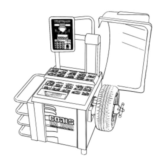
IBS 2000
Interactive Balancing System
1601 J. P . Hennessy Drive, LaVergne, TN USA 37086-3565 615/641-7533 800/688-6359
HENNESSY INDUSTRIES INC. Manufacturer of AMMCO
Service Manual and
Troubleshooting Guide
®
, COATS
®
and BADA
®
Automotive Service Equipment and Tools.
®
Manual Part No.: 9112388 01
Revision:
12/00
Advertisement
Table of Contents

Related Manuals for HENNESSY INDUSTRIES Coats IBS 2000


Summary of Contents for HENNESSY INDUSTRIES Coats IBS 2000
- Page 1 IBS 2000 Interactive Balancing System Service Manual and Troubleshooting Guide 1601 J. P . Hennessy Drive, LaVergne, TN USA 37086-3565 615/641-7533 800/688-6359 Manual Part No.: 9112388 01 HENNESSY INDUSTRIES INC. Manufacturer of AMMCO ® , COATS ® and BADA ®...
- Page 2 Direct Drive ii • Service Manual — COATS Model IBS 2000...
-
Page 3: Table Of Contents
Contents Introduction .......1 Spin and Stop Diagram .....21 Motor Controller Diagram . - Page 4 Safety IMPORTANT SAFETY INSTRUCTIONS READ ALL INSTRUCTIONS Eye and face protection recommendations: 10. Wear proper clothing. Safety toe, non-slip footwear and protective hair covering to contain “Protective eye and face equipment is required to hair is recommended. Do not wear jewelry, loose be used where there is a reasonable probability of clothing, neckties, or gloves when operating the injury that can be prevented by the use of such...
-
Page 5: Introduction
Direct Drive Introduction With the forces known at the planes of the piezos the This service manual contains the functional checks, imbalance forces at the wheel planes can be calculated troubleshooting, adjustment, and part replacement by using the distance from the force transducer planes instructions for COATS ®... -
Page 6: Component Functions & Benefits
Direct Drive Component Functions & Benefits Motor Controller Main CPU* Function: Controls the AC power for the spin and brake Function: Receives data from all input devices (piezos, cycles of the motor. encoder, A/D pots, hoodswitch). Benefit: Solid State Relay (SSR) replaces mechanical Processes the information and sends it to the appropri- contactor. -
Page 7: 2000 Balancer Simplified Block Diagram
Direct Drive 2000 Balancer Simplified Block Diagram Phase Converter or Jumper AC Power Motor Controller On/Off Piezo Motor Interlock Encoder Switch (NO) Closed with hood down Power Supply - 12 Main CPU Display Board Hood Switch (NO) Closed with hood down Manual Start Note: Interlock switch only on models... -
Page 8: Servicing
Direct Drive Servicing 6. Torque Wrench & a 5/16 X 6" hex socket for the torque wrench. Service should be performed only by a factory trained 7. Small Allen wrenches, pot adjusting tools, & a 3/8" COATS ® Service Technician. The troubleshooting and nut driver. -
Page 9: Installation Instructions
Direct Drive Installation Instructions 4. Slide the other nylon bushing into position from the inside, slide on the washer and the retaining ring. Unpacking and Setup 5. Attach the hood spring. The straight end goes at the 1. Remove the staples from around the bottom of the bottom of the machine the hook end into the hood. -
Page 10: Functional Checks
Direct Drive Functional Checks 11. The balancer should now have weight values and position lights displayed. Operational Check 12. Rotate the wheel so the top and bottom position 1. Turn the power switch ON. The display should read LED's for the outside (right) plane are flashing. as follows: 13. -
Page 11: Plane Separation (Accuracy Check)
Direct Drive 10. Position the wheel so the display for the center 6. If the above results are not achieved check the A, position LED on the outside (right) plane is flashing. W, and, D dimensions. The ARM must be OPTIMIZED. Perform the ARM CALIBRATION. -
Page 12: Accuracy Problems
Direct Drive 4. Enter the D value from the tire. It should be within Rotation Check .10 of the reading from the automatic arm, if not the D Note: This procedure must be performed pot should be adjusted (refer to A & D ARM REPAIR with a “Hub Centric”... -
Page 13: Total Accuracy Verification (Tva)
Direct Drive Total Accuracy Verification (TVA) Error Codes Total Accuracy Verification or TAV means that when LED Error Codes the balancer shows zeros in the weight display after When the balancer is powered up, several communi- balancing the wheel it is truly balanced. The model IBS cation checks are made. - Page 14 Direct Drive #8 - Internal Error Code: Displayed at power up when on the motor shaft. Recheck the hubnut or refer to the data on the EE PROM is different than when the “Faceplate Assembly Installation” on pg. 5. Press unit was turned off.
-
Page 15: Troubleshooting Flow Charts
Direct Drive Troubleshooting Flow Charts Pre-diagnostic Pre-diagnostic Check check M a ke s u r e t h e u n i t i s p l u g g e d i n . Tu r n t h e p ow e r o f f, Tu r n t h e p o w e r o n . -
Page 16: Wheel Does Not Spin
Direct Drive Wheel Does Not Wheel does not spin Spin Perform pre- diagnostic check (balancer must be displaying merchandising message to proceed). Replace the motor controller. Check set-up to Enter the Did you enter verify auto-spin is A/W/D wheel on. Attempt to spin parameters? the wheel. -
Page 17: Wheel Does Not Stop
Direct Drive Wheel Does Not Wheel does not stop. Stop Perfor m pre- diagnostic check (balancer must be displaying merchandising message to proceed). Does an error Does wheel Replace the motor Ye s message appear? attempt to stop? controller. Ye s Ye s Cross reference U n p l u g... -
Page 18: No Communications
Direct Drive No Communications Communications Preform pre- diagnostic check (balancer must be displaying merchandising message to proceed). Check for bent Did you replace a prongs, or repostion software chip? the chip. Did this correct the problem? Plug cable in and Check serial cable. -
Page 19: Keypad Problems
Direct Drive Keypad Problems Keypad Problems. Keypad Problems. Keypad Problems. Keypad Problems. Perfor m pre- diagnostic check (balancer must be displaying merchandising message to proceed). Perfor m keypad test Perfor m keypad test Perfor m keypad test Perfor m keypad test Ye s Ye s Ye s... -
Page 20: No Lcd Display
Direct Drive No LCD Display No LCD Display Perfor m pre- diagnostic check (balancer must be displaying Adjust contrast merchandising message to proceed). Is LCD display Is display blank? completely dark?. Adjust contrast. Turn Power Off. Hold down the first rim key while Are LED's tur ning the power Is display... -
Page 21: Lcd Contrast Won't Adjust
Direct Drive LCD Contrast Won’t Adjust Contrast won't adjust Perfor m pre- diagnostic check (balancer must be displaying R e p l a c e C P U merchandising message to proceed). Ye s Disconnect Check -12 vdc on Refer to DC wiring P10 (power) on the power suppy. -
Page 22: No Lcd Back-Light
Direct Drive No LCD Back-Light No LCD Back-light Preform pre- diagnostic check (balancer must be displaying merchandising message to proceed). Is LED backlight Plug cable in and cable plugged in? recheck. Check for Replace display 4 vdc P4-2 of the board. -
Page 23: No Led Display
Direct Drive No LED Display EE ERR No LED Display EE ERR Perform pre- Do pre-diagnostic diagnostic check c h e ck (balancer must be (balancer must be displaying merchandising displaying message to proceed). merchandising message to proceed). Does LCD Troubleshoot LCD. -
Page 24: A & D Arm Problems
Direct Drive A & D Arm A/D ARM PROBLEMS Keypad Problems. Keypad Problems. Keypad Problems. Problems See KEYPAD flow chart. Perform pre- diagnostic check. Check Potentiometer Troubleshooting adjustments. See Return the arm to Is the ar m in HOME complete. A R M HOME. -
Page 25: Diagnostic Procedures Motor And Motor Controller Checking Procedure
Direct Drive Diagnostic Procedures 1. Check for 5 vdc on the CPU location P12/CON- TROL pins 1, 3 and 6 (Tabs 2, 4 and 7 of the Modapt Motor and Motor Controller Checking Adapter). If Voltage is not present refer to the DC volt- Procedure age checks. -
Page 26: Motor Controller Diagram
Direct Drive Motor Controller Diagram 22 • Service Manual — COATS Model IBS 2000... -
Page 27: Optical Encoder Checking Procedure
Direct Drive Optical Encoder Checking Procedure Piezo Output Test This procedure allows you to check the optical This procedure allows you to look at the piezo output encoder to determine if it is operating properly. A readings to diagnose a problem with any of the piezos. defective encoder can result in spin or braking prob- Piezo problems can cause incorrect weight readings lems. -
Page 28: Piezo Crystal Checking Procedure
Direct Drive Piezo Crystal Checking Procedure Balancer Display Diagnostics This procedure details how to check for an “upside This is a diagnostic menu that should only be down” piezo assembly (the crystal has been assem- accessed by authorized Hennessy service personnel. It bled upside down inside the piezo assembly). -
Page 29: Replacement Procedures For Model Ibs 2000 Balancer
Direct Drive Parts Replacement Procedures for 11. Plug balancer in. Model IBS 2000 Balancer 12. Perform FUNCTION CHECKS. The procedures in this section will aid in replacing Caution! If the (red) start switch wire P8 and major subassemblies of the IBS 2000 balancer. the (grey) LCD backlight wire P4 are not con- nected in the correct location of the Display Do not disassemble, adjust or replace any part before... -
Page 30: Lcd Board Replacement
Direct Drive LCD Board Replacement Hood Magnet Replacement Caution! This is a liquid crystal display do not 1. Remove the rubber hood stop from the hood bracket bend or apply direct pressure. Store in a static on the chassis. bag at temperatures between 32° F - 95° F. Do 2. -
Page 31: Circuit Breaker Replacement
Direct Drive 3. Squeeze the retainers on the switch and push it 3. Disconnect the incoming power from T1 of the MC through the opening in the accessory column. board. If single phase, disconnect the capacitor from P4 of the MC board. 4. -
Page 32: Fan Motor Assembly Replacement
Direct Drive Fan Motor Assembly Replacement 7. Install new optical encoder. 1. Unplug the balancer. 8. Install rotary shutter. 2. Remove weight tray and weight tray shield. 9. Install rear end bell. 3. Disconnect fan motor plug from P1 of the Motor 10. -
Page 33: Faceplate & Shaft Assembly Replacement
Direct Drive 20. Tighten the nyloc nuts until the distance from the Piezo Assembly Replacement top of the motor cradle to top of the piezo spring retainer Note: The piezo assemblies used in the IBS is two (2) inches. 2000 are different from the other Coats bal- ancers in that they have a 6 pin phone cable 21. -
Page 34: Capacitor Assembly Replacement
Direct Drive Capacitor Assembly Replacement A/D Arm Repair And Replacement 1. Unplug the balancer. The IBS 2000 uses an automatic Distance A and 2. Remove weight tray and weight tray shield. Diameter D Gauge Assembly, however it is different from the 1050. The arm assembly is repairable and you 3. -
Page 35: Small D Gear Assembly Replacement
Direct Drive 2. Remove the weight tray and weight tray shield. Large D Gear Replacement 1. Unplug the balancer. 3. Unplug the arm cable from P7 (Inner Arm) of the CPU board. 2. Remove the weight tray and weight tray shield. 4. -
Page 36: Ibs 2000 Wiring Diagrams
Direct Drive IBS 2000 Wiring Diagrams 32 • Service Manual — COATS Model IBS 2000... - Page 37 Direct Drive Service Manual — COATS Model IBS 2000 • 33...
- Page 38 Direct Drive 34 • Service Manual — COATS Model IBS 2000...
- Page 39 Direct Drive Service Manual — COATS Model IBS 2000 • 35...
- Page 40 9112388 01 12/00 © Copyright 1998 Hennessy Industries and COATS All Rights Reserved Printed in USA...
Need help?
Do you have a question about the Coats IBS 2000 and is the answer not in the manual?
Questions and answers