Table of Contents
Advertisement
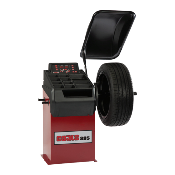
885 Wheel Balancer
See
Balancing Your
First Tire
on page 1.
1601 J. P . Hennessy Drive, La Vergne, TN USA 37086 615/641-7533 800/688-6359
HENNESSY INDUSTRIES LLC Manufacturer of COATS®, AMMCO® and BADA® Automotive Service Equipment and Tools.
Safety Instructions
Set Up Instructions
Operation Instructions
Maintenance Instructions
READ these instructions before placing unit in
service. KEEP these and other materials delivered
with the unit in a binder near the machine for ease
of reference by supervisors and operators.
www.coatsgarage.com
Manual Part No.: 85611582 00
Revision:
05/19
Advertisement
Table of Contents

Subscribe to Our Youtube Channel
Related Manuals for HENNESSY INDUSTRIES Coats 885


Summary of Contents for HENNESSY INDUSTRIES Coats 885
- Page 1 Manual Part No.: 85611582 00 1601 J. P . Hennessy Drive, La Vergne, TN USA 37086 615/641-7533 800/688-6359 www.coatsgarage.com Revision: 05/19 HENNESSY INDUSTRIES LLC Manufacturer of COATS®, AMMCO® and BADA® Automotive Service Equipment and Tools.
- Page 2 NOTICE Read entire manual before assembling, installing, operating, or servicing this equipment. ii • Important: Always read and follow the instructions.
-
Page 3: Table Of Contents
Table of Contents Important Safety Instructions..iv - vi Setup............16 Owner’s Responsibility........v Menu Access Diagram.........16 Operator Protective Equipment......v Self-Diagnostics.............17 Definitions of Hazard Levels......v Balancing Machine Calibration........17 Safety Notices and Decals.......vi Automatic Gages Calibration.....18 Standard Safety Devices........vi Distance Gauge Calibration........18 Diameter Gauge Calibration........19 *Balancing Your First Tire........1 Adhesive Weight Width........20 Principle Operating Parts........2... -
Page 4: Important Safety Instructions
IMPORTANT SAFETY INSTRUCTIONS READ ALL INSTRUCTIONS 10. Keep work area clean and well lighted. Cluttered Eye and face protection recommendations: and/or dark areas invite accidents. “Protective eye and face equipment is required to 11. Avoid dangerous environments. Do not use power be used where there is a reasonable probability of tools or electrical equipment in damp or wet loca- injury that can be prevented by the use of such... -
Page 5: Owner's Responsibility
Owner’s Responsibility Definitions of Hazard Levels To maintain machine and user safety, the responsibil- Identify the hazard levels used in this manual with the ity of the owner is to read and follow these instruc- following definitions and signal words: tions: DANGER •... -
Page 6: Safety Notices And Decals
For additional copies of either, or further information, con- tact: Hennessy Industries, Inc. 1601 J.P . Hennessy Drive LaVergne, TN 37086-3565 (615) 641-7533 or (800) 688-6359 www.coatsgarage.com Standard Safety Devices •... -
Page 7: Balancing Your First Tire
Balancing Your First Tire 1. Turn the machine OFF then ON 7. Raise hood after tire stops rotat- (resets machine). ing. Note: The machine wakes up using standard Note: Wait for wheel to stop before raising the clip-on wheel weight locations (c1 & c2) and hood. -
Page 8: Principle Operating Parts
Principle Operating Parts Know Your Unit Compare this illustration with the unit before placing ✓ it into service. Maximum performance and safety will Do It Now! be obtained only when all persons using the unit are Now is a good time fully trained in its parts and operation. -
Page 9: Power Switch
Note: Throughout this manual wheel weights are Power Switch referred to as Clip-on or Tape-A-Weight™. Figure 3 The ON/OFF switch is located on the back of the shows an example of each weight. balancer. ON/OFF Power Switch Clip-on Weight Tape-A-Weight™ Corrective Weight Examples: For Best Results, use BADA ®... -
Page 10: Operating The Balancer
Standard Back Cone/Collet Mounting Operating the Balancer Most original equipment and steel wheels can be Mounting Wheel on Balancer Shaft mounted properly using this method. The wheel is cen- tered on a cone from the inner side of the hub. CAUTION 1. -
Page 11: Optional Front Cone/Collet Mounting
Alternate Mounting Optional Front Cone/Collet Mounting If the wheel has a protruding outer hub which will not A wheel should be centered by the outer side of the permit the use of the pressure cup, or the cup will not hub only when the inner surface will not provide an permit the hub nut to engage at least four turns of the accurate surface to center on. -
Page 12: Control Panel And Display
Control Panel And Display Digital readouts, AMOUNT OF UNBALANCE, inside/outside/static Push button, unbalance reading below the threshold Digital readouts, POSITION OF UNBALANCE, inside/outside/static Push button, selection of correction mode Push button, unbalance reading Push button, FUNCTIONS MENU Push button, menu selection confirmation Push button, cycle start Push button, emergency/home Push button, position repeater... -
Page 13: Operation Functions Menu
Operation Functions Menu Use of the Wheel Balancer STANDARD BALANCING (clip-on counterweights) Wheel dimensions setting 1. Using the special grip, move the end of gauge against the rim as shown in the figure: 2. While the gauge is moving the following appears: 3. - Page 14 Page left intentionally blank. 8 • Important: Always read and follow the instructions.
-
Page 15: Result Of The Measurement And Weight Application
Result of the measurement and weight application If the unbalance is out of tolerance: 1. When the spin is complete, bring the unbalance into correction position by turning the wheel by hand. The spindle is automatically locked in correction position (if not disabled the wheel lock and for rotation speeds less than 20 rpm). -
Page 16: Balancing With Adhesive Weights (Alu)
BALANCING WITH ADHESIVE WEIGHTS (ALU) Wheel dimensions setting Using the dedicated grip, move the gauge tip up against the inside of the rim and make two consecutive measure- ments starting from the inside (FI) as shown in the figure. The two preselected positions coincide with the point where the counterweight is to be applied. -
Page 17: Result Of The Measurement And Weight Application
Result of the measurement and weight application If the unbalance is out of tolerance: 1. When the spin is complete, bring the unbalance into correction position by turning the wheel by hand. The spindle is automatically locked in correction position (if not disabled the wheel lock and for rotation speeds less than 20 rpm) If the acoustic signal is enabled ( ), a beep will sound when the correction... -
Page 18: Balancing With A Mix Of Adhesive And Clip-On Weights And Static Balancing
BALANCING WITH A MIX OF ADHESIVE AND CLIP-ON WEIGHTS AND STATIC BALANCING After dimension acquisition in standard balancing mode, pressing the buttons you can select one of the following correction modes. WEIGHT APPLICATION POSITION Correction type Inside Outside Clip-on weight at 12 o’clock Clip-on weight at 12 o’clock Clip-on weight at 12 o’clock Adhesive weight at 12 o’clock... -
Page 19: Static Unbalance
STATIC UNBALANCE The static unbalance is shown on display (1) and the relative correction position on the LED display. Note: Must press the button to show Static. The correction weight application diameter cannot be set, but is deduced from the dimensions acquired in standard or ALU mode through interpolation algorithms and the use of fixed parameters. -
Page 20: Hide The Adhesive Weights (Behind Spoke)
HIDE THE ADHESIVE WEIGHTS (Behind Spoke) Behind Spoke is only possible in the event of static unbalance or ALU external side and is used to hide any adhesive weights correcting unbalance behind the rim spokes. 1. Perform an unbalance measurement spin. 2. -
Page 21: Unbalance Match Mount Balance
Unbalance Match Mount Balance The program allows total wheel out-of-balance to be reduced by compensating, when possible, tire and rim out-of-balance values. It is suitable for static unbalance values in excess of 30 grams. It requires two runs, rotating the tire on the rim on the second run. 1. -
Page 22: Setup
Setup MENU ACCESS DIAGRAM This is used to personalize some balancer functions and to perform calibrations. To access this section, press the button. UNBALANCE OPTIMISATION WHEEL DIMENSIONS SETTING diameter mm/inch width mm/inch start from guard closing ON/OFF approximates 1-5g 0.1-0.25oz beep signal ON/OFF SELF-DIAGNOSTICS... -
Page 23: Self-Diagnostics
SELF-DIAGNOSTICS The machine can perform self-diagnostics to check the LED’s on the control panel and make sure the encoder reads correctly. To perform this operation, view the SETUP menu. In the self-diagnostics sequence, all the LED’s on the panel light up for a few seconds in order to check operation. -
Page 24: Automatic Gages Calibration
3. Shift the standard weight from the outside to the inside keeping the same position. Close the guard and press the button to perform a spin. 4. Turn the wheel until the Cal weight is at the top (12 o’clock) and press 5. -
Page 25: Diameter Gauge Calibration
Use and maintenance manual 3. Move the distance gauge pusher in line with the Face Plate and press Face Plate CALIBRATION COMPLETE ▪ Return the gauge to home position. ▪ The wheel balancer is ready for operation. “r.P.”: In the event of errors or faulty operation, the writing appears on the display : shift the gauge to the Home position and repeat the calibration operation exactly as described above. -
Page 26: Adhesive Weight Width
3. Turn the gauge downward positioning the gauge rod in contact with the spindle sleeve (P.2, Position 2) as shown in the figure and press Gauge Rod touches the bottom of the Spindle Sleeve here CALIBRATION COMPLETE ▪ Return the gauge to home position. ▪... -
Page 27: Diagnostics
Diagnostics INCONSISTENT UNBALANCE READINGS In some cases, when a wheel that has just been balanced is repositioned on the balancer, the machine can detect an unbalance. This is not a machine problem but is due to faulty mounting of the wheel on the flange. In other words, when mounting the wheel after initial balancing, it has taken another position with respect to the balancer shaft axis. - Page 28 ▪ Err. 11 Speed too high error Check in self-diagnostics that the encoder functions properly ▪ During unbalance measurement rotation, Replace the computer board wheel speed is more than 270 rpm ▪ Err.14 / Unbalance measurement error Check in self-diagnostics that the encoder functions properly Err.15 / ▪...
-
Page 29: Installation Instructions
Installation Instructions Features • Balances Most Automotive Wheels A factory trained COATS ® Service Technician must perform the install, setup, and initial test procedures • Single-Spin Dynamic Two-Plane or Static Balancing on your wheel balancer. Do not attempt to install and •... -
Page 30: Floor And Space Requirements
Floor and Space Requirements The balancer must be located on a flat floor of solid construction, preferably concrete. The balancer must sit solidly on its three feet. If the balancer is not level, does not sit solidly on its three feet, or is placed on an unstable floor, the balancer will not function properly and may produce inaccurate balance readings. -
Page 31: Unpacking The Unit
Unpacking the Unit 1. Remove the shipping carton from the pallet. Fig. 1 2. Remove all loose parts and accessories packed around the unit. Remove Balancer from Pallet 3. Remove the shipping bolts that hold the balancer to the pallet. CAUTION Fig. - Page 32 NOTES 85611582 00 05/19 © Copyright 2019 Hennessy Industries and COATS All Rights Reserved Printed in USA...
Need help?
Do you have a question about the Coats 885 and is the answer not in the manual?
Questions and answers