Table of Contents
Advertisement
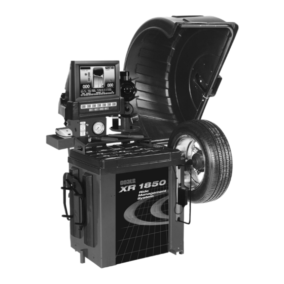
XR 1800/1850 Series
Wheel Balancer
See
Balancing
Your First Tire
on page 2.
1601 J. P . Hennessy Drive, LaVergne, TN USA 37086-3565 615/641-7533 800/688-6359 www.ammcoats.com
HENNESSY INDUSTRIES INC. Manufacturer of AMMCO
Installation Instructions
Operating Instructions
Safety Instructions
Maintenance Instructions
READ these instructions before placing unit in
service KEEP these and other materials delivered
with the unit in a binder near the machine for
ease of reference by supervisors and operators.
®
, COATS
®
and BADA
®
Automotive Service Equipment and Tools.
®
Manual Part No.: 8113423 07
Revision:
01/07
Advertisement
Table of Contents

Subscribe to Our Youtube Channel
Related Manuals for HENNESSY INDUSTRIES Coats XR 1850 Series


Summary of Contents for HENNESSY INDUSTRIES Coats XR 1850 Series
- Page 1 1601 J. P . Hennessy Drive, LaVergne, TN USA 37086-3565 615/641-7533 800/688-6359 www.ammcoats.com Manual Part No.: 8113423 07 HENNESSY INDUSTRIES INC. Manufacturer of AMMCO ® , COATS ®...
- Page 2 Safety IMPORTANT SAFETY INSTRUCTIONS READ ALL INSTRUCTIONS 10. Wear proper clothing. Safety toe, non-slip Eye and face protection recommendations: footwear and protective hair covering to contain “Protective eye and face equipment is required to hair is recommended. Do not wear jewelry, loose be used where there is a reasonable probability of clothing, neckties, or gloves when operating the injury that can be prevented by the use of such...
-
Page 3: Owner's Responsibility
Safety Owner’s Responsibility Definitions of Hazard Levels To maintain machine and user safety, the responsibil- Identify the hazard levels used in this manual with the ity of the owner is to read and follow these instruc- following definitions and signal words: tions: DANGER •... -
Page 4: Safety Notices And Decals
For additional copies of either, or further exposure. information, contact: There are NO service procedures or adjust- Hennessy Industries, Inc. ments which can be performed on the laser 1601 J.P . Hennessy Drive in this product. LaVergne, TN 37086-3565... -
Page 5: Standard Safety Devices
Safety Standard Safety Devices • Stop key for stopping the wheel under emergency conditions. • A hood guard of high impact plastic that is designed to prevent the counterweights from flying out in any direction except towards the floor. • A hood switch interlock system that prevents the machine from starting if the guard is not lowered and stops the wheel whenever the guard is raised. - Page 6 Safety NOTICE Read entire manual before assembling, installing, operating, or servicing this equipment. vi • Important: Always read and follow the on-screen operating instructions.
-
Page 7: Table Of Contents
Contents T T a a b b l l e e o o f f C C o o n n t t e e n n t t s s I I m m p p o o r r t t a a n n t t S S a a f f e e t t y y I I n n s s t t r r u u c c t t i i o o n n s s ......i i i i M M o o u u n n t t i i n n g g W W h h e e e e l l o o n n S S p p i i n n d d l l e e S S h h a a f f t t . -
Page 8: B B A A L L A A N N C C I I N N G G Y Y O O U U R R F F I I R R S S T T T T I I R R E
Video Balancer B B a a l l a a n n c c i i n n g g Y Y o o u u r r F F i i r r s s t t T T i i r r e e Important: Always read and follow the on-screen 8. -
Page 9: Important: Always Read And Follow The On-Screen Operating Instructions
Video Balancer Note: To reset the mode back to the initial screen at any time, press the DYNAMIC option or press the key, or turn the machine OFF then ON. Note that MENU if an operator is in a balance mode, it may be neces- sary to finish the balance cycle first. -
Page 10: Important: Always Read And Follow The On-Screen Operating Instructions
Video Balancer P P r r i i n n c c i i p p l l e e O O p p e e r r a a t t i i n n g g P P a a r r t t s s Monitor Touch Panel Portable Sliding... -
Page 11: Important: Always Read And Follow The On-Screen Operating Instructions
Video Balancer Tool Accessory Storage Tilting Monitor Adjustment Knobs Tire Width Sensor (measures when hood is lowered) Inflate Button Printer Manual Tire Bleed Valve Adjustable Captured Air Gauge Cone Spring Weight Tray with Dual Pockets for Weights thru 2 oz. - Deep Pockets thru 4 oz. -
Page 12: Power Switch
Video Balancer Power Switch Positioning Pedal The ON/OFF decal, see figure 4, indicates the loca- Use the positioning pedal to hold the wheel position tion of the ON/OFF switch at the back of the balancer. during weight application, as shown in figure 5. The circuit breaker reset button is also at this location. -
Page 13: Using The Offset Arm
Video Balancer Using the Offset Arm To measure for a hidden weight location, place the offset arm at a hidden weight placement location as When prompted by the on-screen instructions, use shown in figure 8. the offset arm, see figure 6, to enter A & D measure- ments automatically. -
Page 14: Sensor Measuring Systems
Video Balancer Sensor Measuring Systems The sensor, shown in figure 12, is mounted on an adjustable slide at rear of machine and is used to By lowering the hood, measure wheel width auto- measure radial runout of the tire when the eye of the matically using the Tire Width Sensor. -
Page 15: Printer
Video Balancer Printer Option CORRECTED - operator uses this area to Use the printer, on especially equipped models, manually check either YES if runout was corrected or (shown in figure 14) to provide a BALANCER CERTIFI- N.R. if not required. CATE for the wheel balance service. -
Page 16: U U N N D D E E R R S S T T A A N N D D I I N N G G T T H H E E
Video Balancer U U n n d d e e r r s s t t a a n n d d i i n n g g t t h h e e 4. Refer to the Mode Icon in the upper right hand corner of the screen for mode and weight placement V V i i d d e e o o D D i i s s p p l l a a y y S S c c r r e e e e n n s s... -
Page 17: Monitor And Initial Screen Feature Reference
Video Balancer Monitor and Initial Screen Feature Reference RO Max. (Instant Reading of Wheel Runout) * Profile Tire Image Operator Display Mode Icon Static-on-Screen™ Econo Balance Centering Bar Mode Icon Static Unbalance Icon (appears when over 1.1 oz is present) Weight Weight Placement... -
Page 18: Menu Screen Flowchart
Video Balancer Menu Screen Flowchart MENU Press the key for the Menu screen to access balancer function screens and to set configuration screens. See the flowchart below. Menu See page 16 for additional Optimization (Match Balance) Cycle History information. Runout (Runout Match) Spins between calibrations 1000 Cycle History Service Adjustments... -
Page 19: Important: Always Read And Follow The On-Screen Operating Instructions
Video Balancer See page 21 Distance Arm Calibration Optimization for additional information. (Match Balance) On-screen Instructions On-screen Instructions Width Sonar Calibration See page 22 Graph Screen for additional On-screen Instructions information. On-screen Instructions Diameter Arm Calibration Service Adjustments On-screen Instructions Distance Arm Calibration Width Sonar Calibration Diameter Arm Calibration... -
Page 20: Menu Screen Flowchart
Video Balancer B B a a l l a a n n c c e e r r F F u u n n c c t t i i o o n n S S e e t t - - Printer - Toggle ON or OFF to set the printer, owner address, spin no., operator no., vehicle tag u u p p a a n n d d R R e e v v i i e e w... -
Page 21: Balancing Set-Up
Video Balancer Select RUNOUT LIMITS option for runout menu: Calculation Roundoff - Toggles the display of wei ght corrections roundoff from 0.25 OZ (most whe Max. True Runout Limit - Tolerance els) to 0.50 OZ (heavy wheels). that indicates the limit of runout allowed on the tire/wheel. -
Page 22: Additional Functions
Video Balancer A d d v v a a n n c c e e d d B B a a l l a a n n c c i i n n g g Machine Self-Test - Provides software version, technical, and other machine diagnostic informa- F F u u n n c c t t i i o o n n s s tion (DIAGNOSTIC PROCEDURES section page... -
Page 23: Dynamic Modes
Video Balancer Dynamic Modes Check-Spin - press to save 2 to 3 seconds of time when a balancing wheel. This option elimi- Clip-on Weights - the initial screen. This mode is nates the runout measurement during the Check- used for most passenger and light truck tire assem- Spin. -
Page 24: Static Modes
Video Balancer Static Modes WARNING Choose a static balance for wheel assemblies that are not possible to balance dynamically or for narrow The Patch Weight Balance involves the loos- wheels. For example, a motorcycle wheel that has a ening of tire beads and the inflation of a tire. small wheel width. -
Page 25: Additional Options
Video Balancer Additional Options Unspoke - If you decide not to use the spoke option, press this option. Only one right side Be aware of the following options that appear on marker (ball) will display. selected screens. Press the numbered key that corre- sponds with the key icon for each additional option Printer - (available in 3D view) prints a certificate described below. -
Page 26: Automatic Runout Detection
Video Balancer M a a t t c c h h i i n n g g Automatic Runout Detection The wheel balancer software can be set to automati- WARNING cally detect a wheel assembly that exceeds the static limit unbalance or radial runout limit. A Runout Diagnostic screen will appear, see figure 36, that pro- A matching procedure may involve the loos- vides on-screen information for the operator. -
Page 27: Optimization (Match Balance)
Video Balancer Optimization (Match Balance) The Tire/Rim Weight Optimization procedure is used to determine the best mating of tire and rim that will result in the least amount of total unbalance of the assembly. It requires two spins and two rotations of the tire on the rim. -
Page 28: Runout (Runout Match)
Video Balancer Runout (Runout Match) place. Do not place the offset arm at the clip-on weight location. Select the button and then the RUNOUT MENU (RUNOUT MATCHING) option or, if the wheel bal- 3. Press and turn the wheel slowly. START ancer software is set to automatically detect runout, Note: Hold the offset arm in place one revolution until... -
Page 29: Important: Always Read And Follow The On-Screen Operating Instructions
Video Balancer M a a n n u u a a l l l l y y S S e e t t t t i i n n g g W W h h e e e e l l When necessary, the wheel dimensions can be inserted or edited in manual mode. -
Page 30: Standard Back Cone Mounting
Video Balancer M o o u u n n t t i i n n g g W W h h e e e e l l o o n n Standard Back Cone Mounting S S p p i i n n d d l l e e S S h h a a f f t t Most original equipment and steel wheels can be mounted properly using this method. -
Page 31: Standard Front Cone Mounting
Video Balancer Standard Front Cone Mounting Alternate Mounting A wheel should be centered by the outer side of the If the wheel has a protruding outer hub which will not hub only when the inner surface will not provide an permit the use of the pressure cup, or the cup will not accurate surface to center on. -
Page 32: Machine Self-Calibration
Video Balancer M a a c c h h i i n n e e S S e e l l f f - - c c a a l l i i b b r r a a t t i i o o n n 7. -
Page 33: Service Adjustments
Video Balancer Service Adjustments Distance Arm Calibration Note: Calibrate the offset arm first, since it is very Press the MENU key and select SERVICE ADJUST- important that the wheel dimensions are correct. MENTS option for the following menu selections. Follow these instructions on-screen when calibrating Important: These service adjustments are password the DISTANCE ARM CALIBRATION option protected. -
Page 34: Diameter Arm Calibration (Plastic)
Video Balancer Note: The sonar calibration target bracket is stored flush with the side of cabinet at all other times, see fig- ure 51. Calibration Target Bracket in Stored Position Figure 49B - Metal Offset Arm Gauge to Faceplate 2. Return offset arm to home position. Figure 51- Sonar Target Bracket in Stored Position 3. -
Page 35: Diameter Arm Calibration (Metal)
Video Balancer Diameter Arm Calibration (Metal) D i i a a g g n n o o s s t t i i c c P P r r o o c c e e d d u u r r e e s s Note: Be sure the correct Distance/Diameter Arm After Balance Vibration Problems Type is set (See Service Adjustments page 27). -
Page 36: Troubleshooting
Video Balancer Troubleshooting A COATS ® Service Technician may ask for information to help diagnose service concerns. Conveying this information to your service technician prior to servicing can help to expedite service to your equipment. Although much of the diagnostic information aids your COATS ®... - Page 37 Video Balancer Error Symptom Check Err. 3 Calculation Error. 1. Check the wheel dimensions setting. Incorrect Machine Self- 2. Check the piezo pick-ups connections - electrical & mechanical. (in Calibration. MACHINE SELF-TEST, push on spindle shaft and verify that both piezo outputs change.
- Page 38 Video Balancer Error Symptom Check Err.13 Error in the unbalance measure- 1. Press EXIT and respin. Check PHASE, VCO, VCI in MACHINE SELF-TEST . Err.14 ment. 2. Check the piezo pick-ups connection. (electrical & mechanical) Err.17 3. Check the balancer spindle connections. Err.18 4.
- Page 39 Video Balancer Error Symptom Check Err.55 Error in the Sonar reading. 1. Before taking the measurement, make sure that the RADIAL The values taken by the Sonar RUNOUT SONAR is properly positioned. are insufficient for a correct 2. Check that the wheel doesn’t stop before making at least 4 to 5 runout measurement.
-
Page 40: Machine Self-Test "Green Screen
Video Balancer Machine Self-Test “Green Screen” A - This line provides software version and other tech- nical information. In the event of faulty wheel balancer operation, notify a COATS ® Service Technician of all the machine self B (Pos.) - An encoder check. The word UP should test readings. -
Page 41: Monitor Screen Adjustment
Video Balancer M a a i i n n t t e e n n a a n n c c e e Monitor Screen Adjustment The monitor control panel buttons are located on the I I n n s s t t r r u u c c t t i i o o n n s s monitor. -
Page 42: Receiving
Video Balancer I I n n s s t t a a l l l l a a t t i i o o n n I I n n s s t t r r u u c c t t i i o o n n s s Electrical Requirements The wheel balancer requires a 115 VAC, 60HZ, single- Receiving... -
Page 43: Floor And Space Requirements
Video Balancer Floor and Space Requirements The balancer must be located on a flat floor of solid construction, preferably concrete. The balancer must sit solidly on its three feet. If the balancer is not level, does not sit solidly on its three feet, or is placed on an unstable floor, the balancer will not function properly and may produce inaccurate balance readings. -
Page 44: S S P P E E C C I I F F I I C C A A T T I I O O N N S
Video Balancer S S p p e e c c i i f f i i c c a a t t i i o o n n s s F F e e a a t t u u r r e e s s Cycle Time •... -
Page 45: R R E E Q Q U U I I R R E E D D A A C C C C E E S S S S O O R R I I E E S
Video Balancer R R e e q q u u i i r r e e d d A A c c c c e e s s s s o o r r i i e e s s O p p t t i i o o n n a a l l A A c c c c e e s s s s o o r r i i e e s s •... - Page 46 Video Balancer N o o t t e e s s 40 • Important: Always read and follow the on-screen operating instructions.
- Page 47 Video Balancer G l l o o s s s s a a r r y y o o f f T T e e r r m m s s BDC - an acronym for bottom-dead-center, also referred to as the 6 o’clock position. Dynamic Balance - balancing a wheel using two planes for correction.
- Page 48 8113423 07 01/07 © Copyright 2002 Hennessy Industries and COATS All Rights Reserved Printed in USA...
Need help?
Do you have a question about the Coats XR 1850 Series and is the answer not in the manual?
Questions and answers