Table of Contents
Advertisement
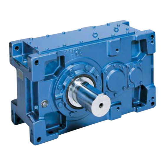
PARAMAX
9000 Series
CAUTION
These products should be handled, installed, and maintained by trained technicians.
Carefully read the maintenance manual before use.
Oil is removed from these products before shipment. Supply oil according to the
maintenance manual before operation.
A copy of this maintenance manual should be sent to the actual user.
This maintenance manual should be kept by the user for future reference.
®
Maintenance Manual
No.GM2002E-8
Advertisement
Table of Contents

Related Manuals for Sumitomo PARAMAX 9000 Series


Summary of Contents for Sumitomo PARAMAX 9000 Series
- Page 1 PARAMAX ® 9000 Series CAUTION These products should be handled, installed, and maintained by trained technicians. Carefully read the maintenance manual before use. Oil is removed from these products before shipment. Supply oil according to the maintenance manual before operation. A copy of this maintenance manual should be sent to the actual user.
- Page 2 Introduction and Safety · Read these instructions and all accompanying documents carefully prior to installing, starting, operating, inspecting, and maintaining this equipment in any region worldwide. The equipment must meet all conditions relating to safety as noted in this instruction prior to starting and operating. These instructions must always be kept close to this equipment's operating location or directly with the product.
-
Page 3: Table Of Contents
• Each page in this manual is identified with an icon in the upper right corner. Each icon identifies the relevant product type of the information on the page . For example, each page in this manual will provide information related to: reducers only, drive units only, or common information relating to all units. -
Page 4: Inspection Upon Delivery
COMMON 1. Inspection upon delivery CAUTION • Unpack the unit after verifying that it is positioned right side up; otherwise, injury may result. • Verify that the unit received is exactly the ordered item. When a different product is installed, injury or damage to the system may result. - Page 5 COMMON 1-2) Nomenclature (1) Drive unit or Reducer PARAMAX 9075 35.5 Nominal reduction Auxiliary type ratio Refre to Table 5 Auxiliary type Number of gear stage Refer to Table 9 Refer to Table 4 Slow-speed shaft type Assembly Refer to Table 8 Refer to Table 3 Slow-speed shaft arrangement...
- Page 6 COMMON (2) Type of motor Respective codes and motor nomenclature are shown. Please check to see if the type of Paramax Drive or Reducer you have conforms to your order. Motor Nomenclature Standards . Regulations Mounting method Foot Premium-efficiency motor Blank Flange High-efficiency motor (IEC standard)
-
Page 7: Storage
COMMON 2. Storage Store PARAMAX DRIVE for extended periods of time in accordance with instructions 2-1, 2-2 and 2-3 below. 2-1) Storage Location Store PARAMAX DRIVE indoors in a clean, dry, covered storage area. • Do not store PARAMAX DRIVE outdoors, in humidity, dust, extreme temperature fluctuation, corrosive gas, or similar atmosphere. -
Page 8: Installation
COMMON 4. Installation DANGER • Do not use a standard unit in an explosive atmosphere; electric shock, personal injury, explosion, fire or damage to the equipment may occur. • When an explosion-proof type motor is installed, use a motor with specifications compliant with dangerous locations (where an explosive atmosphere of gas or vapor may be generated);... - Page 9 COMMON 4-3) Installation method for PARAMAX with fan (Parallel shaft) CAUTION • Be careful for injuries with sharp edges of keyways and parts. • Keep accessories together to prevent losing during installation. • Handle parts carefully to prevent damage. Avoid water and dust. Reducer installation procedure (1) Remove bolt 1.
- Page 10 COMMON 4-4) Instructions to ensure the cooling air flow To ensure the air flow from a fan rotor, please follow this instructions. (1) Ensure the air intake For PARAMAX DRIVE with a fan rotor, make more than 15mm gap between a fan hood and a screen (ex.
-
Page 11: Coupling With Other Machines
COMMON 5. Coupling with other machines CAUTION CAUTION • Confirm the direction of rotation before coupling PARAMAX DRIVE with its driven machine. Difference in the direction of rotation may cause injury or damage to the system. • Remove the key temporarily attached to the output shaft of PARAMAX DRIVE when the shaft is free-rotating (i.e. - Page 12 COMMON 5-2) Hollow shaft Hollow shaft 5-2-1) Shrink disc type The shrink disc has a keyless shrink fit mechanism which Thrust washer shrinks the hollow shaft of a reducer mechanically through Driven shaft the tightening locking bolt, and holds the driven shaft and the hollow shaft as one fixture.
- Page 13 COMMON 5-2-2) Key way connection Size 9015 to 9055 Mounting procedure (Fig.18) ( d ) ( e ) The Hollow shaft bore is provided with retaining ring (d). ( c) Ring (d) is the essential component for mounting, securing, ( b ) ( a ) and removing the unit.
- Page 14 COMMON 5-2-3) Torque arm (The torque arm is optional.) The hollow shaft reducer is fixed by the torque arm to prevent the reducer from revolving by an opposite reaction force. Reducer Fig.26 shows the construction of a standard torque arm. Select a torque arm support with proper construction and strength, taking into consideration the reaction force of the reducer and the impact load.
- Page 15 COMMON 5-2-5) Hollow shaft dimensions (key type) 9015~9055 9060~9085 L / 2 L / 2 LR(45 ) B - B DETAIL A Fig.28 Table 13 Hollow shaft dimensions (key type) Unit: mm Locking Locking distance Hollow shaft Driven shaft Safety cover screw (f) ring (h) Size...
-
Page 16: Wiring
6. Wiring • This manual shows wiring for motors with Japanese standard specifications. Please consult with us for motors with overseas specifications. DANGER • Do not handle the unit when electric power is applied. Be sure to turn off the power; electric shock may occur. •... - Page 17 6-1) Measurement of insulation resistance • When measuring the insulation resistance, disconnect the motor from the control panel. Measure the insulation resistance before connecting to power source. The insulation resistance (R) varies according to the motor output, voltage, type of insulation, coil temperature, humidity, dirt, period of operation, test duration, etc. Insulation resistance should exceed the values shown in Table 14 in most cases.
- Page 18 6-3) Motor Connection Shows the motor connection and the standard specifications for terminal codes. Fig.29 Without brake, 3-phase power source In a case of three lead wires In a case of six lead wires (Star(Wye)-Delta connection) Star connection for starting Delta connection after starting Control panel...
- Page 19 6-4) Fig.30 Without brake, Inverter drive In a case of three lead wires In a case of six lead wires Inverter Inverter U V W U V W Control panel Control panel Terminal box Terminal box U1 V1 W1 U V W Motor V2 W2 U2 Motor...
-
Page 20: Operation
COMMON 7. Operation DANGER • Do not touch rotating parts (output shaft, etc.) during operation; loose clothing may become caught in these rotating parts and cause serious injury or death. • When the power supply is interrupted, be sure to turn off the power switch. Unexpected resumption of power may cause electric shock, personal injury or damage to the equipment. -
Page 21: Daily Inspection And Maintenance
COMMON 8. Daily Inspection and Maintenance DANGER • Do not handle the unit when connected to the power source. Be sure to turn off the power; possible, electric shock may occur. • Do not touch any rotating parts (output shaft, etc) during maintenance or inspection of the unit; loose clothing may become caught in these rotating parts and cause serious injury or death. - Page 22 COMMON 8-2) Confirmation of lubrication method • Refer to the applicable items regarding maintenance. Unit lifetime may decrease without proper maintenance. (1) Refer to Table 17 to confirm the gear lubrication method for your unit. (2) Table 18 lists pages that can be referenced regarding lubrication maintenance. (3) Refer to table 19 on Page 22 standard input speed.
- Page 23 COMMON Table 19 Standard speed table Input speed r/min Assembly Size 1000 1500 1800 9015 - 9075 9080 - 9085 Horizontal 9095 9105 - 9115 9015 - 9075 Vertical 9080 - 9085 9015 - 9075 Upright 9080 - 9085 9030 - 9095 Horizontal 9100 - 9115 9030 - 9095...
- Page 24 COMMON CAUTION • For equipment with motor oil pump, run the pump prior to starting the drive unit or reducer. Start motor of drive unit or reducer after lubricating oil has circulated through the bearings. Otherwise, the equipment may be damaged. •...
- Page 25 COMMON (4) Oil quantity An estimated quantity of oil for standard specifications is shown in item 12. "oil quantity (Page 34)." The oil quantity shown in the catalog is not exact. Use a dipstick or visible oil gauge to check the oil level. (5) Oil supply Supply oil through the filling port on top of the main unit.
- Page 26 COMMON (7) Positions of grease fitting and discharge plug Grease fitting Grease discharge plug Grease discharge plug Grease fitting Fig.33 Reducer upright mount Fig.34 Drive unit upright mount...
- Page 27 8-4) Maintenance of motor bearing • Following instractions apply when using SUMITOMO standard 3-phase motor . Refer to the relevant instruction manual when using motors with brake , servomotors and motors made by other companies . Bearing types and maintenance methods vary according to the frame sizes of the unit.
- Page 28 COMMON (2) Recommended grease Table 27 Recommended grease Open bearing Ambient temperature Tharmal Class 155 ( F) Shell oil -10 to 40 Shell Stamina Grease RL2 • Use only greases listed in table 27. (3) Grease maintenance procedure (refer to Fig.35 and Fig.41 on page 33) 1.
-
Page 29: Disassembly / Reassembly
COMMON 9. Disassembly / reassembly CAUTION • Repair, disassembly, and reassembly should be handled by properly technicians; otherwise, the system may be damaged. • Keep hands and all foreign objects from keyway and other sharp edges of parts; otherwise, injury may occur. -
Page 30: Troubleshooting
Do not operate the unit until corrective action has been taken. When abnormal conditions are encountered, take appropriate measures immediately referring to the following table. If they are not repairable, consult agencies, sales office, or office of Sumitomo Drive Techonologies. Table 28 Troubleshooting... - Page 31 COMMON Table 29 Troubleshooting Details of trouble Cause Correction Damaged gears, shafts, or bearings Confer with authorized service station. Deformation of the housing due to uneven Flatten the installation surface or use liners installation surface for adjustment. Abnormal sound Reinforce the installation base to improve Resonance due to insufficient rigidity of the rigidity.
-
Page 32: Construction Drawing
COMMON 11. Construction drawing 11-1) Drive unit construction 10 11 14 13 Fig. 37 Right angle shaft drive unit construction Fig. 38 Parallel shaft drive unit construction Table 30 Parts list Part name Part name Part name Ref. No. Ref. No. Ref. - Page 33 COMMON 11-2) Reducer construction Fig. 39 Right angle shaft reducer construction Fig. 40 Parallel shaft reducer construction Table 31 Parts list Ref. No. Part name Ref. No. Part name Ref. No. Part name Housing Spherical roller bearing Collar Helical gear Bevel pinion shaft Oil seal Slow speed shaft...
- Page 34 11-3) Construction drawing of motor Fig. 41 Construction of totally enclosed fan cooled squirrel-cage motor Table 32 Parts list Ref.No. Part name Ref.No. Part name Ref.No. Part name Bearing outboard Conduit box Stator winding Motor shaft Stator frame Bracket outboard Bearing inboard Eyebolt Fan cover...
-
Page 35: Oil Quantity
COMMON 12. Oil quantity Table 33 Oil quantity Unit: Liter Horizontal type Vertical type Upright type Right angle shaft Parallel shaft Right angle shaft Parallel shaft Right angle shaft Parallel shaft Size 2-stage 3-stage 4-stage2-stage 3-stage 4-stage 2-stage 3-stage 4-stage 2-stage 3-stage 4-stage 2-stage 3-stage 4-stage 2-stage 3-stage 4-stage 9015 9025 9030... -
Page 36: Oil Fill And Drain Plug Locations
COMMON 13. Oil fill and drain plug locations 13-1) Horizontal Oil filler (9015-9055) Oil filler (9060-9136) Drain plug Fig. 42 13-2) Vertical Oil filler Drain plug (9090-9115) Drain plug (9015-9085) Fig. 43 13-3) Upright Oil filler Oil filler Drain plug Parallel shaft 3 and 4 stage [ Parallel shaft 2 stage ] Right angle shaft 2, 3 and 4 stage... -
Page 37: Warranty
COMMON 14. Warranty Our product warranty is limited to our products. Warranty (Period and contents) The warranty period for the Products shall be 18 months after the commencement of delivery or 18 Warranty months after the shipment of the Products from the seller's works or 12 months from the Products Period coming into operation, which ever comes first. - Page 38 Worldwide Locations Singapore U.S.A France SM-Cyclo France SAS (SMFR) Sumitomo (SHI) Cyclo Drive Asia Paci c Pte. Sumitomo Machinery Corporation of America Ltd. (SCA) (SMA) 8 Avenue Christian Doppler, 77700 Serris, France 4200 Holland Blvd. Chesapeake, VA 23323, U.S.A. 15 Kwong Min Road, Singapore 628718...
Need help?
Do you have a question about the PARAMAX 9000 Series and is the answer not in the manual?
Questions and answers