
Related Manuals for Sumitomo TYPE-201e-VS/M4


Summary of Contents for Sumitomo TYPE-201e-VS/M4
- Page 1 OME1324123 Fixed V-groove Fusion Splicer Handy Splicer TYPE-201e-VS/M4 Guide to operation...
- Page 2 This product has been designed and manufactured to assure personal safety. Improper use can result in fire, electric shock or injury to persons. Please read and observe all warnings instructions given in this operation manual. Use your splicer only for its intended purpose. ...
- Page 3 3. Do not use and store the splicer out of the locations defined in a brochure and this manual. Doing so can cause splicer malfunction or deterioration, resulting in fire or electric shock. 4. To reduce the risk of fire, electric shock or malfunction, do not allow the splicer to be exposed to rain and get liquid such as water or a metallic object inside the splicer.
- Page 4 26. Be sure to turn off the splicer and unplug the power cord or remove the battery pack before replacing the electrodes. 27. Only use Sumitomo genuine electrodes (ER-11). And use the splicer with electrodes installed in it. Failure to do so can cause the splicer to damage, resulting in fire, electric shock or malfunction.
- Page 5 <Handling of battery pack> 1. Do not burn the battery pack or throw it into a fire. Doing so can cause heat generation, bursting and fire. 2. Do not place the battery pack in microwave ovens and high-pressure containers. 3. Do not let water or sea water wet or soak the battery pack. Safety and protective devices to prevent danger are built in the battery pack.
- Page 6 [Caution] <Transportation and storage> 1. This product is a precision instrument. When transporting the splicer, use its specified carrying case to protect the splicer from excessive shock or impact. 2. Do not use and store the splicer out of the locations defined in a brochure and this manual.
- Page 7 <Battery handling and charging> 1. Make sure the polarities are correctly connected. Do not attempt to connect the battery pack or other equipment when you cannot do. Reversed connections can cause abnormal chemical reaction in battery fluid, heat generation, bursting and fire. 2.
- Page 8 21. Be sure to remove moisture, alcohol or dust on the heater element with a dry cotton swab. 22. Only use Sumitomo genuine electrodes (ER-11). Failure to do so can cause the splicer to malfunction. 23. Do not clean the electrode. Doing so can cause unstable arcing performance.
-
Page 9: Important: Region Limitation
Sumitomo Electric Industries, LTD. YOU NEED TO AGREE ABOUT A SOFTWARE LICENCE AND REGION LIMITATION BEFORE USE. Reference of Sales Area and Sumitomo Sales & Service Representatives: Sales Area Sumitomo Sales and Service Representatives North & South America SEL . -
Page 10: Important: Patent Notice
IMPORTANT: PATENT NOTICE This product and/or the use of this product are/is covered by one or more of the following Patents of Sumitomo Electric Industries, LTD.: Australia Design No(s).: 314929; 329420 Canada Patent No(s).: 2183840 Design No(s).: 120205; 133128 China P. Rep. -
Page 11: Important: Type-201E-Vs/M4 Software User License
Copyright © 2014 SUMITOMO ELECTRIC INDUSTRIES, LTD. All rights reserved. ATTENTION : The software installed in the TYPE-201e-VS/M4 SPLICER (“this software”) is the property of SUMITOMO ELECTRIC INDUSTRIES, LTD. The usage of this software is granted by a license. CAREFULLY READ AND THIS LICENSE BEFORE USING THIS PRODUCT. - Page 12 BendBright® and TeraLight™ are a registered trademark or trademark of Draka holding. CasaLight™ is a trademark of Prysmian Cables and Systems. The followings are a registered trademark or trademark of Sumitomo Electric Industries, Ltd. MicroCore™, Sumitomo Z™, PureGuide®, PureMetor®, PureAccess®, UltraAccess®...
-
Page 13: Table Of Contents
Table of contents IMPORTANT SAFETY PRECAUTIONS IMPORTANT: REGION LIMITATION IMPORTANT: PATENT NOTICE IMPORTANT: TYPE-201e-VS/M4 SOFTWARE USER LICENSE 1. General •••••••••••••••••••••••••••••••••••••••••••••••••••••••••••••••••••••••••••••••••••••••••••••••••••• 1-1 Product overview ••••••••••••••••••••••••••••••••••••••••••••••••••••••••••••••••••••••••••••••••••••••••• Optical fiber requirement ••••••••••••••••••••••••••••••••••••••••••••••••••••••••••••••••••••••••••••••• 1-1 Features overview •••••••••••••••••••••••••••••••••••••••••••••••••••••••••••••••••••••••••••••••••••••• Standard package ••••••••••••••••••••••••••••••••••••••••••••••••••••••••••••••••••••••••••••••••••••••• 1-3 Optional accessories ••••••••••••••••••••••••••••••••••••••••••••••••••••••••••••••••••••••••••••••••••• Consumables ••••••••••••••••••••••••••••••••••••••••••••••••••••••••••••••••••••••••••••••••••••••••••••... - Page 14 Warranty and repair service ••••••••••••••••••••••••••••••••••••••••••••••••••••••••••••••••••••••••••• Error message list •••••••••••••••••••••••••••••••••••••••••••••••••••••••••••••••••••••••••••••••••••••••• 5-3 TYPE-201e-VS/M4 specifications •••••••••••••••••••••••••••••••••••••••••••••••••••••••••••••••••• 5-4 Sumitomo Electric Industries, Ltd. reserves the right to change the specification or design without notice and may therefore not coincide with the contents of this manual. E&OE...
-
Page 16: General
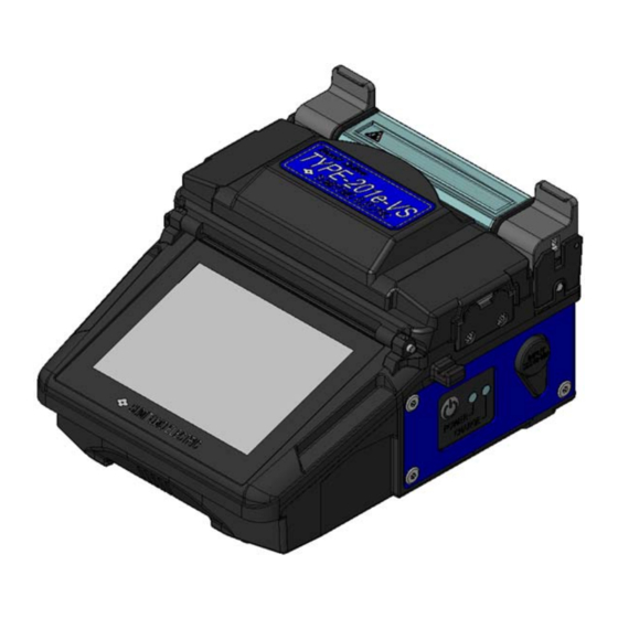
1. General Thank you very much for purchasing the TYPE-201e-VS/M4 Handheld Fusion Splicer. The TYPE-201e-VS/M4 automatically pre-inspects and aligns a pair of optical fibers with equipped microscopes, and then fuses them together with heat from an electric arc to form a low-loss splice. A protection sleeve is applied over the bare glass and cured in the built-in heat shrink oven. -
Page 17: Features Overview
Features overview The TYPE-201e key features are: ・Touch screen monitor (For more information, refer to page 2-8.) 3.5 inch LCD monitor with touch screen operation enables to confirm fiber images easily. The splicer can be operated by touching the icons on the screen. The working efficiency has improved dramatically. -
Page 18: Standard Package
Standard package Here is an example of TYPE-201e-VS/M4 standard package. Package contents (example) Description Part number TYPE-201e-VS 1 pc Fusion splicer TYPE-201e-M4 1 pc FHS-025 1 pair Fiber holders FHM-4 1 pair AC adapter ADC-1340A 1 pc Power cord PC-AC<X>*... - Page 19 Operation manual etc V-groove cleaning brush (Optional*) TYPE-201e-VS/M4 Spare electrode Cooling tray (Optional*) Fiber holder USB cable AC adapter Fiber cleaver (Optional*) Battery pack Jacket remover (Optional*) Strap for carrying case Silica gel pack Carrying case Battery charger Power cord...
-
Page 20: Optional Accessories
Optional accessories The following optional accessories are provided for the TYPE-201e. For further details, please contact our sales personnel. Part name Part No. Description <Optional accessories for main unit> BU-12S Li-ion battery for TYPE-201e Battery pack BU-12L Large capacity Li-ion battery for TYPE-201e AC adapter ADC-1340A AC adapter for TYPE-201e... -
Page 21: Consumables
Consumables Fiber protection sleeves, electrodes and battery pack are consumables. Please place an order if you need any. Part name Part No. Description Quantity For single fiber φ0.25mm~0.9mm FPS-1 50 pcs/pack Length 60mm, Cleave length ≤16mm For single fiber φ0.25mm~0.9mm FPS-40 50 pcs/pack Length 40mm, Cleave length ≤10mm... -
Page 22: Structure
Structure Fusion splicer Main body Heat shrink oven TYPE-201e fusion splicer Heat shrinks fiber protection sleeve. Switch DC-IN cover Power ON/OFF switch Cover for DC input. Touch screen monitor Input/output panel Displays fiber image, splice data and Cover for microSD card slot and USB menu. -
Page 23: V-Grooves, Electrodes, Other Components
V-grooves, electrodes, other components V-grooves Keep bare fibers aligned. (The example picture on the left shows the VS type.). Fiber holder stage A fiber holder is placed on the stage. Electrode cover plate Holds the electrode seated into the retaining groove. Electrodes Arc is generated between the electrodes. -
Page 24: Heat Shrink Oven
Heat shrink oven Heating plate Heat shrink oven lid Heats fiber protection sleeve. Closed during the heating process. Prevents the heating plate from being touched. Clamp Hold fiber coating straight. Input/output panel On right side On left side microSD card slot DC input terminal A slot for a microSD card. -
Page 25: Caution Label
Caution label High voltage High temperature heater When the arc is discharged, Heater may reach 200°C. a high voltage is generated Please take care when you use in the electrode. Please pull heater. out the power cord, and detach the battery pack when touch electrode. -
Page 26: Splice / Protection
The following is a summary of the steps required to make a splice with the fusion splicer. For further information on each step, please see the page described below. Turning on the TYPE-201e-VS/M4---Page 2-7 Initial screen---Page 2-8 Starting the automatic splice... -
Page 27: Preparing Power Supply
Preparing power supply The power for TYPE-201e-VS/M4 is supplied by AC adapter or battery. AC operation Please connect AC adapter (ADC-1340A) with TYPE-201e-VS/M4 when you operate with the AC adapter. Plugging Insert the power cord into the AC adapter completely. -
Page 28: Battery Operation
Battery operation Please install a battery pack (BU-12) in the battery pack slot of TYPE-201e-VS/M4. Turn off the splicer and disconnect the AC adapter before installing and removing the battery pack. *Please check the charge before the battery pack is installed. -
Page 29: Battery Level Check
Battery level check The battery icon in the monitor screen shows the battery level or charging status. Battery level Charging status Indicator Indicator Meaning Meaning Charging. Battery remains enough. Over 80% 61 to 80% Charging process is complete. 41 to 60% *Be sure to charge the battery pack before use when the battery level is 21 to 40%... -
Page 30: Charging The Battery Pack
Charging the battery pack 1. Install the battery pack in the splicer. 2. Connect the AC adapter to the splicer and plug it in. 3. After a few seconds, the CHARGE LED (adjacent to the POWER LED on the side of the splicer) blinks in orange and the charging process starts. 4. -
Page 31: Precautions For Battery Pack
Precautions for battery pack • Before using the battery pack for the first time, charge the battery pack. (The battery is not fully charged before shipping.) • The battery pack is a consumable. Repeated charging and discharging decreases battery life. •... -
Page 32: Operating Procedures
Operating procedures Turning on the TYPE-201e-VS/M4 1: Ensure that the electrodes are fully inserted in the splicer. 2: Insert the output cord of the AC adapter into the DC input terminal. 3: Press the power ( ) key for more than 1 second to turn on the power. -
Page 33: Initial Screen
Each motor of the splicer is initialized after turning on the power supply, and the ready DISP screen is displayed after a few seconds. TYPE-201e-VS/M4 has the touch screen function that enables to operate by the icons on the screen. Start... - Page 34 1: Clean the fiber coating thoroughly to remove cable gel or other stains. 2: Strip the fiber coating. (An example shows use of Sumitomo JR-M03 tool, strip length shown apply to any stripping tool. If you use another jacket remover, please refer to its operation manual.)
-
Page 35: Stripping The Ribbon Fiber Coating / Cleaning The Bare Fiber
Stripping the ribbon fiber coating / Cleaning the bare fiber An example shows use of Sumitomo JR-6 hot jacket remover. Please read the JR-6 operation manual before use. If you use another jacket remover, please refer to its operation manual. - Page 36 5: Ensure that the HEATER LED is lit in green and hold the JR-6, especially the “PUSH” portion of the main body lid firmly. Then slide the holder receptacle and holder lid slowly in the direction indicated by the arrow. 6: The fiber coating is removed.
-
Page 37: Cleaving The Fiber
Cleaving the fiber An example shows use of Sumitomo FC-6M fiber cleaver. Please read the FC-6M operation manual before use. If you use another fiber cleaver, please refer to its operation manual. Standard cleave length: 10mm Top clamp lever 1-1: Open the coating clamp lid and the top clamp lever. - Page 38 4-3: Lift the off-cut and dispose of it properly. *Be careful not to touch the off-cut against the fiber end face. 4-4: Place the fiber holder into the TYPE-201e-VS/M4. 4-5: Cleave the other fiber in the Off-cut same way. 1. Do not re-clean the fiber after cleaving.
-
Page 39: Inserting Fibers Into The Splicer
Inserting fibers into the splicer 1: Open the hood. 2: Place the fiber holder onto the holder stage, fitting the pin of the fiber holder stage into the hole of the fiber holder. 3: Place the other fiber holder in the same way. -
Page 40: Arc Test
If you make a splice on standard program such as “SM:1c”, perform an arc test with the fiber being spliced before fusion splicing. In the Auto mode, TYPE-201e-VS/M4 analyzes the arc and has the function to calibrate the arc condition automatically at each splice. Therefore, arc test is not needed usually in the Auto mode. - Page 41 3: Touch the “Arc test” ( 60mm 0.25 SM: 1c 4: “Arc Test Ready” screen will be displayed. MENU DISP Start Arc Test Ready 5: Touch the “Start” ( 60mm 0.25 Start SM: 1c 6: An arc test is started. Fibers are not MENU spliced because they are not moved forward during arc.
-
Page 42: Fiber Preparation
2: Strip the fiber coating and clean the bare fiber. Refer to page 2-9. 3: Cleave the bare fiber to proper cleave length. Refer to page 2-12. 4:After setting the prepared fibers on TYPE-201e-VS/M4, splicing starts by touching Start “Start” ( ). (Please refer to the next page.) -
Page 43: Starting The Automatic Splice
Starting the automatic splice 60mm 0.25 SM: 1c See the next page if you skip MENU the checking of splice data and go on to the next step. DISP Checking splice data • After a splice, touch the “Data” ( DATA Start Ready... - Page 44 See the next page if you skip the checking of splice image and go on to the next step. Checking splice image 60mm 0.25 60mm 0.25 SM: 1c SM: 1c MENU MENU 1 0.00 dB 1 0.00 dB DISP DISP DATA DATA Tool...
- Page 45 Proof test (if manual proof test is selected) 60mm 0.25 60mm 0.25 SM: 1c SM: 1c MENU MENU 1 0.00 dB 1 0.00 dB DISP DISP DATA DATA Tool Tool Reset Reset Estimation Loss Estimation Loss Estimation Loss Estimation Loss Estimation Loss Open the hood.
- Page 46 Evaluating splice quality If the spliced fiber is as follows or estimated losses are high, re-do the entire splice. 60mm 0.25 SM: 1c MENU 1 0.00 dB DISP DATA White line Tool (Re-arc→NG→ Re-do splicing) Reset Estimation Loss Estimation Loss Bulging Neck-down Bubble...
-
Page 47: Splice Protection
Splice protection 1: Open the heat shrink oven lid and the heat shrink oven clamps. Open the hood and the fiber coating clamps to release the spliced fiber. 2: Make sure that the fiber protection sleeve is centered over the spliced portion of the fiber. - Page 48 6: The splicer gives a beep sound indicating completion of the heating cycle. Take out the sleeve from the heat shrink oven after a beep sound is heard. 7: Place the protection sleeve onto the cooling tray. The protection sleeve can be taken out from the heat shrink oven after a beep sound is heard.
-
Page 49: Drop Cable Splicing
Drop cable splicing Removing cable sheath The TYPE-201e-VS/M4 can achieve splicing of drop/small-sized indoor cable fiber. This section outlines procedures on how to remove cable sheath. Clean the cable sheath thoroughly to remove cable gel or other stains. 1. Separate the steel wire from the 2. -
Page 50: Fiber Preparation Procedures
Fiber preparation procedures 2. Remove the fiber coating at 1. Load the cable with its sheath 2~4mm away from the edge of removed in the fiber holder. the fiber holder. (Touch the Make sure that the cable sheath JR-M03 against the edge to touches the groove. - Page 51 Inserting the fiber into the splicer 1. Open the hood. 2. Place the fiber holder onto the fiber holder stage, fitting the pin of the stage into the hole of the fiber holder. Take great care not to touch the fiber end face against any surfaces.
-
Page 52: Splice Protection
Splice protection 1. Open the oven lid and oven clamps. Open the hood and all lids of the fiber holders. 2. Take out the cable and slide the fiber protection sleeve onto the fiber. Make sure that the protection sleeve is centered over the splice and at least 5mm of the sleeve overlaps the cable sheath at each end of the splice. -
Page 53: Daily Cleaning And Checking Up
Especially cleaning should be performed before and after each use. We recommend your splicer to be checked through our maintenance service once a year. Turn off the TYPE-201e-VS/M4 before maintenance work. Failure to do so may cause electric shock. Warning Cleaning Clean each part with a cotton swab. -
Page 54: Cleaning V-Grooves
Cleaning V-grooves Even tiny bits of dust or dirt in the V-grooves might cause the fiber to be offset. To avoid offset, carefully clean the V-grooves with a cotton swab moistened with alcohol. Prepare V-groove cleaning brush or cotton swab moistened with alcohol. -
Page 55: Cleaning Microscope Objective Lens
1: Prepare a cotton swab moistened with alcohol and wipe the surface of LED 2: Use a dry cotton swab to wipe off any excess alcohol. Do not use a canned air for cleaning. Prohibition Chemical reaction may deteriorate the LED, resulting in a loss of splicing capability. -
Page 56: Cleaning Heat Shrink Oven
Do not use a canned air for cleaning. An electrode tip is extremely sharp. Chemical reaction may deteriorate the Handle with care. Caution Prohibition lens protection glass, resulting in a loss of splicing Cleaning heat shrink oven Dirt and dust can accumulate in the heat shrink oven easily. Clean the heating plate regularly with a dry cotton swab. -
Page 57: Replacing Electrodes
Replacing electrodes Electrodes are worn out or contaminated due to silica glass evaporated during arc, and the electrode condition changes day by day. To achieve a repetitive and stable arc for excellent quality splicing, electrodes should be replaced periodically. Continuing to use the same electrodes may result in high splice losses and poor splice strength. -
Page 58: Electrode Replacement Procedures
Electrode replacement procedures To keep the excellent performance of the TYPE-201e-VS/M4, replace electrodes with new ones after 1,500 arc discharges for theTYPE-201e-M4, and after 3,000 arc discharges for the TYPE-201e-VS. The tip of an electrode is extremely sharp. Handle with care... - Page 59 Caution Make sure the plastic button of the electrode is certainly pushed against the protrusion. Plastic button Protrusion <OK> <NG> Splice performance will unstable or a part of the splicer Caution is damaged if electrodes are not installed in place correctly An electrode tip is extremely sharp.
-
Page 60: Packing And Storage Instructions
• Store the TYPE-201e-VS/M4 in the direction shown in the photo below. • The TYPE-201e-VS/M4 with a cooling tray cannot be stored in the case. Remove the cooling tray from the splicer and store it in the pocket. - Page 61 Observe the following instructions. • Clean the TYPE-201e-VS/M4 and all accessories before storing them. • Be sure to remove the battery pack from the TYPE-201e-VS/M4 and store it in a given place. Keeping the battery in the TYPE-201e-VS/M4 may cause the...
-
Page 62: Functions
4. Functions Splice and heater programs setting <Splice program setting> *The example below shows use of TYPE-201e-M4. 60mm 0.25 60mm 0.25 SM: 1c MM: 4c MENU MENU DISP Start Reset Ready Prefusion check Ready Splice program is changed. Touch the splice program icon once. - Page 63 <Heater program setting> Heater Program 40mm 1-8c STD SM: 1c 60mm 0.25 MENU FPS-1 40mm 0.25 DISP FPS-40 40mm 1-8c STD FPS-5 40mm 12c STD FPS-6 Start Ready Ready Select Heater Program If the page icon ( ) displays the Touch the heater program icon once.
- Page 64 Splice programs Details Category Splice Program SM : Auto Used to splice identical standard SMF (ITU-T G.652). MM : Auto Used to splice identical standard MMF (ITU-T G.651). Auto Used to splice identical standard DSF (ITU-T G.653), DS/NZ: Auto ...
- Page 65 Heater programs Heater programs are optimized for Sumitomo protection sleeves. Select an appropriate heater program for the protection sleeve you use. Heater program Details Used to heat shrink standard 60mm protection sleeves 60mm 0.25 FPS-1 for 0.25mm coated single fiber. Best suitable program for Sumitomo FPS-1.
- Page 66 Can be used for heat shrinking 40mm protection 40mm 0.4 FPS-N4-40 sleeves of Nano Sleeves N4 series, for example, Sumitomo FPS-N4-40. Can be used for heat shrinking 25mm protection 25mm 0.4 FPS-N4-25 sleeves of Nano Sleeves N4 series, for example, ...
- Page 67 <Change splice program parameter> <Change heater program parameter> *The example below shows use of TYPE-201e-M4. Splice Program Heater Program 60mm 0.25 SM: 1c FPS-1 40mm 0.25 SM: 2c FPS-40 40mm 1-8c STD SM: 4c FPS-5 40mm 12c STD FPS-6 Select Heater Program Select Splice Program Splice Program Select Heater Program...
- Page 68 Splice program items Page <Fusion Time> Fusion time is the duration of arc discharge. (Numerical input) <Prefusion Time> Pre-fusion time is the time in seconds the fiber ends wait after the arc discharge begins before beginning the overlap (feed). (Numerical input) <Arc Gap>...
-
Page 69: Function Settings
Function settings 60mm 0.25 SM: 1c MENU DISP Start Ready Ready Touch “Menu” ( ) to go to MENU menu screen. Menu DATA Function Splice Maintenance Security Data Login Information For more details of the items of function, please refer to the page 4-9. 01/01/2014 12:00 Select Item Select Item... - Page 70 Functions Page <Arc Pause> This function stops the splicing process before arcing occurs. If you would like to check offset and fiber end faces, set this function to ON. <Sleep> If the splicer is not interrupted for a certain span of time, to minimize power consumption on standby, the monitor and 12VDC will be turned off.
-
Page 71: Maintenance Settings
Maintenance settings Maintenance 60mm 0.25 SM: 1c Conditioning Arc MENU Reset Arc Count DISP Bright Arc Count 0046 All Count 000104 Turn power off and Take power unit out of splicer Start when electrodes changed Ready Ready Touch the item once. The icon will be Touch “MENU”... -
Page 72: Splice Data Storage Function
Splice data storage function Touch the “Splice Data” icon ( ) on the Splice Data DATA menu screen to go to DATA screen. Please set Memory "Memory" to ON before splicing if you want to save splice data. Display SMF Quick [0003] Copy SMF Quick... -
Page 73: Usb Connection Function
) in the menu screen USB Mode to go to the USB mode screen. The following functions can be used by connecting the removable disk TYPE-201e-VS/M4 to a PC via USB cable, and SMF Quick Remote Diagnosis selecting each item. <Removable disk>:... -
Page 74: Help Function
Help function The TYPE-201e-VS/M4 has a function to show user training videos as to fiber preparation, daily maintenance and cleaning. It is possible to play back and pause, which enables an operator to go over operating procedures. Information Menu Help Video... -
Page 75: Troubleshooting
5. Troubleshooting For repair and technical support, contact maintenance service center address described in the back cover. Arc problems Electrodes typically need replacing after 1,500 splices for TYPE-201e-M4, 3,000 splices for TYPE-201e-VS. Some common symptoms that indicate the electrodes need replacing are: ٠High or inconsistent splice losses ٠Bubbles in the fibers after splicing... -
Page 76: Warranty And Repair Service
(7) Damage or malfunction caused by use of batteries and battery chargers not specified or approved by Sumitomo. (8) Products founds corroded due to exposure to water or dew condensation, or cracked or deformed circuit board. 3. The customer shall bear the cost of returning the product to Sumitomo. -
Page 77: Error Message List
Error message list Please contact maintenance service center when it is not recovered if you take the measures below. Error message Countermeasure The fibers are not placed correctly into the Place the fiber correctly into the V-groove again. V-groove. >Refer to page 2-14. There is a possibility that dust or dirt is on the V-groove and the fiber clamp when the error occurs repeatedly. -
Page 78: Type-201E-Vs/M4 Specifications
[TYPE-201e-VS/M4 specifications] Item Material Silica glass SMF (ITU-T G.652), MMF (ITU-T G.651) Profile types DSF (ITU-T G.653), NZDSF (ITU-T G.655) BIF (ITU-T G.657) Drop cable (2.0mm×3.1 or 2.6mm) Cable types Indoor cable (2.0mm×1.6mm) Optical fiber Fiber diameter 125µm requirement Single fiber coating dia: 250μm, 500μm, 900μm... - Page 79 *11 Dust resistance: Operates normally after 8 hours in a dust chamber containing dust of particle size 75μm or below. The test is held with the battery operation, carried out by Sumitomo, but does not guarantee that the product is free of faults or damage.
- Page 80 Elstree, Herts, WD6 3SL, U.K. Tel: +44 (0)20 8953 8118 Bangkok (Thailand) Manila (Philippines) http://www.sumielectric.com/ Sumitomo Electric (Thailand) Limited SEI (PHILIPPINES) INCORPORATED Tel: +66 (0)2 260 7231 to 5 Tel: +63 2 811 2755 to 2756 http://www.set-th.com/ ©2014 SUMITOMO ELECTRIC INDUSTRIES, LTD.
Need help?
Do you have a question about the TYPE-201e-VS/M4 and is the answer not in the manual?
Questions and answers