
Related Manuals for Sumitomo 82C+


Summary of Contents for Sumitomo 82C+
- Page 1 TYPE-82C + Guide to operation Be sure to read all the following warnings and cautions before use.
- Page 2 IMPORTANT SAFTY PRECAUTIONS This product has been designed and manufactured to assure personal safety. Improper use can result in fire, electric shock or injury to persons. Please read and observe all warnings instructions given in this operation manual. Use your splicer only for its intended purpose. ♦...
- Page 3 3. Do not use and store the splicer out of the locations defined in a brochure and this manual. Doing so can cause splicer malfunction or deterioration, resulting in fire or electric shock. 4. To reduce the risk of fire, electric shock or malfunction, do not allow the splicer to be exposed to rain and get liquid such as water or a metallic object inside the splicer.
- Page 4 26. Be sure to turn off the splicer and unplug the power cord or remove the battery pack before replacing the electrodes. 27. Only use Sumitomo genuine electrodes (ER-10). And use the splicer with electrodes installed in it. Failure to do so can cause the splicer to damage, resulting in fire, electric shock or malfunction.
- Page 5 <Handling of battery pack> 1. Do not burn the battery pack or throw it into a fire. Doing so can cause heat generation, bursting and fire. 2. Do not place the battery pack in microwave ovens and high-pressure containers. 3. Do not let water or sea water wet or soak the battery pack. Safety and protective devices to prevent danger are built in the battery pack.
- Page 6 [Caution] <Transportation and storage> 1. This product is a precision instrument. When transporting the splicer, use its specified carrying case to protect the splicer from excessive shock or impact. 2. Do not use and store the splicer out of the locations defined in a brochure and this manual.
- Page 7 <Battery handling and charging> 1. Make sure the polarities are correctly connected. Do not attempt to connect the battery pack or other equipment when you cannot do. Reversed connections can cause abnormal chemical reaction in battery fluid, heat generation, bursting and fire. 2.
- Page 8 20. Be sure to remove moisture, alcohol or dust on the heater element with a dry cotton swab. 21. Only use Sumitomo genuine electrodes (ER-10). Failure to do so can cause the splicer to malfunction. 22. Do not clean the electrode. Doing so can cause unstable arcing performance.
-
Page 9: Important: Region Limitation
Sumitomo Electric Industries, LTD. YOU NEED TO AGREE ABOUT A SOFTWARE LICENCE AND REGION LIMITATION BEFORE USE. Reference of Sales Area and Sumitomo Sales & Service Representatives: Sales Area Sumitomo Sales and Service Representatives North America, CALA Sumitomo Electric Lightwave Corp. -
Page 10: Important: Patent Notice
IMPORTANT: PATENT NOTICE This product and/or the use of this product are/is covered by one or more of the following Patents of Sumitomo Electric Industries, LTD.: 2002222577; 2006235914 Australia Patent No(s).: 2431138; 2560225; 2592772; 2804689; Canada Patent No(s).: 2814387; 2823147 133128;... -
Page 11: Important: Type-82C+ Software User License
Copyright © 2020 SUMITOMO ELECTRIC INDUSTRIES, LTD. All rights reserved. ATTENTION : The software installed in the TYPE-82C+ SPLICER (“this software”) is the property of SUMITOMO ELECTRIC INDUSTRIES, LTD. The usage of this software is granted by a license. CAREFULLY READ AND THIS LICENSE BEFORE USING THIS PRODUCT. - Page 12 SD logo is a trademark or registered trademark of SD-3C LLC. Apple is a trademark or registered trademark of Apple Inc. Google play is a trademark or registered trademark of GOOGLE LLC. IMPORTANT:TYPE-82C+ SOFTWARE USER LICENCE...
-
Page 13: Table Of Contents
Table of contents IMPORTANT SAFETY PRECAUTIONS IMPORTANT: REGION LIMITATION IMPORTANT: PATENT NOTICE IMPORTANT: TYPE-82C+ SOFTWARE USER LICENSE 1.Introduction Product overview ❚ ● Optical fiber requirement ● Features overview ● Standard package Related products ❚ ❚ Structure ❚ Screens and icons 1-11 ●... - Page 14 Splicer is not turned on ❚ Error message list ❚ Warranty and repair service ■Sumitomo Electric industries, Ltd. reserves the right to change the specification or design without notice and may therefore not coincide with the contents of the manual. E&OE Table of contents...
-
Page 15: 1.Introduction
1.Introduction ❚ Product overview The TYPE-82C+ automatically pre- inspects and aligns a pair of optical single fibers with equipped microscopes, and then fuses them together with heat from an electric arc to form a low-loss splice. A protection sleeve is applied over the bare glass and cured in the built-in heat shrink oven. -
Page 16: Features Overview
1.Introduction ● Features overview The TYPE-82C+ key features are: NanoTune™ Technology The NanoTune™ analyzes a fiber end face and automatically fine-tunes splice condition to achieve an ideal splice. Coping with poorly cleaved optical fiber, which cannot be spliced by conventional splicers, the NanoTune™ can yield the best quality and low loss splices. -
Page 17: Standard Package
1.Introduction Standard package ● Here is an example of TYPE-82C+ standard package. Package contents (example) Description Part number Quantity Fusion splicer TYPE-82C+ 1 pc Carrying case CC-82 1 pc Battery pack BU-16 1 pc AC adapter ADC-16 1 pc Power cord PC-AC<X>* 1 pc Spare electrodes... -
Page 18: Related Products
1.Introduction Related products ● To place an order for tools, consumables, and optional accessories, please contact our sales personnel. ■ Optional accessories Part name Part No. Description <Optional accessories for main unit> Battery pack BU-16 Li-ion battery for TYPE-82C+ Plugged into a car’s cigarette light jack to supply Car battery cable PCV-16 power to splicer... -
Page 19: Structure
1.Introduction ❚ Structure Heat shrink oven Hood Keypad Input/output panel Touchscreen monitor Battery pack slot Heat shrink oven Keypad Used to heat and shrink fiber Keys are used to turn on/off the protection sleeves. The splicer power, perform a splice and heat has 2 independent heat shrink shrink protection, and set up functions. - Page 20 1.Introduction ■Keypad Keys are equipped on the top of the splicer. There are also SET, RESET and HEAT icons on the touchscreen monitor. HEATER Key 2 HEATER Key 1 POWER key HEATER key2/ LED Turns on and off the splicer. LED Starts/cancels the heating illuminates while the splicer is cycle of the rear heat shrink...
- Page 21 1.Introduction ■V-grooves, electrodes, other components V-groove illumination Illuminates the V-groove. Lit when the hood is opened. Electrode cover plate Holds the electrode seated into the retaining groove. Electrodes Arc is generated between the electrodes. V-grooves Keep bare fibers aligned. Lens protection glass Protects the lens surface.
- Page 22 1.Introduction ■Input/output panel USB port SD card slot SELECT switch DC input terminal DC output terminal USB port DC input terminal Used to download stored splice Input power via AC adapter. loss data when connected to a SD card slot DC output terminal For splice data output.
- Page 23 1.Introduction SELECT switch feature The SELECT switch helps you select splice and heater programs when the touchscreen does not work. Follow the procedures below. 1) Turn the power OFF. (if the splicer is powered on.) 2-A) If you have not set a start-up password, turn the power ON while keep hold- ing down the SELECT switch until "Splice Program"...
- Page 24 1.Introduction ■Caution label 1 Installing electrode High voltage 2 3 High temperature heater 4 High temperature heater 5 Prohibition of using spray Installing electrode High temperature heater 3 1 Before splicing make sure the The Heater reaches approx. electrode is installed in the 200°C.
-
Page 25: Screens And Icons
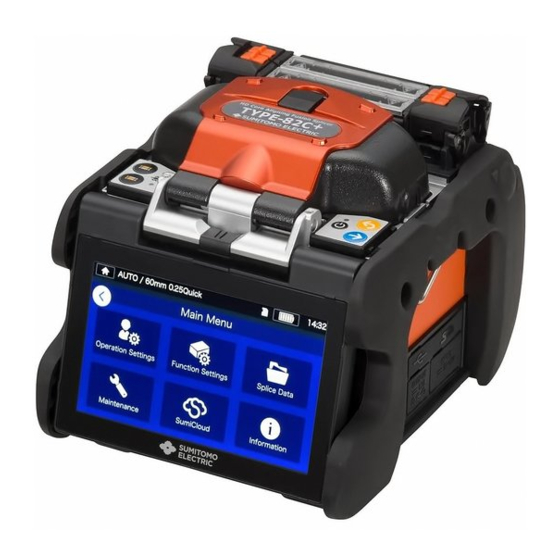
1.Introduction ❚ Screens and icons ● Home screen After the splicer is turned on, Home screen is displayed. Splice program Heater program SD Power Time Heater progress bar Heater 2 Heater 1 Heater 2 Heater 1 Heater panel Control panel Settings panel icon: Display the Settings panel. -
Page 26: Settings Panel
1.Introduction Settings panel ● To display the Settings panel, tap the Settings panel icon on the Home screen. Display the Menu screen. You can edit settings. ▸For more details, see Chapter 6 Set up splice program. ▸P.2-9: Selecting splice program, Chapter 4: Splice program Set up heater program. -
Page 27: Basic Splicing Operation
2. Basic splicing operation This chapter describes basic fiber splicing operation using fusion splicer. ❚ Preparation for splicing Before splicing, get all the necessary items ready. TYPE-82C+ standard package ・Jacket remover ・Fiber cleaver ・Fiber protection sleeves* ・Pure (more than 99%) alcohol ・Lint-free gauze wipes TYPE-82C+ standard package Jacket remover... -
Page 28: Splicer Operating Procedures
2. Basic splicing operation ❚ Splicer operating procedures The following is a summary of the steps required to make a splice with the fusion splicer. For further information on each step, please see the page described below. P.2-8 Turning on the TYPE-82C+ Home screen P.2-8 Selecting s plice program... -
Page 29: Preparing Power Supply
2. Basic splicing operation ❚ Preparing power supply The TYPE-82C+ is powered from AC adapter or battery. ● AC operation Connect the AC adapter (ADC-16) to the TYPE-82C+ when you operate the splicer on AC power. Plugging Insert the power cord into the AC adapter completely. -
Page 30: Battery Operation
2. Basic splicing operation ● Battery operation Install the battery pack (BU-16) into the slot of the TYPE-82C+ as described below. Turn off the splicer and disconnect the AC adapter from the splicer before installing and removing the battery pack. ▸P.2-5 “Battery charging”... - Page 31 2. Basic splicing operation ■ Battery charging • Before using the battery pack for the first time, charge the battery pack. (The battery is not fully charged before shipping.) 1: Insert the battery pack into the TYPE-82C+. 2: Connect the AC adapter to the TYPE-82C+. 3:...
- Page 32 2. Basic splicing operation ■ Battery level check ・Check the battery level on the battery pack Press the battery check button. The LED will light up for a few seconds to indicate the battery status in one of five levels. Battery check button 61 〜...
-
Page 33: Dc Operation(Car Battery)
2. Basic splicing operation Precautions for battery pack • The battery pack is consumables. Repeated charging and discharging decreases battery life. • Store the battery pack within the following temperature range. Failure to do so may lead to deterioration in performance. *Battery pack storage temperature range: -20°C ~ +50°C (if stored for less than 1 month) -20°C ~ +40°C (if stored for less than 3 months) -
Page 34: Optical Fiber Splicing
2. Basic splicing operation ❚ Optical fiber splicing Turning on/off the splicer ● ■Turning on the splicer 1: Ensure that the electrodes are fully inserted in the splicer. 2: Insert the output cord of the AC adapter into the DC input terminal. 3: Adjust the monitor angle to your own preference. -
Page 35: Selecting Splice Program
2. Basic splicing operation Selecting splice program ● 4: Splice program is changed. 1: Tap the Splice program label on the Settings panel. Splice Program screen 2: Select a fiber category. ▸ P.4-1, P.4-2 Splice program list ▸ P.4-3 Customizing splice program 3: Tap the splice program you would like to use. -
Page 36: Selecting Heater Program
2. Basic splicing operation ● Selecting heater program 1: Tap the Heater program 4: Heater program is changed. label on the Settings panel. Heater Program screen 2: Select a sleeve type. ▸ P.5-1, P.5-2 Heater program list ▸ P.5-3 Customizing heater program 3: Tap the heater program you would like to use. -
Page 37: Stripping The Fiber Coating / Cleaning The Bare Fiber
2: Strip Approx. 30~40mm of the fiber coating with a jacket remover. (An example shows use of Sumitomo JR-M03 jacket remover and the strip length shown below applies to any stripping tools. If you use other model, please refer to its operation manual.) -
Page 38: Cleaving The Fiber
2. Basic splicing operation Cleaving the fiber ● Cleave the fiber. (An example shows use of Sumitomo FC-6S fiber cleaver, the cleave length shown applies to any cleaving tools. If you use other model, please refer to its operation manual.) Applicable cleave length: 5mm-20mm (φ0.25mm), 10-20mm (φ0.9mm) - Page 39 2. Basic splicing operation 5: Open the top clamp lever. Bare fiber Then open the lid of the single fiber adapter and lift the newly cleaved fiber. Lift the off-cut Cleave and dispose it properly. Fiber coating length 1: Do not re-clean the fiber after cleaving. 2: To avoid damaging or contaminating a delicate fiber end, insert the fiber in the splicer immediately after preparation.
-
Page 40: Inserting Fibers Into The Splicer
2. Basic splicing operation Inserting fibers into the splicer ● 1: Open the hood and the fiber coating clamp lid. 2: Place the fiber in the splicer so the fiber end is between the edge of V-groove the v-groove and the electrodes. Electrode Fiber 3: Close the fiber coating clamp lid. -
Page 41: Arc Test
2. Basic splicing operation Arc test ● The fusion splicing is a method of melting and connecting the point of optical fiber by heat of electrical discharge. Since optimum arc conditions are different depending on the environments (atmospheric pressure and temperature) and the electrode conditions (wear-out and accumulation of the glass) and the optical fibers (manufacturer and SMF/MMF, etc.), an optimum arc condition is essential to achieve a low splice loss. - Page 42 2. Basic splicing operation ■Arc test procedure 4: The melt back distance of the left and 1: As mentioned in the previous right fibers and the arc center position pages, load a prepared fiber. (The which measured image coating is removed and fiber is processing are displayed on the monitor cleaved.) screen.
-
Page 43: Starting The Automatic Splice
2. Basic splicing operation ● Starting the automatic splice Here is a summary of the splicing operation procedures. 1: Slip a protection sleeve over the fiber. Be sure to slip the fiber protec- tion sleeve over one of the fibers 2: Strip the fiber coating and clean the to be spliced before stripping and cleaving the fibers. - Page 44 2. Basic splicing operation Checking splice image and data ■ You can check and save image and/or text splice data at the arc pause stage or after splicing. Tap the Control panel icon ( ). You can do the following actions. View splice data after splicing Adjust the zoom of a fiber image.
- Page 45 2. Basic splicing operation ■ Splice error possible cause and troubleshooting Do a visual check of the splice point viewed on the monitor. If any symptoms below appear or an estimated loss is too high, read the troubleshooting against the symptom and re-do the entire splicing procedures from the beginning.
-
Page 46: Proof Test
2. Basic splicing operation Proof test ● After fusion splicing is complete, the splicer performs a proof test to verify the tensile strength of the splice. Open the hood or tap the Set icon to start the proof test. (Once started, the proof test cannot be cancelled.) Automatic proof test Manual proof test... -
Page 47: Splice Protection
2. Basic splicing operation ● Splice protection 1: Open the heat shrink oven lid and the heat shrink oven clamps. (▸P.7-5 Heater clamp operation) 2: Open the hood and the fiber coating clamps. Take spliced fiber. Do not flex and bend Slide the protection sleeve (▸P.2- ) over the center of the splice. - Page 48 2. Basic splicing operation Heater progress bar 5: The Heater progress bar shows a progress of the heating cycle. The splicer gives beep sound indicating completion Standby heating cycle. Take out the sleeve from the heat shrink oven after a beep sound is heard.
-
Page 49: Drop Cable Splicing
2. Basic splicing operation ❚ Drop cable splicing Applicable cable ● ▪ Tight buffer type single fiber drop cable. Required items ● ▪ Fusion splicer (TYPE-82C+) ▪ Allen key 1.5mm ▪ Cross-recessed screwdriver ▪ Nippers ▪ Jacket remover ▪ Fiber cleaver ▪... -
Page 50: Removing Cable Sheath
2. Basic splicing operation ● Removing cable sheath Clean the cable sheath thoroughly to remove cable gel or other stains. 1: Separate the steel wire from the 4: Make a slit along the groove of the cable using nippers. cable sheath using nippers. 5: Split the cable sheath to expose 2: Cut the steel wire to a desired 30~40mm of optical fiber. - Page 51 2. Basic splicing operation ● Fiber preparation procedures 1 (AP-FC6SA is available) This section outlines fiber preparation procedures in using a fiber cleaver with a single fiber adapter (AP-FC6SA). If your fiber cleaver does not have the single fiber adapter or a single fiber adapter attached to your cleaver is AP-FC6M, please refer to the procedures 2.
- Page 52 2. Basic splicing operation Fiber preparation procedures 2 (AP-FC6SA is not available) ● This section outlines fiber preparation procedures in using a fiber cleaver without single fiber adapter (AP-FC6SA). If AP-FC6SA is available, please refer to the procedures 1. 1: Load the cable with its sheath 3: Clean the bare fiber from the end of removed in the fiber holder.
-
Page 53: Inserting The Fiber Into The Splicer
2. Basic splicing operation ● Inserting the fiber into the splicer 1: Open the hood. 4: Close the hood. 2: Place the fiber holder onto the fiber 5: Start the splicing process. holder stage, fitting the pin of the stage into the hole of the fiber holder. ▸... -
Page 54: Splice Protection
2. Basic splicing operation Splice protection ● 1: Make the left hand oven clamp linked with the oven lid and the right hand oven clamp independent. Open the oven lid and oven clamps. Open the hood and all lids of the fiber holders. -
Page 55: Maintenance
3. Maintenance To keep excellent splice quality, regular cleaning and inspection are required. Especially cleaning should be performed before and after each use. We recommend your splicer to be checked through our maintenance service periodically. ❚ Cleaning Turn off the TYPE-82C+ before maintenance work. Clean each part with a cotton swab. -
Page 56: Cleaning Leds And Bare Fiber Pads
3. Maintenance ● Cleaning LEDs and bare fiber pads ● <Inside of hood> Bare fiber pad ■ Cleaning bare fiber pads Dirt on a bare fiber pad will cause the fiber to be offset. When fiber offset occurs, clean the bare fiber pad. 1: Prepare a cotton swab moistened with alcohol and wipe the surface of bare fiber pads. -
Page 57: Cleaning Lens Protection Glass
3. Maintenance Cleaning lens protection glass ● ● If an unclear fiber image is still displayed or LED error occurs again after cleaning LEDs, clean the lens protection glass. Lens protection glass 1: Remove the electrodes, referring to “Electrode replacement procedures”. -
Page 58: Cleaning Heat Shrink Oven
3. Maintenance Cleaning heat shrink oven ● ● Dirt and dust can accumulate in the heat shrink oven easily. Clean the heating plate regularly with a dry cotton swab. 1: Clean the heating plate with a dry cotton swab. 2 : Clean the clamps of the heat shrink oven with a cotton swab moistened with alcohol. -
Page 59: Electrode Replacement
Always replace with Sumitomo genuine electrodes in pairs at a time. Failure to do so can keep the splicer from maximizing its ability. -
Page 60: Electrode Replacement Procedures
3. Maintenance ● Electrode replacement procedures ● 1: Disconnect the power cord or remove the battery from the splicer if installed. Failure to do so can cause electric shock. Using your fingers, loosen thumbscrew. Electrode cover thumbscrew 3: Take out the electrode and electrode cover from the splicer. - Page 61 3. Maintenance Splice performance is not stable or the splicer partly gets damaged if the electrodes are installed in a wrong way. Make sure…. ・The protrusion of the electrode cover fits in the splicer properly. ・The tips of the electrodes face each other at the same height. ・The thumbscrew of the electrode cover is tightened completely.
-
Page 62: Packing And Storage Instructions
3. Maintenance ❚ Packing and storage instructions The TYPE-82C+ fusion splicer is a precision instrument. Its rugged shipping case is custom designed to protect it from impact, dust, dirt, and moisture. Always store and transport the machine in its case. •... -
Page 63: Software Update Via Internet
If you obtain maintenance application via the URL below, you can update splicer software via internet. For further information, please access the URL below and refer to a dedicated manual. https://global-sei.com/sumitomo-electric-splicers/support/firmware_update/ ・ Software update The splicer software can be updated via internet ・... -
Page 64: Splice Program
4. Splice program ❚ Splice program list The product has splice programs pre-installed as a template. The programs are optimized according to the optical fiber profiles. (▸P.2-9 Selecting splice program) AUTO Mode Splice program Details Splicing can be performed by using not only the existing AUTO mode function but the new NanoTune™... - Page 65 4. Splice program Standard Mode Perform an arc test before splicing in standard mode splice programs. (▸P.2-15 Arc test) Category Splice program Details SM G652 Std. Can be used to splice identical standard SMF (ITU-T G.652). Can be used to splice identical standard SMF (ITU-T G.652) and make a SM G652 Quick faster splice.
-
Page 66: Customizing Splice Program
4. Splice program ❚ Customizing splice program Splice program can be customized as per your requirement by editing parameters set in the program. 1: On the “Splice Program screen” 4: Select the item you would like ( ▸ P.2-9), select fiber to edit. -
Page 67: Copying Splice Program(In Administrator Mode)
4. Splice program ❚ Copying splice program (in Administrator mode) In Administrator mode, you can create your own new splice program by copying an existing splice program to a blank area of splice programs. After the copy, you can edit the name of the copied program and change the parameter settings. First, log in to Administrator mode to do this action. -
Page 68: Showing /Hiding Splice Program (In Administrator Mode)
4. Splice program ❚ Showing /Hiding splice program (in Administrator mode) An administrator can show or hide splice programs in the Operator mode. First, log in to Administrator mode to do this action. (▸P.8-1 Logging in to and logging out of Administrator mode) 1: Referring to the procedures in 3: After is selected, the... -
Page 69: Splice Program Editable Items
4. Splice program ❚ Splice program editable items 1/2 Operator Administrator Editable items Details View Edit View Edit ✔ ✔ ✔ Name Allows to edit splice program name Allows to edit heater program name which ✔ ✔ ✔ ✔ Abbreviated name is displayed on the main splice screen. - Page 70 4. Splice program ❚ Splice program editable items 2/2 Operator Administrator Editable items Details View Edit View Edit Align method Sets fiber alignment method. Choose from “Core”, “Diameter” and “Adaptive”. “Core”…Aligns the center of the cores of right and left optical fibers. ✔...
- Page 71 4. Splice program <Arc discharging and motor driving systems during the splicing process> (1) Arc time (2) Prefuse time (3) Over Lap (4) Arc Power (5) Cleaning Arc Time (6) Rearc time (7) Fiber Pulling Start (8) Fiber Pulling Length *(6) (7) (8) can only be edited in Administrator mode.
-
Page 72: Nanotune™ Splice Mode
4. Splice program ❚ NanoTune™ splice mode The NanoTune™ analyzes a fiber end face and automatically fine-tunes splice program to achieve an ideal splice. When the NanoTune™ is activated, a dedicated splice screen appears. Coping with poorly cleaved optical fiber, which cannot be spliced by conventional splicers, the NanoTune™... -
Page 73: Attenuation Splice Mode
4. Splice program ❚ Attenuation splice mode Attenuation splice mode creates an intentional core axial offset and splices fibers. 3: Select “Target Loss” or “Fiber 1: Tap the Splice program label Core Offset for ATTN” to edit once. Select the category of the value. - Page 74 4. Splice program 5: Select “ATTN Coef.” 7: Tap Set icon ( ) icon to to edit perform a splice. the value. Check an actual splice loss. If the actual splice loss still does not match the target splice loss, go back to step 5~6 to adjust ATTN Coef again.
-
Page 75: Heater Program
0.25mm coating, for example, Sumitomo FPS-1. Can be used for heat shrinking 60mm protection sleeves for single fiber with 0.25mm coating, for example, Sumitomo FPS-1. Select 60mm 0.25 Quick the program if you would like to reduce the heating cycle time. On... - Page 76 5. Heater program ❚ Heater program list The heating programs are optimized for Sumitomo protection sleeves. Select an appropriate heater program for the protection sleeve you are using. Category Heater program Details Can be used for heat shrinking 60mm protection sleeves for drop 60mmDrop cable splice, for example, Sumitomo FPS-D60.
-
Page 77: Customizing Heater Program
5. Heater program ❚ Customizing heater program Heater program can be customized as per your requirement by editing parameters set in the program. 4: Select the parameter you “Heater Program would like to edit. screen” (▸P.2-10), Select the sleeve type where you would like to change the settings. -
Page 78: Copying Heater Program(In Administrator Mode)
5. Heater program ❚ Copying heater program (in Administrator mode) In Administrator mode, you can create your own new heater program by copying an existing heater program to a blank area of heater programs. After the copy, you can edit the name of the copied program and change the parameter settings. First, log in to Administrator mode to do this action. -
Page 79: Showing/Hiding Heater Program (In Administrator Mode)
5. Heater program ❚ Showing/Hiding heater program (in Administrator mode) An administrator can show or hide heater programs in the Operator mode. First, log in to Administrator mode to do this action. (▸P.8-1 Logging in to and logging out of Administrator mode) 1: Referring to the procedures in 3: After is selected, the... -
Page 80: Heater Program Editable Items
5. Heater program ❚ Heater program editable items Operator Administrator Editable items Details Edit Edit View View Name Allows to edit the name of Heater program. ✔ ✔ Abbreviated name Allows to edit the name of Heater program ✔ ✔ ✔... -
Page 81: Functions
6. Functions ❚ Menu screen From Menu screen, you can access menu options to edit the settings. For more details, see the next pages. Home screen Settings panel Menu screen Operation Settings︓Edit the splicer operation settings such as auto start, re-arc, etc ..▸P.6-2 Function Settings: ▸P.6-5... -
Page 82: Operation Settings
6. Functions ❚ Operation Settings ■ Edit Operation Settings 1: Tap the Settings panel icon ) to open the Settings panel. 4: Tap to toggle an item ON or OFF as desired. 2: Tap the Menu label ( to display the Menu screen. Scroll down the screen to view all the items. - Page 83 6. Functions ■ Operation Settings details Editable items Details View Edit View Edit Stops the splicing process temporarily before Arc Pause arcing. If you would like to check fiber offset ✔ ✔ ✔ ✔ and fiber end faces during the process, set this function to ON.
- Page 84 6. Functions ■ Splicing process screen setup(Available in Administrator mode) Log in to Administrator mode. From the Operation Settings, you can choose a view of the fibers for the 5 stages of the splicing process. ・Fiber Insertion Screen ・Pre-Fusion Screen ・Arc Screen ・Post-Fusion Screen ・Est.
-
Page 85: Function Settings
6. Functions ❚ Function Settings ■ Edit Function Settings 1: Tap the Settings panel icon 4: Tap the item you would like ) to open the Settings to edit. panel. 5: Edit the setting as desired. 2: Tap the Menu label ( to display the Menu screen. - Page 86 6. Functions ■ Function Settings details Editable items Details Saves power consumption by adjusting ECO Mode ✔ ✔ ✔ ✔ monitor brightness and heat shrink oven temperature. If the splicer is not interrupted on battery Sleep(Battery) operation for a certain period of time, to minimize power consumption, it will go into ✔...
-
Page 87: Splice Data
6. Functions ❚ Splice Data ■ Edit Splice Data settings 1: Tap Menu label ) on the Settings panel to display the Menu screen. 3: Tap the item you would like to edit or carry out. 2: Tap “Splice Data” icon ( ) to edit the settings. - Page 88 6. Functions ■ View splice data 3: You can view the details of the splice data point you selected. <Splice data details summary> ・Fiber Offset Inspected offset of the core axis (or diameter axis). ・Core Offset Inspected core step status of the offset caused by deformation 1: From the Splice Data screen ・Core Angle...
-
Page 89: Maintenance
6. Functions ❚ Maintenance ■ Edit Maintenance settings 1: Tap the Menu label ( ) on 3: Tap the item you would like to edit the Settings panel to display or carry out. the Menu screen. Once the next maintenance date or total arc count which is set by service center has been reached, the splicer shows a maintenance reminder dialog... -
Page 90: Sumicloud
6. Functions ❚ SumiCloud™ The TYPE-82C+ can connect to a smartphone via wireless LAN using a dedicated wireless LAN SD card (WLSD series) and can be operated with the smartphone. establish connection, smartphone application “SumiCloud™” is required. Download and install it from “Google Play” or “Apple”... - Page 91 6. Functions ■ SumiCloud™ function * For further information, refer to the operation manual of SumiCloud™. Function Details -The SumiCloud™ app notifies users of the deterioration of parts such as a cleaver. Preventive maintenance -Displays two levels of alerts, "Caution" and "Warning". -A list of preventive maintenance status can be viewed on SumiCloud™...
-
Page 92: Information
6. Functions ❚ Information You can view the splicer-related information in the Information screen. Software Version Serial Number: Is required for maintenance of the splicer. Service & Support: Shows the name of the company that handles sales and maintenance. Sales Area: Shows the area where this product is sold. Internet Service: Shows the internet address where the splicer software is updated. -
Page 93: Other Convenient Functions
7. Other convenient functions The TYPE-82C+ incorporates various functions. Set up and utilize the functions as necessary. ❚ Back monitor type The screen display rotates upside down automatically when the monitor is set to the back monitor type by flipping it up. The back monitor type is convenient when you would like to place fiber close to you. -
Page 94: Universal Clamp
7. Other convenient functions ❚ Universal clamp The TYPE-82C+ can work with both tight buffer and loose buffer coatings as a standard specification. Set the position of the lid of the coating clamp according to the fiber coating type. 1: Loosen the coating clamp fixing screw to remove the coating clamp. -
Page 95: Fiber Holder Operation
❚ Fiber holder operation You can use fiber holders for single fiber to splice fibers by removing the coating clamp. Sumitomo FHS series fiber holders are applicable. 1: Loosen the coating clamp fixing screw to remove the coating clamp. Coating clamp... -
Page 96: Detachable/Attachable Bare Fiber Pads
7. Other convenient functions ❚ Detachable/attachable bare fiber pads The bare fiber pad is attached to the hood and they are moved together when the hood is opened and closed. The bare fiber pad is detached from the hood to make sure if the fiber is clamped properly. -
Page 97: Heater Clamp Operation
7. Other convenient functions ❚ Heater clamp operation The heater lid can be separated from, or linked with the heater clamp by setting the lever of the heater clamp to the left or right. Heater clamp lever How to use Slide the heater clamp lever in the di- The heater clamp lid and heater lid rection indicated by the arrow. -
Page 98: Auto Start
7. Other convenient functions ❚ Auto start The TYPE-82C+ has Auto start function that automatically starts the splicing process and the heating operation. ■ Auto start splicing When fiber is inserted into the splicer and the hood is closed, the splicing process is automatically started. -
Page 99: Hand Strap
7. Other convenient functions ❚ Hand strap The hand strap is supplied with the TYPE-82C+. Secure it to the splicer referring to the following procedures. Hook of hand strap Strap ring Please hook the end of the hand strap to the strap ring on the right and left sides of the TYPE-82C+. -
Page 100: Administrator Mode
8. Administrator mode An administrator can edit splice/heater program parameters and function settings which are not visible in Operator mode. The administrator can also setup a password to keep operators from accessing functions. The default password for Administrator mode is ‘0000’. ▸... -
Page 101: Changing Administrator Password
8. Administrator mode ❚ Changing Administrator password The login password can be changed in Administrator mode. Log in to Admin- istrator mode referring to Page 8-1, and then follow the procedures below. 1: Open the Administrator settings panel. Tap “Password Settings”. 4: Eter a new 4-digit password, and then tap “Done”( Confirm the new password, and... -
Page 102: Lock Functions
8. Administrator mode ❚ Lock functions ● Startup password protection The security setting requires an operator to enter a password upon startup of the TYPE-82C+ on a specified date. 1: Open the Administrator settings 4: Enter a min.4 to max.16 digit panel. - Page 103 8. Administrator mode Security Settings screen Security setting is enabled Change a startup password Change a date when the splicer requires a password entry. Cycle setting If you enable “Cycle” option, a startup password is requested every certain period of time (every day/every week/every month/every time) after the date when the startup password is activated passed.
- Page 104 8. Administrator mode Lock the settings (all) ● An administrator can lock various settings so an operator cannot edit them. 1: Open the Administrator settings panel. Tap “Password Settings”. Operator mode, splice 2: Tap “Security Settings”. program, heater program, function settings and sound setting cannot be edited.
- Page 105 8. Administrator mode Lock the settings (individual) ● An administrator can lock various settings on item by item basis so an operator cannot edit them. 1: Open the Administrator settings 4: Toggle off an item, and then panel. Tap “Menu”( tap “Done”...
-
Page 106: Troubleshooting
9. Troubleshooting This chapter covers examples of troubleshooting and the solutions to error messages shown in the screen. If your problem is not solved by these troubleshooting and solutions, please contact our maintenance service center described in the back cover. Our maintenance service center also provide repair support for fusion splicers. -
Page 107: Error Message List
9. Troubleshooting ❚ Error message list If you encounter any errors during use, please check the error message that appears and see the error message list below to troubleshoot. Error message Possible cause Troubleshooting Refer to The splicer failed to The fiber is loaded in a too Make sure that the right ▸P.2-14... - Page 108 9. Troubleshooting Error message Possible cause Troubleshooting Refer to The splicer could The fiber is not loaded in an Make sure that the left (right) fiber ▸P.2-14 not detect the left appropriate position. is placed in the correct position of Inserting fibers (right) fiber.
- Page 109 9. Troubleshooting Error message Possible cause Troubleshooting Refer to Cleave the left (right) fiber again. ▸Instruction A lip is observed on manual that the left (right) fiber came with the end. cleaver you use. Cleave the left fiber again and ٠...
- Page 110 9. Troubleshooting Error message Possible cause Troubleshooting Refer to The splicer failed There is dust on the fiber. Cleave the left (right) fiber again. ▸Instruction to align the left manual that (right) fiber. ▸Con- came with tinued to the next the cleaver Dust page.
- Page 111 9. Troubleshooting Error message Possible cause Troubleshooting Refer to There is a foreign object in Clean the microscope lens protection ▸P.3-2 the screen. Cleaning LEDs, glass and LEDs. P.3-3 Cleaning lens protection glass ▸Continued from the previous page. There is dust on the fiber Cleave the left (right) fiber again.
-
Page 112: Warranty And Repair Service
Sumitomo. (h) Products founds corroded due to exposure to water or dew condensation, or cracked or deformed circuit board. ■ The customer shall bear the cost of returning the product to Sumitomo. 9.Troubleshooting|Warranty and repair service... - Page 113 Contact Address Tokyo (JAPAN) Singapore Sumitomo Electric Industries, Ltd. Sumitomo Electric Asia Pacific Pte. Ltd. (Global Business Dept.) Tel: +65 6261 3388 http://www.seps.com.sg/ Akasaka Center Building, 1-3-13, Motoakasaka, Minato-ku, Tokyo 107-8468, JAPAN Tel: +81 (0)3 6406 2666 http://global-sei.com/sumitomo-electric-splicers Manila (Philippines)
Need help?
Do you have a question about the 82C+ and is the answer not in the manual?
Questions and answers