
Related Manuals for Manhattan Comfort 11GMC1


Summary of Contents for Manhattan Comfort 11GMC1
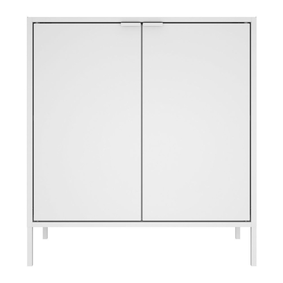
- Page 1 1000010416 - 31/07/2019 Assembly Guide Model: 11GMC1 / 11GMC2 / 11GMC3 / 11GMC4 Double Cabinet Stuck? Questions? We are here to help. 1-888-230-2225 help@manhattancomfort.com...
-
Page 2: Identification Of Parts
In order to ease the assembly, you should separate and identify the parts first Do not place the parts directly onto the floor. Use a cardboard sheet or a mat to place the parts, during the separation and assembly. IMPORTANT In order to avoid severe or even fatal injuries, follow the instructions carefully. - Page 3 ASSEMBLED PRODUCT: H: 29.92'' W:27.55'' L:13.77'' CEILING Maximum weight supported distributed TOP BACK SHELF LEFT SIDE BOTTOM BACK REAR DOOR LEFT RIGHT SIDE FRAME DOOR RIGHT FRAME...
-
Page 4: Hardware List
Hardware list 1000008297 1000008616 1000009033 1000000281 - WHITE 1000007352 - BLACK 1000010221 - BLUE Qty. 2 Qty. 2 Qty. 1 Qty. 2 1000010136 1000008285 3000009645 - WHITE 1000008285 3000009643 - BLACK 3000009649 - BLUE 3000009647 - GREY Qty. 4 Qty. 1 Qty. - Page 5 1 - Check the alignment of the holes on the fitted parts. 2 - The hole in the horizontal bar of part FRAME, should be up. FRAME 1 - With the end of F3, smash the safety claw, locking part FRAME to part LEFT SIDE and RIGHT SIDE.
- Page 6 1- Identify the cutout on the top end of the BOTTOM BACK part. 1 - Attach the BOTTOM BACK part, on the LEFT SIDE, RIGHT SIDE and FRAME parts. 2 - Slide part BOTTOM BACK to support on parts LEFT SIDE and RIGHT SIDE.
- Page 7 1 - With the end of F3, smash the safety claw, locking part BOTTOM BACK to part LEFT SIDE and RIGHT SIDE. 1 - Attach the joint of the front of the REAR part under the BOTTOM BACK part. 2 - Lower the REAR part as indicated.
- Page 8 1 - Check all the fittings before moving forward. REAR 1 - Attach the TOP BACK part with both cutouts facing up, on parts LEFT SIDE and RIGHT SIDE. 2 - Attach the TOP BACK part onto the BOTTOM SIDE part.
- Page 9 1 - With the end of F3, smash the safety claw, locking part BOTTOM BACK to part LEFT SIDE, RIGHT SIDE and BOTTOM BACK.
-
Page 10: Right Side
1 - Attach the CEILING part on the parts LEFT SIDE and RIGHT SIDE. 2 - Pull the front of the CEILING part. - Page 11 1 - With the end of F3, smash the safety claw, locking part TOP BACK to part CEILING. CEILING 1- Slightly turn the SHELF part and place it inside the cabinet, as indicated. 2- Check all the fittings before continuing. SHELF...
- Page 12 IMPORTANT: CABINET MUST BE ATTACHED TO THE WALL 1 - Lay the cabinet against the wall and mark the hole. 2 - Insert the metal part of 1 - Drill the wall on the marked point, using a ½” drill bit. the bushing into the hole until it overcomes the wall.
- Page 13 3 - Pull the bushing driving it against the wall and then push the plastic ring until it leans close to the wall WALL Plastic ring 4 - Break the bushing's rods WALL WALL WALL...
- Page 14 1 - Insert the screw F2 into the hole of part TOP BACK. 2 - Turn screw F2 with part F3 clockwise. 3 - Press part F4 against the heads of the F2 screws. 4 - Attach the F5 into the FRAME part. 1 - Attach the F7 handle to the doors DOOR LEFT and DOOR RIGHT as indicated below DOOR RIGHT...
- Page 15 1 - Attach the F6 into the DOOR LEFT and DOOR RIGHT holes. 2 - Glue F8 to part DOOR RIGHT in the indicated area.. DOOR LEFT DOOR RIGHT 1 - Attach part DOOR RIGHT to the right side of the enclosure on parts F5 and FRAME.
- Page 16 ITEMS EXCLUDED FROM WARRANTS This limited warranty does not cover: 1. In-home service including, but not limited to, service calls to correct the installation of any Manhattan Comfort Smart Diy products or to instruct the consumer on how to use or install them.
Need help?
Do you have a question about the 11GMC1 and is the answer not in the manual?
Questions and answers