
Related Manuals for AnaJet FP-125


Summary of Contents for AnaJet FP-125
- Page 1 _____________________________________ ..………………………………………………………… ..Replacing Print Engine Board (PCB) Technical Support Version # 1.0 Date 6/7/2012...
-
Page 2: Contact Info
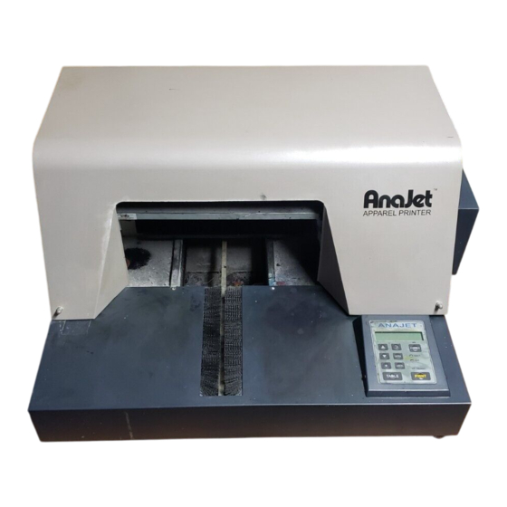
Technical Support Contact Info Corporate Office: AnaJet Inc. 3050 Redhill Ave Costa Mesa, CA 92626 Telephone: 714.668.6000 Toll Free: 877-6-ANAJET (877.626-2538) 714.662.3600 Fax: Revision History Revision Description Author Date Initial release. Edsel Barrios– Tech support 6/8/2012 Replacing print engine EXAMPLE board. - Page 3 Introduction This is a troubleshooting guide on how to replace a Print engine board (PCB). Scope This applies to FP-125/Sprint printers only. Symptoms Printer is looping in Auto System Maintenance. Printer stuck in reset service counter (only in more severe cases) Possible causes Static electricity blowing out F1 or F2 fuse on print engine board.
- Page 4 Technical Support Once the cover has been removed your printer should look like this. Step 2. Next we need to remove the lid of the printer. Inside the printer you will see the strut the holds the lid open. The strut is held by a small E clip. You will need needle nose pliers or a small knife to remove this piece.
- Page 5 Technical Support Once the lid is removed your printer should look like this. Troubleshooting – Title for the guide Page 5 of 9...
- Page 6 Technical Support 4. We must now remove the cover for the print engine board (PCB). There will be 8 screws 2 on each side and 4 on the USB side. Troubleshooting – Title for the guide Page 6 of 9...
- Page 7 Technical Support Troubleshooting – Title for the guide Page 7 of 9...
- Page 8 Technical Support Once the 8 screws are removed you will be able to pull up the board cover. Be very careful when removing the cover you don’t want to damage any cables. Once the cover is removed your printer should look like this. 5.
- Page 9 Technical Support When the damaged board is removed replace with the new one and plug in all the cables back. Each ribbon cable is labeled and the board has the same labels printed on them as well. Make sure all cables are plug in before powering up the printer. When the board is back in you can start putting the printer back together.
Need help?
Do you have a question about the FP-125 and is the answer not in the manual?
Questions and answers