Sign In
Upload
Download
Table of Contents
Contents
Add to my manuals
Delete from my manuals
Share
URL of this page:
HTML Link:
Bookmark this page
Add
Manual will be automatically added to "My Manuals"
Print this page
×
Bookmark added
×
Added to my manuals
Manuals
Brands
Atlas IED Manuals
Amplifier
AZA Series
Owner's manual
Atlas IED AZA Series Owner's Manual
Digital power amplifiers
Hide thumbs
1
Table Of Contents
2
3
4
5
6
7
8
9
10
11
12
13
14
15
16
17
18
19
20
21
22
23
24
page
of
24
Go
/
24
Contents
Table of Contents
Bookmarks
Table of Contents
Table of Contents
Important Safety Instructions
Introduction
Key Features
AZA Amplifier Configuration
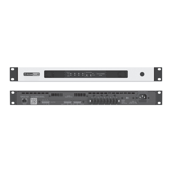
Front Panel Description
Rear Panel Description
Changing from 115V - 120V to 220V-240V Operation
Rack Ear Installation
Locating the AZA on a LAN
Direct Connection Via Ethernet
II. Web Browser Via Network Router
Atlasied AZA IP Discovery Software
Logging into the Amplifier
Change Login Username and Password
AZA UI Overview
Output Channel Indicators
Output Channels Level Meters
Output Channel Limiter & Clip / Fault Indicators
Output Channel Mute
Amplifier Load Settings
Auto Power down Settings
Front Panel Power Switch Settings
AZA Factory Default Settings
Identifying the Firmware Version
Static IP
Resetting to Factory Default
Accessory Card Installation
Installation and Considerations
Specifications
Warranty
Advertisement
Quick Links
1
Aza Amplifier Configuration
2
Locating the Aza on a Lan
3
Logging into the Amplifier
4
Resetting to Factory Default
Download this manual
AZA404 / AZA804
Digital Power Amplifierpers
1601 JACK MCKAY BLVD.
ENNIS, TEXAS 75119 U.S.A.
TELEPHONE: (800) 876-3333
SUPPORT@ATLASIED.COM
– 1 –
AtlasIED.com
Table of
Contents
Previous
Page
Next
Page
1
2
3
4
5
Advertisement
Table of Contents
Need help?
Do you have a question about the AZA Series and is the answer not in the manual?
Ask a question
Questions and answers
Related Manuals for Atlas IED AZA Series
Amplifier ATLAS IED AA35G Owner's Manual
Commercial mixer amplifier (16 pages)
Amplifier ATLAS IED AA60G Owner's Manual
Commercial mixer amplifier (16 pages)
Amplifier Atlas IED AA120G Owner's Manual
Commercial mixer amplifier (20 pages)
Amplifier Atlas IED AA240G Owner's Manual
Commercial mixer amplifier (20 pages)
Amplifier Atlas IED AZA804 Owner's Manual
Digital power amplifiers (24 pages)
Amplifier Atlas IED AAGRMK2 Install Sheet
Amp rack mount kit (2 pages)
Amplifier ATLAS IED TSD-PA252G Owner's Manual
2x25w global audio amplifier (13 pages)
Amplifier ATLAS IED TSD-DA28 Owner's Manual
2x8 balanced line distribution amplifier (13 pages)
Amplifier ATLAS IED TSD-ML11 Owner's Manual
1x1 mic/line preamp (17 pages)
Amplifier ATLAS IED DPA404 Owner's Manual
Digital power amplifier dpa series (40 pages)
Amplifier Atlas IED TitanONE T112 Installation Manual
Smart mainframe power amplifier (24 pages)
Amplifier Atlas IED HPA Series Owner's Manual
Multi-impedance high power amplifier (20 pages)
Amplifier Atlas IED TSD-PA122G Owner's Manual
2x12w global audio amplifier (13 pages)
This manual is also suitable for:
Aza404
Aza804
Table of Contents
Print
Rename the bookmark
Delete bookmark?
Delete from my manuals?
Login
Sign In
OR
Sign in with Facebook
Sign in with Google
Upload manual
Upload from disk
Upload from URL


Need help?
Do you have a question about the AZA Series and is the answer not in the manual?
Questions and answers