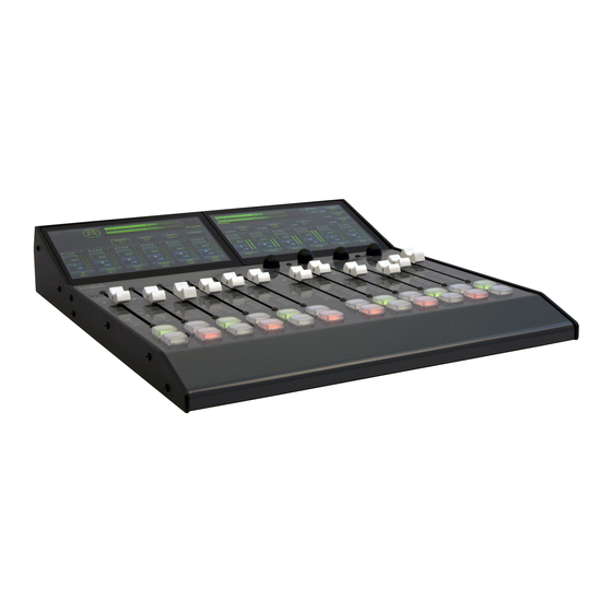
Logitek mixIT Setup Manual

Audio console system, audio engine
Hide thumbs Also See for mixIT:

Advertisement

Logitek mixIT Audio Console System Setup Manual
Logitek JET67 Audio Engine Manual
Version 1.0
May 2020

Advertisement

Table of Contents
loading

Summary of Contents for Logitek mixIT

  • Page 1 Logitek mixIT Audio Console System Setup Manual Logitek JET67 Audio Engine Manual Version 1.0 May 2020...
  • Page 2 Contents ã 2020 Logitek Electronic Systems, Inc. Notice Every effort has been made to supply complete and accurate information. However, Logitek Electronic Systems, Inc. assumes no responsibility for its use, nor any infringement of patents or other rights of third parties, which would result.
  • Page 3: Table Of Contents

    ................................38 AIR OUTPUT ..............................39 ADER PERATION ................................40 .................................. 40 ALKBACK ......................41 TUDIO UEST EADPHONES ONITOR ONTROLS ................................ 42 TILITY OUTERS ................................43 CENE ELECTS TWO YEAR LIMITED WARRANTY ......................... 44 Logitek mixIT Audio Console System/JET67 Manual...
  • Page 4: Chapter 1 - Introduction

    AoIP. The mixIT is powered by the JET67 Audio Engine. The JET-67 is where all of the audio and network connections are made. It also delivers power to the audio console. We designed the JET67 to have sufficient inputs and outputs to connect most studio equipment for the room based on fader size.
  • Page 5: Model Numbers

    The mixIT console is not compatible with the Logitek AE-32 Audio Engine. Model Numbers Figure 2 - The mixIT-12 Console mixIT-12 The mixIT-12 console is a kit that contains the following: MIXIT-C12 mixIT 12 Channel Surface JET67 JET67 Audio Engine with 2 J67-I/O cards installed.
  • Page 6: Mixit-6

    Figure 3 - The mixIT-6 Console mixIT-6 The mixIT-6 console is a kit that contains the following: MIXIT-C6 mixIT 6 Channel Surface JET-67 JET67 Audio Engine with 1 J67-I/O cards installed This system contains: • 6 fader touchscreen controlled audio console •...
  • Page 7: Jet-67 Dante

    KTRU, the pair decided they could design a better one themselves and the company was born. In the late 1990s, Logitek was the first North American company to offer a router-based digital console. Its first virtual PC-based console was introduced in 1999. By 2009, the company had pivoted to television, offering both physical and virtual consoles that seamlessly interface to production workflow automation systems.
  • Page 8: Chapter 2 - System Configuration

    • A computer running Windows 10 • An Ethernet adapter to connect your computer to the JET67 • JetStream Server, available at https://logitek.link/XXXXXXX • A web browser, such as Chrome, Internet Explorer, or Microsoft Edge. Firefox is not supported. Connecting the Console to the JET-67 Audio Engine Using the supplied standard CAT-5 cable, plug one end into the RJ-45 port on the back of the JET-67 and the other end into the RJ-45 port on the back of the console.
  • Page 9: Audio Connections Overview

    The JET67 works best with balanced audio. If you have an unbalanced input, we recommend jumpering negative to ground. Unlike a traditional audio console, the mixIT controls an audio router. Therefore, you’ll notice there isn’t an output that’s labeled “program” or “monitor.” You decide where you want to wire your inputs and outputs and then configure everything in the software.
  • Page 10: Connecting Your Computer To The Jet67

    The configuration will remain in memory on the JET67 even if power is disconnected. You can save the configuration in a JET67 to an .XLS file and keep it backed up and you can restore that .XLS file to the JET67 using JetStream Server. Install JetStream Server Logitek mixIT Audio Console System/JET67 Manual...
  • Page 11: Connect Your Pc To The Jet67

    Connect Your PC to the JET67 1. Connect the mixIT directly to the JET67 jack marked “Console” with the supplied CAT-5 cable. 2. Connect the JET67 to power if not already plugged in. 3. Plug one of the Ethernet ports on the back of the JET67 to your local network OR plug an Ethernet cable from your PC directly into one of the Ethernet ports on the back of the JET67.
  • Page 12 10. Under TCP/IP client, type the IP Address of the JET67 from step 4 in the Remote IP Address field. Set the Remote TCP/IP port to 9500 11. Return to the Set up tab. Figure 8 - JetStream Server, External Protocols, Set up tab Logitek mixIT Audio Console System/JET67 Manual...
  • Page 13 14. Enter 127.0.0.1 into the address bar of your browser and hit enter. 15. You will see the login screen. For username, enter user. Leave the password blank. Click Connect. Figure 9 - The login screen Logitek mixIT Audio Console System/JET67 Manual...
  • Page 14 To add an input or output, click the ‘Add Input’ or ‘Add Outpu’ button over the respective column. To edit an input or output, click on the box for the desired input or output. Logitek mixIT Audio Console System/JET67 Manual...
  • Page 15: Creating Or Editing A Microphone Input

    2. Enter a Unique Name to identify the input. 3. Set the Number of Channels to 1. 4. Set the Lf channel to the input number. Valid numbers on a mixIT-12 are 1-4. Valid numbers on a mixIT-6 are 1-2.
  • Page 16 11. Click Upload to JetStream to save your changes. 12. To delete this source, click Delete this local input. 13. To cancel and return to the Local IO page, click Cancel edit changes. Logitek mixIT Audio Console System/JET67 Manual...
  • Page 17: Creating Or Editing An Analog Input

    4. Set the Lf channel to the left analog input number and the Rt to the right analog input number. (if mono, there will only be the Lf box to fill.) Valid numbers on a mixIT-12 are 1-12. Valid numbers on a mixIT-6 are 1-6.
  • Page 18: Creating Or Editing A Digital Input

    1 on left and microphone 2 on right.) In this case you would set number of channels to 1 and select 1, 2, 3, or 4 as desired. For all other settings, follow the analog input instructions. Logitek mixIT Audio Console System/JET67 Manual...
  • Page 19 Logitek mixIT Audio Console System/JET67 Manual...
  • Page 20: Creating Or Editing A Local Output

    Mono Ax1 – the Aux 1 bus, summed to mono Router 1 Out – the output to Router 1, the left widget on the mixIT fader display. Router 2 Out – the output to Router 2, the middle router widget on the mixIT fader...
  • Page 21 Router 3 Out – the output to Router 3, the right router widget on the mixIT fader display The Available Sources column on this page does NOT have a function on the JET67. If you route a stereo mix to a mono output, the JET67 will send left channel only.
  • Page 22: The Network Io Page

    Usually used for talk studio monitor speakers or for guest headphones. Phones Out – the headphone monitor output. This corresponds to the Headphone volume knob on the console. Usually used to feed the headphone amp of the console Logitek mixIT Audio Console System/JET67 Manual...
  • Page 23 Router 2 Out – the output to Router 2, the middle router widget on the mixIT fader display Router 3 Out – the output to Router 3, the right router widget on the mixIT fader display 5. Click Upload to JetStream to save. Click the Cancel Edit Change button to exit without saving.
  • Page 24: Inputs From Network

    At Logitek, our solution to this dilemma was to identify the three biggest AoIP systems on the market, license them, and then create an internal channel guide that searches for all three and builds a list in the JET67 of what’s available on the network.
  • Page 25 GPI Inputs (valid numbers are 1-4) Audio On – enter the GPI Input where a contact closure will turn the channel on. Audio Off – enter the GPI Input where a contact closure will turn the channel off. Logitek mixIT Audio Console System/JET67 Manual...
  • Page 26 Start String: the text to send when the fader turns on Stop String: the text to send when the fader turns off The following checkboxes are relevant to the mixIT: Fader Start: if set to yes, turn the channel on when the fader is raised from zero and off when the fader is returned to zero.
  • Page 27: Surface Settings

    HD Radio diversity delay. In the column for Monitor In, set what selections to choose from in the Control Room monitor selector. Common selections here are program, aux 1-3, air monitor, or an input with a Logitek mixIT Audio Console System/JET67 Manual...
  • Page 28 Route 1, Route 2, Route 3: These are the three router widgets on the right-hand side of the mixIT-12 or the three router widgets on the mixIT-6. Assign tick marks to the sources you want available to be routed by these router widgets the same way you assign sources to the console faders..
  • Page 29: Dsp Settings

    Also, under inputs, click on Router 1/Router 2/Router 3 to change the name displayed under the router widget. This is useful to name the router for its destination. Logitek mixIT Audio Console System/JET67 Manual...
  • Page 30: Mix Minus Tab

    The mixIT has 12 mix minus buses. You will tag the inputs, either local or network by editing them and entering the mix minus number and saving it. Then here on the DSP settings page you will define the mix minus bus and turn it on.
  • Page 31 Once you have saved this, the mixIT system will be creating a mix minus and when you route it to an output you will hear the mix.
  • Page 32: Control Settings

    Up to three tallies can be defined per mute group to turn on multiple on air lights, logging skimmers, and the like. Logitek mixIT Audio Console System/JET67 Manual...
  • Page 33: Dante Setup

    Dante Setup Coming Soon Dante for the JET67 is in development as of this writing. This section will be updated when the Dante card is shipping.
  • Page 34: Wiring Diagrams

    The JET67 uses 5 pin European-style terminal blocks, commonly known as Phoenix connectors. These solderless terminal blocks are easy to connect. They are grouped as follows: In 1 In 2 mixIT-6 and mix-IT-12 Out 1 Out 2 mixIT-6 and mix-IT-12...
  • Page 35 Out 3 Out 4 mixIT-6 and mix-IT-12 Out 5 Out 6 mixIT-6 and mix-IT-12 Out 7 Out 8 mixIT-6 and mix-IT-12 In 3 In 4 mix-IT-12 only Out 9 Out 10 mixIT-12 only Logitek mixIT Audio Console System/JET67 Manual...
  • Page 36: Gpio

    6. Out-6 14. In-4 7. Out-Common 15. Out-8 8. Ground Inputs grounded to activate. The maximum input is 12 volts. The outputs are opto-isolated electronic relays. The maximum load is .5 amps at 50 volts. Logitek mixIT Audio Console System/JET67 Manual...
  • Page 37: Console Operation

    Console Operation The mixIT is very easy to use. The console uses touchscreens to select sources and bus assignments and knobs and buttons to adjust levels and turn faders on and off. This gives the operator the best of both worlds: simple menus and fewer buttons while still allowing someone to operate the board on air by feel without looking at where their hands are going.
  • Page 38: Bus Assignments The Console Has 4 Main Mix Buses : Program , Aux 1, Aux 2, And Aux 3. Usually Program Is The Main On Air Output

    As with changing the route, tap the name of the source over the fader you wish to change. Tap P (Program), 1 (Aux 1), 2 (Aux 2), or 3 (Aux 3) to assign the fader to the mix bus. When you have made your selections, tap “Done.” Logitek mixIT Audio Console System/JET67 Manual...
  • Page 39: Fader Operation

    To turn a channel on, press the top push button under the fader. The on button will glow green. To turn a channel off, press the lower push button under the fader. The off button will glow red. Logitek mixIT Audio Console System/JET67 Manual...
  • Page 40: The Cue Bus

    (for example, a codec for remote broadcasting), tapping the Talk button will route the studio talkback microphone (as defined in surface settings) to the mix minus output. Tap the button again to turn talkback off and resume sending mix minus to the output. Logitek mixIT Audio Console System/JET67 Manual...
  • Page 41: Studio/Guest, Headphones, Monitor Controls

    The Studio/Guest, Headphone, and Monitor selectors are on the far right. Tap the source to change what audio is being fed to these outputs. The volume knobs below the screen will adjust the level. Logitek mixIT Audio Console System/JET67 Manual...
  • Page 42: Utility Routers

    There are three utility routers on the console that can be used to change what is fed to the air chain, recorders, or remote codecs. Tap the box for the router to change the input. Logitek mixIT Audio Console System/JET67 Manual...
  • Page 43: Scene Selects

    Scene Selects There are 4 scene select buttons on the mixIT-12. Different console profiles can be stored to those buttons in setup. Press the button to recall the scene. Logitek mixIT Audio Console System/JET67 Manual...
  • Page 44: Two Year Limited Warranty

    LOGITEK will thereafter ship a replacement part, freight prepaid. LOGITEK may require the purchaser to return the defective part to LOGITEK freight prepaid as a condition of such replacement, either before or after LOGITEK ships the replacement part. LOGITEK shall not be responsible for any other charges or liabilities associated with purchaser-made repairs.

This manual is also suitable for:

Jet67

Table of Contents