
Related Manuals for Logitek Pilot


Summary of Contents for Logitek Pilot
- Page 1 Logitek Electronic Systems Logitek Electronic Systems Pilot Reference Manual Revision 1.0 Oct 2010...
- Page 2 Logitek Electronic Systems, Inc. Logitek, JetStream, and Pilot are trademarks of Logitek Electronic Systems, Inc. All other trademarks acknowledged.
-
Page 4: Document Revisions
Document Revisions Date Revision Author Notes September 2010 Paul Dengate Preliminary release of Pilot manual October 2010 John Davis, CBNT First release of Pilot manual Logitek Pilot Reference Manual... -
Page 5: Table Of Contents
1 Introduction..........................6 2 Unpacking 10 3 Physical Installation........................ 11 4 Configuration........................... 17 5 Operation 23 6 Maintenance..........................26 Appendix A Release Notes......................29 Appendix B Specifications......................30 Appendix C Pinouts........................32 Two Year Limited Warranty...................... 33 Logitek Pilot Reference Manual... -
Page 6: Introduction
1 Introduction About this Manual This manual describes the installation and operation of the Logitek Pilot control surface. Intended Audience This manual is aimed at Engineers responsible for installing, configuring and supporting a Logitek Networked Console System with the Pilot surface. - Page 7 The Pilot is not compatible with the Logitek Audio Engine. The Pilot surface can be configured with 6, 12, 18 or 24 Faders. There is also a Monitor Module containing the Monitoring and Selection functions. The module types include: 6 Fader Module ...
-
Page 8: System Requirements
System Requirements Pilot is designed to connect to a Logitek JetStream running DSP version 4.x. Contact Logitek Electronic Systems or your reseller if you are unsure of compatibility, or are adding a Pilot surface to a pre-existing Logitek facility. System Architecture Put simply, the Pilot surface is just a remote control panel for the JetStream. - Page 9 Pilot is designed for use ONLY with the JetStream Router v4.x. The Pilot retains compatibility with other surfaces for the majority of its features. Following is the minimum software release version/date that is required for Pilot support on a JetStream Router v4.x system.
-
Page 10: Unpacking
2 Unpacking This section details what you should do when unpacking your newly arrived Pilot surface. Parts List The exact list of parts received will vary depending on your order, but should generally include: 1 x Pilot Power Supply (external brick-style) ... -
Page 11: Physical Installation
3 Physical Installation The Pilot surface is designed to be mounted on a desk in a semi-permanent studio installation. The Meter Bridge, if optioned, can be screwed to the back of the Pilot. Power Supply Unit The Power Supply Unit is an external brick-style supply. - Page 12 JetStream and the console begins to receive meter data. Mounting The Meter option is supplied separately and attaches to the back of the Pilot frame with two screws (included). The ribbon cable from the Meter attaches to an internal header via a small ribbon cable. The blue side of the ribbon cable should be up.
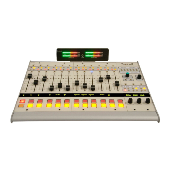
- Page 13 Figure 3: Pilot with Meter Bridge Logitek Pilot Reference Manual...
- Page 14 The Pilot is powered by an external 12VDC 40W power supply, included with the console. Connect the supply to mains using an IEC style inlet lead and the 12VDC to the rear of the Pilot. The included supply can be replaced by any similar unit.
- Page 15 Frame to JetStream The Pilot Frame connects to the Logitek JetStream Router using a balanced serial link. Connection from the Pilot to a JetStream Router JSM-DSP card is via a straight-through RJ45 cable (CAT5 or better is recommended). You can use a dedicated CAT5 patch cable or existing structured cabling. If using structured cabling systems, care should be exercised to ensure the serial connections are not confused with other network outlets and that the link is not unintentionally “un-patched”.
- Page 16 GPI connections are on a single DB25 connector on the rear of the Pilot frame. As wiring schemes vary from station to station, these cables are not supplied with the surface, but are available from Logitek Electronic Systems. They can also be purchased from local suppliers in the required form.
-
Page 17: Configuration
Configuration of the JetStream Router is done in AEConfig. Currently, AEConfig does not include specific DSP table entries for the Pilot. You should use a Mosaic surface of the appropriate size when configuring a Pilot. In the future, specific Pilot support will be added to AEConfig, however, the two consoles are compatible in DSP allocations. - Page 18 In Pilot v1.x the Device Number of a module is determined by its firmware and position. Dual Controls / Split Consoles The Pilot does not support Dual Controls or Split Consoles. It is designed as a single self-contained console. Softkey Addressing The twelve softkeys on the monitor module follow the Numix Bridge Button addressing scheme, therefore the Bridge Button and Bridge Lamp keywords in Command Builder may be used.
- Page 19 Port 2 – Button device 50/lamp device 4F Button Port 3 – Button device 64/lamp device 63 Button Figure 6: Pilot softkey buttons The softkeys may be labeled by replacing the paper legend under the Lexan overlay. Logitek Pilot Reference Manual...
- Page 20 Two of these hotkeys are labeled on the console: P (Program) and 1 (Aux 1). The other two may be labeled by replacing the paper legend under the Lexan overlay. Logitek Pilot Reference Manual...
- Page 21 Device 4D Device 4B Device 62 Device 65 Device 61 Alternatively, d[device] notation in Command Builder, such as d[Port1 Monitor In] is valid and will be properly translated by Command Builder. Figure 7: Monitor Hotkey Bus Numbers Logitek Pilot Reference Manual...
- Page 22 Port (Surface) Number Device Number In Command Builder, sources should be routed to d[Port1 Monitor Meter In] (or appropriate port number) using the Alt+D pick list. Command Builder will translate this into the appropriate hex device number. Logitek Pilot Reference Manual...
-
Page 23: Operation
5 Operation Your Logitek Pilot console has been designed for easy and quick access to the functions you most need. If you’ve had experience with broadcast consoles before, you’ll soon be at home, finding your way around quite easily. Logitek Electronic Systems has been manufacturing broadcast consoles for decades, so we understand how to make control surfaces that are both powerful and straightforward. - Page 24 Cue button – Press to listen to the source through the internal cue speaker Phone 1 regardless of fader position or whether the channel is on or off. Fader – Adjusts level for the selected mixing busses. button – Turns channel on button – Turns channel off Logitek Pilot Reference Manual...
- Page 25 Press – user changeable legend strip – TAKE to accept, or CANCEL to cancel the change. Use the CUE knob to increase (clockwise) or decrease (anticlockwise) the level going to the Pilot’s Cue speaker. SELECT CANCEL TAKE Use the CNG buttons to access the source change function for each of the monitoring destinations.
-
Page 26: Maintenance
6 Maintenance The Pilot uses multi-layer boards with surface mount technology. As such, the majority of the console is not user-serviceable. However, there are some basic tasks that can be performed by suitably qualified technical personnel. Warranty Logitek Electronic Systems will honor the warranty of the system when conducting field maintenance, provided: ... - Page 27 6. Fit the replacement fader to the module using the two hew screws. 7. Replace the slider cap. 8. Reconnect the fader connector, ensuring the same polarity as the other faders on the module. 9. Replace the module in the frame, and screw it back in. Logitek Pilot Reference Manual...
- Page 28 Modules are fully hot-swappable – they will refresh their status shortly after powering up. More Assistance If you would like more assistance with maintenance and service, please contact Logitek or your reseller. Logitek Pilot Reference Manual...
-
Page 29: Appendix A Release Notes
Appendix A Release Notes Known Issues The following issues have been reported and are under investigation. Logitek Pilot Reference Manual... -
Page 30: Appendix B Specifications
Features The Monitor Module provides the following features: Contains controls for main monitor, cue speaker, operator headphone, studio monitor and guest headphone Studio, Monitor, and Operator Headphones each have 4 input select hotkey buttons Logitek Pilot Reference Manual... -
Page 31: Meter Bridge
One meter always shows program, one meter is switchable LED indicator for studio and microphone tally Pilot Power Supply Voltage 110 - 230 VAC, automatically selected Frequency 47 - 63 Hz Consumption 40 W maximum Logitek Pilot Reference Manual... -
Page 32: Appendix C Pinouts
GPI Out 7a GPI Out 7b GPI Out 8a GPI Out 8b GPI Out 9a GPI Out 9b GPI In 1 GPI In 2 GPI In 3 GPI In 4 GPI In 5 GPI In 6 Ground Logitek Pilot Reference Manual... -
Page 33: Two Year Limited Warranty
The warranty and remedies set forth herein are exclusive and in lieu of all others, oral or written,express or implied. No Logitek dealer, distributor, agent, or employee is authorized to make any modification or addition to this warranty. Logitek Pilot Reference Manual...
Need help?
Do you have a question about the Pilot and is the answer not in the manual?
Questions and answers