Table of Contents
Advertisement
Advertisement
Table of Contents

Related Manuals for NCR RealPOS 5977


Summary of Contents for NCR RealPOS 5977
- Page 1 User Guide NCR RealPOS 5977 Customer Display Release 1.0 BCC5-0000-5141 Issue D...
- Page 2 NCR, therefore, reserves the right to change specifications without prior notice. All features, functions, and operations described herein may not be marketed by NCR in all parts of the world. In some instances, photographs are of equipment prototypes. Therefore, before using this document, consult with your NCR representative or NCR office for information that is applicable and current.
- Page 3 Audience This book is written for hardware installer/service personnel, system integrators, and field engineers. Note: This document is NCR proprietary information and is not to be disclosed or reproduced without consent. Safety Requirements The NCR RealPOS 5977 Customer Display conforms to all applicable legal requirements.
- Page 4 Grounding Instructions In the event of a malfunction or breakdown, grounding provides a path of least resistance for electric current to reduce the risk of electric shock. This product is equipped with an electric cord having an equipment-grounding conductor and a grounding plug.
- Page 5 Equipment Provider, NCR Customer Service or your Service Provider to diagnose the failure to the component level. A replacement component can be acquired by contacting the NCR Customer Satisfaction Hotline between the hours of 8AM and 5PM EST, Monday - Friday: •...
- Page 6 • Improper use or unauthorized modifications of the product. • Inadequate location or surroundings. Site installation must conform to guidelines listed in this document, the NCR Workstation and Peripheral AC Wiring Guide, and the NCR Ethernet Communications Wiring Guide. For detailed warranty arrangements please consult your contract documents.
-
Page 7: Table Of Contents
Table of Contents Chapter 1: Product Overview Introduction Available Models Hardware Features Software Requirements for the NCR 5977 Hardware Retail Platform Software 5977 Line Display 2x20 Utility Service Support Utility Character Sets Chapter 2: Site Preparation Physical Environment Working Range Extreme Power–On... - Page 8 Safety Requirements Servicing the Display Normal Operation Troubleshooting Procedures Servicing the 5977 Customer Display Cleaning the Display Chapter 5: NCR 5977 2x20 Display Programming Host/Retail Display Command Interface Character Scrolling Rate Retail Display Commands Reset Display Erase Display Invalid Command...
- Page 9 Code Page 101 (Katakana) Code Page 866 (Cyrillic) Code Page 775 (Baltic) Code Page 852 (Polish) Code Page 853 (Multilingual Latin with € symbol) Chapter 6: NCR 5977 Graphical Display Programming Host/Retail Display Command Interface Retail Display Commands Backspace Horizontal Tab...
- Page 10 viii Single Byte Code Page Select Vertical Scroll Horizontal Scroll Overwrite Mode Brightness Level Adjustment Character Sets Chapter 7: Retail Platform Software Introduction Retail Platform Software for Windows (RPSW) Retail Platform Software for Linux (RPSL) Installation Procedure Downloading the Installer for Retail Platform Software Installing the Retail Platform Software Windows Linux...
- Page 11 Linux Uninstalling the Software Windows Linux Control the Service Stopping the Service Windows Linux Running the Service Windows Linux Using the Default Settings Windows Linux Brightness Level Adjustment Change the Brightness Level Windows Linux Appendix A: NCR 5977 Migration Path...
- Page 12 Revision Record Issue Date Remarks Feb 2017 First Issue Dec 2017 Added 5977-2000 Graphical Customer Display Removed RS232 Interface Cable (with Power Connector) Added Programming chapter for 5977 Graphical Customer Display Added Migration Path information Dec 2018 Added 5977–1001 2x20 Customer Display, Next Gen White Feb 2020 Added 5977 connector pinouts information...
-
Page 13: Chapter 1: Product Overview
Code pages are stored in the Flash Memory with data retention of at least 10 years. The NCR 5977 display is built in a slim, thin chassis and zero bezel but still maintains the NCR’s strong reputation being retail hardened. It is powered through the terminal using a customized +12 USB plus power or a +12 Powered RS232. -
Page 14: Hardware Features
Product Overview Hardware Features 5977–1000 5977–2000 Display • 2x20 Character LCD Display • 256x64 Graphic Vacuum Fluorescent Display (VFD) • LCD Technology: Black Nematic • 5x7, 8x16, and 16x16 pixel • 7x9 pixel characters characters • Minimum character height of •... - Page 15 Product Overview 5977–1000 5977–2000 Cables • Custom Powered RS232 Cable • Custom USB +Power Cable • Non–Powered USB Cable with over-molded power sockets • 1.3–m and 4–m cable length options • Clean (hidden) cable management Character Sets • Remote Firmware and Character Pre-loaded with ten single–byte and Firmware Set Flashing...
-
Page 16: Software Requirements For The Ncr 5977 Hardware
• Code Page Utility—enables user to load, add, and replace character sets in the NCR 5977 display Unlike the ROM Flasher, the NCR 5977 Code Page Utility is designed solely for the NCR 5977 2x20 LCD Line Display. Note: For more information on these software utilities, refer to Chapter 7, “Software Utility.”... -
Page 17: Character Sets
• 2 Mbit Flash Memory for support of not less than 20 character sets • NCR 5977 2x20 display— pre–installed with three standard character sets • NCR 5977 Graphical display — pre–installed with ten standard single–byte character sets and four double–byte character sets Note: For more information on character sets, refer to the “Character Sets”... -
Page 18: Chapter 2: Site Preparation
Site Preparation Chapter 2: This chapter describes the installation process including site considerations, operating conditions, mounting options, and connections. Physical Environment The working range, storage, and transit environments are presented in the following tables: Working Range Condition Range Temperature 5°C to 45°C (41°F to 113°F) Temperature Change 10°C (50°F) / Hour Dew Point... -
Page 19: Storage Environment
Site Preparation Storage Environment For periods up to three months: Condition Range Temperature –10°C to 50°C (–4°F to 122°F) Temperature Change 15°C (59°F) / Hour Humidity 10% to 90% RH Barometric Pressure 105,000 to 70,000 Pa Transit Environment For periods up to one week: Condition Range Temperature... -
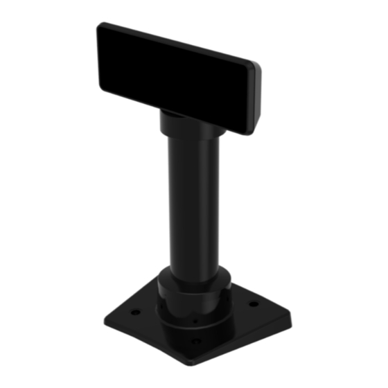
Page 20: Dimensions
Site Preparation Dimensions... -
Page 21: Pole Dimensions
Site Preparation Pole Dimensions There are four different length posts available, in four inch increments. Note: Heights greater than 215 mm (8.5 in.) should be screwed to the counter top. -
Page 22: Base Plate Mounting Hole Dimensions
Site Preparation 2-10 Base Plate Mounting Hole Dimensions... -
Page 23: Electrical Environment
2-11 Site Preparation Electrical Environment AC Power Requirements • 120 VAC, 60 Hz (US, Canada, and others) through a wall mount power supply • 90 – 264 VAC, 50 – 60 Hz through a Universal Input power supply DC Power Requirements •... -
Page 24: Connector Pinouts
Site Preparation 2-12 Connector Pinouts The 5977 Customer Display can communicate with a USB + Power interface or a Powered RS–232 interface of a host. This section provides 5977 connector pinouts and signal descriptions for both USB and RS–232 interfaces. USB Signal RS–232 Signal +12 Return... -
Page 25: Cable Hole Dimensions
2-13 Site Preparation Cable Hole Dimensions The hole dimensions for routing cables from the Customer Display to a host terminal are explained as follows. RS–232 Interface Cable (Com Power) RS–232 DB9 RS–232 RJ50... -
Page 26: Rs-232 Rj12
Site Preparation 2-14 RS–232 RJ12 USB + Power (12V) USB Type A with Power Connector... -
Page 27: Stand Alone Power Adaptor
2-15 Site Preparation Stand Alone Power Adaptor The Power Adaptor (497–0514661, alias 5915–K100–V001) is used with the USB Interface Cable (non–powered). The Adaptor cable is 6 ft in length. Input 100–240 VAC, 63Hz Output 12VDC, 2.5A... -
Page 28: Chapter 3: Hardware Installation
Chapter 3: Introduction The goal for installing the NCR 5977 Customer Display is for a reasonably trained operator or store manager to fully install the terminal in less than 30 minutes. To qualify as reasonably trained, an installer or store manager must be fluent with the terminology and basic technology of PC hardware and software. -
Page 29: Installation Procedures
3-17 Hardware Installation Installation Procedures 1. Locate the Display Mount within 4 meters (13 ft.) of the host terminal. 2. Determine if the cable should be routed down through the mounting surface or if it should be run on top of the surface. Drill a hole if necessary. 3. -
Page 30: Using Cable Management Bracket
Hardware Installation 3-18 Using Cable Management Bracket 1. Route the display end of the Interface Cable through the Table–Top Mount, the Display Post, the Display Swivel, the Swivel Bracket, and the Cable Management Bracket. 2. Assemble the post components. Note: The raised extension of the Display Swivel is oriented toward the front of the unit, which permits the Display to be tilted to the rear. - Page 31 3-19 Hardware Installation 3. Connect the Interface Cable to the Display Module connector until the latch is engaged. Ensure that the latch is properly engaged by gently tugging on the cable. 4. Slide the grooves of the Cable Overmold onto the tabs of the Cable Management Bracket.
- Page 32 Hardware Installation 3-20 5. Route the excess cable to the right and around the board connector and install the Cable Management Bracket. Insert the tab of the Cable Management Bracket into the slot in the Rear Cover. Pivot the bracket as shown until it snaps into position. Note: Ensure that the cables are not pinched when installing the bracket.
- Page 33 Connect the I/F cable to a powered RS–232 connector on the terminal. Configure the terminal serial port as follows: • For NCR 5977 2x20 Customer Display 9600 baud, 8 data bits, 1 start bit, 1 stop bit, No parity • For NCR 5977 Graphical Customer Display 38400 baud, 8 data bits, 1 start bit, 1 stop bit, No parity •...
-
Page 34: Using Strain Relief Bracket
Hardware Installation 3-22 Using Strain Relief Bracket 1. Route the display end of the Interface Cable through the Table–Top Mount, the Display Post, the Display Swivel, and the Swivel Bracket. Note: The Strain Relief Bracket may be installed later. 2. Assemble the post components. Note: The raised extension of the Display Swivel is oriented toward the front of the unit, which permits the Display to be tilted to the rear. - Page 35 3. Attach the Swivel Bracket to the Display Swivel. 4. Connect the Interface Cable to the Display Module connector until the latch is engaged. Ensure that the latch is properly engaged by gently tugging on the cable. NCR 5977 2x20 Customer Display NCR 5977 Graphical Customer Display...
- Page 36 Hardware Installation 3-24 5. Attach the Strain Relief Bracket. a. Attach the Strain Relief Bracket to the cable, right below the Cable Overmold. b. Carefully pull the cable down so the Strain Relief Bracket fits in the middle of the Swivel Bracket and rests on top of the Display Swivel.
- Page 37 Connect the I/F cable to a powered RS–232 connector on the terminal. Configure the terminal serial port as follows: • For NCR 5977 2x20 Customer Display 9600 baud, 8 data bits, 1 start bit, 1 stop bit, No parity • For NCR 5977 Graphical Customer Display 38400 baud, 8 data bits, 1 start bit, 1 stop bit, No parity •...
-
Page 38: Diagnostics
Hardware Installation 3-26 Diagnostics Note: This section is not applicable to NCR 5977 Graphical displays. The 5977 Customer Display has internal Power Up Diagnostics that occur soon after power–up or if a Reset Display command is received from the host software. -
Page 39: External Memory Character Test
Hardware Installation External Memory Character Test Note: This section is not applicable to NCR 5977 Graphical displays. A separate checksum test is performed on the external Flash. A Character Set has its own checksum byte stored in a specific block of a SPI flash sector. -
Page 40: Chapter 4: Hardware Service
Hardware Service Chapter 4: Safety Requirements Carefully follow these safety requirements before servicing the Retail Display: Warning: This device does not contain any user serviceable parts and should only be serviced by a qualified service technician. Caution: Before servicing the display, disconnect the AC power cord from the retail terminal or PC to which the display is connected. -
Page 41: Servicing The Display
Failure to do so could damage the equipment. Normal Operation Note: This section is not applicable to NCR 5977 Graphical displays. On power–up, the unit displays the firmware part number for 2 seconds, then lights all pixels for 2 seconds, then goes blank and awaits commands from the host. -
Page 42: Cleaning The Display
Hardware Service 4-30 Cleaning the Display Caution: Remove power from the unit before cleaning. When cleaning is required, a soft cloth dipped in a mild detergent can be used to clean the cabinet. Only a damp cloth is required so that no moisture can enter the cabinet. Never spray the cleaner directly onto the unit. -
Page 43: Host/Retail Display Command Interface
NCR 5977 2x20 Display Programming Chapter 5: Host/Retail Display Command Interface The Retail Display accepts two types of data: display data and command data. • If a byte received from the host is any character except the ESC (0x1B) character, it is processed as a character and displayed on the Retail Display. -
Page 44: Retail Display Commands
5-32 NCR 5977 2x20 Display Programming Retail Display Commands The following table describes the Retail Display commands supported: Command Function 1B 01 Reset Display 1B 02 Erase Display 1B 03 Invalid Command 1B 04 Set Diagnostic State On 1B 05... - Page 45 NCR 5977 2x20 Display Programming 5-33 Command Function 1B 21 Select Character Set 2 1B 22 Select Character Set 3 1B 23 Select Character Set 4 (External Memory required) 1B 24 Select Character Set 5 (External Memory required) 1B 25...
-
Page 46: Reset Display
5-34 NCR 5977 2x20 Display Programming Reset Display Format 1B 01 Returns xx yy zz xx=microcontroller status 00 — OK If failure occurs, the firmware performs a loop forever. yy=Flash status 00 — OK, present 01 — Not present FF — Failure... -
Page 47: Erase Display
This state is exclusive from the On and Low Power states. This command causes the firmware to display the current NCR firmware part number of the device (for example, the current firmware part number for the device is 497–0408199) for five seconds and then step through each installed 256–character set (default and user defined) displaying... -
Page 48: Set Display State On
5-36 NCR 5977 2x20 Display Programming Set Display State On Format 1B 05 Description This state is used for normal run–time conditions. This operation instructs the firmware to leave one of the other states and begin performing normal refresh operations. There may be a slight delay before the display reaches the specified brightness setting when exiting the Low Power State. -
Page 49: Enable Cursor
NCR 5977 2x20 Display Programming 5-37 Enable Cursor Format 1B 07 Description This command causes a flashing cursor to be used whenever the Display On state is in force. When the cursor is enabled, the firmware shows a visible flashing cursor at the current cursor position. -
Page 50: Set Screen Save Walk
5-38 NCR 5977 2x20 Display Programming Set Screen Save Walk Format 1B 0A Description This command causes the visible display to walk right to left when the Screen Save timer expires (five minutes). The characters on the 5976 display appear to walk across the corresponding display row from right to left. -
Page 51: Enable Character Blink
NCR 5977 2x20 Display Programming 5-39 Enable Character Blink Format 1B 0D Description The blink attribute is the only modifier which is supported for the display character positions. The attribute itself is not necessarily programmed with each new character code. Rather, each time a new character is received, the current setting of the character blink operator is adopted as the working attribute for the new character. -
Page 52: Move Cursor Right
5-40 NCR 5977 2x20 Display Programming Move Cursor Right Format 1B 10 Description This command moves the cursor one position to the right. When the cursor is at the right end of the upper line, it moves to the left end of the lower line. When the cursor is at the right end of the lower line, it moves to the left end of the upper line. -
Page 53: Move To Specified Position (Or Set Cursor Position)
NCR 5977 2x20 Display Programming 5-41 Move to Specified Position (or Set Cursor Position) Format 1B 13 nn Range 00 ≤ nn ≤ 27 (Hex) Description This command moves the cursor to the specified position. Position 0 is the upper leftmost position and position 27 is the lower rightmost position. -
Page 54: Brightness Adjustment (Default = 2)
5-42 NCR 5977 2x20 Display Programming Brightness Adjustment (Default = 2) Format 1B 17 nn Range 01 ≤ nn ≤ 05 (Hex) Description This command adjusts the brightness of the entire display. Individual characters or display positions are not adjusted. On power up, the default brightness setting is 5 (100%). -
Page 55: Read Display Id String
5-43 Read Display ID String Format 1B 19 Returns “NCR 5977, 497-0499797,V1.14.01,<S/N:(11 bytes)>” in Hex format Note: The quotation marks “” are not part of the string and are not returned. Description This command is a request for the Retail Display to return an ASCII string with detailed product information. -
Page 56: Select Character Set N (Default = 1)
5-44 NCR 5977 2x20 Display Programming Select Character Set n (Default = 1) Format 1B 20 – 1B 33 Description This set of commands chooses one of the six supported internal character sets or, if an external character set is present, one of not less than 20 character sets. -
Page 57: Character Sets
• Code 852 (Polish) • Code 853 (Multilingual Latin with € symbol) Note: To download other code pages, see the NCR website: http://www5.ncr.com/support/support_drivers_patches.asp. If your code page requirements are not included in the website, please file for a SCER request. -
Page 58: Code Page 858 (International)
5-46 NCR 5977 2x20 Display Programming Code Page 858 (International) - Page 59 NCR 5977 2x20 Display Programming 5-47...
- Page 60 5-48 NCR 5977 2x20 Display Programming...
- Page 61 NCR 5977 2x20 Display Programming 5-49...
- Page 62 5-50 NCR 5977 2x20 Display Programming...
- Page 63 NCR 5977 2x20 Display Programming 5-51...
- Page 64 5-52 NCR 5977 2x20 Display Programming...
- Page 65 NCR 5977 2x20 Display Programming 5-53...
- Page 66 5-54 NCR 5977 2x20 Display Programming...
- Page 67 NCR 5977 2x20 Display Programming 5-55...
-
Page 68: Code Page 101 (Katakana)
5-56 NCR 5977 2x20 Display Programming Code Page 101 (Katakana) - Page 69 NCR 5977 2x20 Display Programming 5-57...
- Page 70 5-58 NCR 5977 2x20 Display Programming...
- Page 71 NCR 5977 2x20 Display Programming 5-59...
- Page 72 5-60 NCR 5977 2x20 Display Programming...
- Page 73 NCR 5977 2x20 Display Programming 5-61...
- Page 74 5-62 NCR 5977 2x20 Display Programming...
- Page 75 NCR 5977 2x20 Display Programming 5-63...
- Page 76 5-64 NCR 5977 2x20 Display Programming...
- Page 77 NCR 5977 2x20 Display Programming 5-65...
-
Page 78: Code Page 866 (Cyrillic)
5-66 NCR 5977 2x20 Display Programming Code Page 866 (Cyrillic) - Page 79 NCR 5977 2x20 Display Programming 5-67...
- Page 80 5-68 NCR 5977 2x20 Display Programming...
- Page 81 NCR 5977 2x20 Display Programming 5-69...
- Page 82 5-70 NCR 5977 2x20 Display Programming...
- Page 83 NCR 5977 2x20 Display Programming 5-71...
- Page 84 5-72 NCR 5977 2x20 Display Programming...
- Page 85 NCR 5977 2x20 Display Programming 5-73...
- Page 86 5-74 NCR 5977 2x20 Display Programming...
- Page 87 NCR 5977 2x20 Display Programming 5-75...
-
Page 88: Code Page 775 (Baltic)
5-76 NCR 5977 2x20 Display Programming Code Page 775 (Baltic) - Page 89 NCR 5977 2x20 Display Programming 5-77...
- Page 90 5-78 NCR 5977 2x20 Display Programming...
- Page 91 NCR 5977 2x20 Display Programming 5-79...
- Page 92 5-80 NCR 5977 2x20 Display Programming...
- Page 93 NCR 5977 2x20 Display Programming 5-81...
- Page 94 5-82 NCR 5977 2x20 Display Programming...
- Page 95 NCR 5977 2x20 Display Programming 5-83...
- Page 96 5-84 NCR 5977 2x20 Display Programming...
-
Page 97: Code Page 852 (Polish)
NCR 5977 2x20 Display Programming 5-85 Code Page 852 (Polish) - Page 98 5-86 NCR 5977 2x20 Display Programming...
- Page 99 NCR 5977 2x20 Display Programming 5-87...
- Page 100 5-88 NCR 5977 2x20 Display Programming...
- Page 101 NCR 5977 2x20 Display Programming 5-89...
- Page 102 5-90 NCR 5977 2x20 Display Programming...
- Page 103 NCR 5977 2x20 Display Programming 5-91...
- Page 104 5-92 NCR 5977 2x20 Display Programming...
- Page 105 NCR 5977 2x20 Display Programming 5-93...
-
Page 106: Code Page 853 (Multilingual Latin With € Symbol)
5-94 NCR 5977 2x20 Display Programming Code Page 853 (Multilingual Latin with € symbol) - Page 107 NCR 5977 2x20 Display Programming 5-95...
- Page 108 5-96 NCR 5977 2x20 Display Programming...
- Page 109 NCR 5977 2x20 Display Programming 5-97...
- Page 110 5-98 NCR 5977 2x20 Display Programming...
- Page 111 NCR 5977 2x20 Display Programming 5-99...
- Page 112 5-100 NCR 5977 2x20 Display Programming...
- Page 113 NCR 5977 2x20 Display Programming 5-101...
- Page 114 5-102 NCR 5977 2x20 Display Programming...
- Page 115 NCR 5977 2x20 Display Programming 5-103...
-
Page 116: Chapter 6: Ncr 5977 Graphical Display Programming
The Retail Display accepts two types of data: display data and command data. • If a byte received from the host is any character between 0x20 to 0xFF or a double byte character code, it is processed as a character and is displayed on the NCR 5977 Graphical Display. -
Page 117: Retail Display Commands
6-105 NCR 5977 Graphical Display Programming Retail Display Commands The following table describes the Retail Display commands supported: Command Function Backspace — moves the cursor to the left by one character. Horizontal Tab — moves the cursor to the right by one character. -
Page 118: Backspace
NCR 5977 Graphical Display Programming 6-106 Backspace Format Description This command moves the cursor to the left by one character. Horizontal Tab Format Description This command moves the cursor to the right by one character. Line Feed Format Description This command moves the cursor down to the lower line. -
Page 119: Carriage Return
6-107 NCR 5977 Graphical Display Programming Carriage Return Format Description This command moves the cursor to the left end of the same line. Enable/Disable Cursor Format 1F 43 nn where nn = Display cursor ON/OFF • 00 — Cursor OFF •... -
Page 120: Set Font Size
NCR 5977 Graphical Display Programming 6-108 Set Font Size Format 1F 28 67 01 nn where nn = font size • 01 — 5x7 dot character • 02 — 8x16 dot character Default: nn = 01 Description This command toggles between a 5x7 dot character and 8x16 dot character. This command is also required to enable the 16x16 dot double byte character mode. -
Page 121: Double Byte Code Page Select
6-109 NCR 5977 Graphical Display Programming Double Byte Code Page Select Format 1F 28 67 0F nn where nn = double byte character code page font • 00 — Japanese JISX0208 (Shift JIS) • 01 — Korean (KSC5601-87) • 02 — Simplified Chinese (GB2312-80) •... -
Page 122: Single Byte International Code Page Select
NCR 5977 Graphical Display Programming 6-110 Single Byte International Code Page Select Format 1B 52 nn where nn = International Font Set • 00 — America • 01 — France • 02 — Germany • 03 — England • 04 — Denmark 1 •... -
Page 123: Single Byte Code Page Select
6-111 NCR 5977 Graphical Display Programming Single Byte Code Page Select Format 1B 74 nn where nn = Code Page Select • 00 — CP437(USA – Euro std) • 01 — Katakana – Japanese • 02 — CP850 (Multilingual) • 03 — CP860 (Portuguese) •... -
Page 124: Horizontal Scroll
NCR 5977 Graphical Display Programming 6-112 Horizontal Scroll Format 1F 03 Description This command moves the cursor horizontally one space at a time. The position of the cursor determines the line where the characters scroll. The characters above or below the current cursor position are not affected. -
Page 125: Brightness Level Adjustment
6-113 NCR 5977 Graphical Display Programming Brightness Level Adjustment Format 1F 58 nn where nn = Brightness level setting • 01 — 12.5% • 02 — 25% • 03 — 37.5% • 04 — 50% • 05 — 62.5% • 06 — 75% •... -
Page 126: Character Sets
NCR 5977 Graphical Display Programming 6-114 Character Sets The NCR 5977 Graphical Customer Display is pre–installed with 14 character sets. Single Byte Character Sets • CP437 (International) • Katakana • CP850 (Multilingual) • CP860 (Portuguese) • CP863 (Canadian French) • P865 (Nordic) •... -
Page 127: Chapter 7: Retail Platform Software
Customers are required to download and install the latest version of the NCR Retail Platform Software from http://www5.ncr.com/support/support_drivers_patches.asp. The software includes support for the 5977 line display device. -
Page 128: Installation Procedure
Retail Platform Software Installation Procedure Downloading the Installer for Retail Platform Software The 5977 Retail Platform Software can be downloaded from the NCR website. Perform these steps to download the software: 1. Go to http://www5.ncr.com/support/support_drivers_patches.asp. 2. Select Retail Support Files (Drivers, Firmware, Operating Systems, Platform Software (OPOS/JavaPOS), BIOS, etc.). -
Page 129: Installing The Retail Platform Software
Before you install the Retail Platform Software for Linux (RPSL), make sure to provide the following requirements: • Root permissions • NCR RealPOS (SUSE Linux Enterprise for Point of Service 11 SP1) Run Time Image 01.00.00.00 or greater (kernel 2.6.32.12–0.7) • Sun JVM 1.4.2_03–b02 or greater •... - Page 130 Note: In the <java directory>, specify the directory path of the java binary. Only include this parameter if $JAVA_HOME is not set. Note: In the <path to package>, specify the directory path of the installer package that you downloaded from the NCR website. The Welcome Screen displays. 6. Select Next.
- Page 131 Retail Platform Software 7-119 7. Specify the directory where you want to install the RPSL. The default directory is . To locate another destination directory, select Browse. /opt/NCR/RPSfL 8. Select the terminal class where your 5977 display is connected.
- Page 132 7-120 Retail Platform Software 9. At the Setup Type window, select the installation type that you prefer. 10. Select Next. 11. The application displays your installation details for you to confirm. If you want to change some options, select Back.
- Page 133 Retail Platform Software 7-121 12. After verifying information, select Next. The installation setup begins.
- Page 134 7-122 Retail Platform Software 13. Upon successful installation, the application confirms the completion. Select Finish. Console Mode 1. Open a terminal. 2. Create a new directory by entering the command: mkdir <destination directory>. Note: The RPSL is installed at the destination directory. In this example, the directory is named /mnt/iso 3.
- Page 135 Note: In the , specify the directory path of the installer <path to package> package that you downloaded from the NCR website. 6. The application displays the Welcome message and begins to guide you in the installation process. Press 1.
- Page 136 7-124 Retail Platform Software 8. After specifying the destination directory, press 1. 9. Select the terminal class where your 5977 display is connected. Each terminal is assigned a number. From your keyboard, press the number that corresponds to your terminal. 10.
- Page 137 Retail Platform Software 7-125 11. Press 1 to continue the installation process. 12. Select the installation type that you prefer. Each parameter is assigned a number. From your keyboard, press the number that corresponds to your desired parameter.
- Page 138 7-126 Retail Platform Software 13. The application displays the installation details for you to confirm.
- Page 139 Retail Platform Software 7-127 14. After verifying information, press 1 to continue the installation process. The installation setup begins.
- Page 140 7-128 Retail Platform Software 15. Upon successful installation, the application displays the following message. Press 3 to exit program.
-
Page 141: Uninstalling The Retail Platform Software
_uninst subdirectory of the directory that is selected during installation. The default install directory is /opt/NCR/RPSfL Example: Assuming that default install directory was selected during installation, enter the following command to uninstall the RPSL: /usr/java/jvm/bin/java –jar /opt/NCR/RPSfL/_uninst/uninstall.jar... -
Page 142: Chapter 8: Software Utility
The software supports flashing of firmware into the device connected through the USB or RS–232 serial port. Note: NCR 5977 display uses the same Software Utility as NCR 5976. Note: For more information about RomFlasher, refer to the in the NCR ReadMe.txt... -
Page 143: Installation Procedure
The Software Utility installation includes downloading the installer from the NCR website. The following sections define the installation process. Downloading the Installer The 5977 Line Display Utility can be downloaded from the NCR website. Perform these steps to download the utility: 1. Go to http://www5.ncr.com/support/support_drivers_patches.asp. -
Page 144: Installing The Software
Software Utility 8-132 Installing the Software Windows Extract the ROMFlasher.exe, and then run it as administrator. The following window is then displayed. -
Page 145: Linux
8-133 Software Utility Linux 1. Open a terminal. 2. Install the software by entering the command: rpm –ivh RomFlasher.rpm... -
Page 146: Uninstalling The Software
Software Utility 8-134 Uninstalling the Software Windows Note: No program is installed. The ROMFlasher can be run immediately after downloading and extracting the files. Linux 1. Open a terminal. 2. Verify the version of the installed ROM Flasher by entering the command rpm –qa | grep RomFlasher 3. -
Page 147: Device Firmware
Note: Take note of the firmware version currently installed on your device. Verify if it matches with the latest released version that can be found on the NCR Support page. If they do not match, it is recommended to update the firmware of your device. -
Page 148: Rom Flasher
The ROM Flasher is the software utility that supports firmware update of the 5976 Line Display device and communicates through a USB or RS–232C serial connection. This software is the initial window that displays when you launch the 5976 Software Utility. Note: NCR 5977 uses the same ROMFlasher as NCR 5976. Updating Device Firmware Warning: Please do not disconnect power while updating the firmware. - Page 149 8-137 Software Utility 3. From the Interface section, select the port where the device is connected. • USB—select this option if you are running a USB interface. The Com Port and Baud Rate is grayed out and the default settings are used with this option. •...
- Page 150 Software Utility 8-138 Upon successful firmware flashing, the application displays the Flash Progress with 100%. Note: If the firmware is not successfully flashed or the loaded firmware version is older than the current firmware of the devices, the application displays the error information in the Error box.
-
Page 151: Code Page Utility
8-139 Software Utility Code Page Utility Note: NCR 5977 uses the same Code Page Utility as NCR 5976, that is the 5976 Code Page Utility. The 5976 Code Page Utility is the software utility that enables users to perform the following functions: •... -
Page 152: Downloading The Code Page Input File
1. Go to http://www5.ncr.com/support/support_drivers_patches.asp. 2. Select Retail Support Files (Drivers, Firmware, Operating Systems, Platform Software (OPOS/JavaPOS), BIOS, etc.). 3. Select NCR RealPOS and SelfServ Peripherals (Firmware, Drivers, Utilities). 4. Select Line Displays. 5. Select 5976 and XR7 - F450/451-2x20 Customer Display. -
Page 153: Generating Code Page
8-141 Software Utility Generating Code Page The Code Page Utility includes a Code Page Generator application that converts a 2x20 Retail Display 7x9 dot matrix code set representation into the lowest level databit representations that are used inside the 5976 firmware program. The code set is specified to this program in the form of a text file which represents the 7x9 matrix for each of the 256–member character set. - Page 154 Software Utility 8-142 2. Select CodePage Flasher from the ROM Flasher window. The application displays the 5976 Utility window. Note: The following window displays the code pages for a USB interface connection. To display the existing code pages for the RS–232C connection, select RS–232C from the Interface field.
- Page 155 8-143 Software Utility 6. Select Generate. You can use this output file to add a new output file to a device code page list or to replace an existing file.
-
Page 156: Adding Code Pages
Software Utility 8-144 Adding Code Pages The Code Page Utility permits users to add character sets or replace existing character sets by flashing code pages into devices connected through a USB or RS–232C serial port. The code page used can be a direct output from the Code Page Generator or a predefined code page file which the user can load into the Code Page flasher. - Page 157 8-145 Software Utility 4. Select Flash. The application displays the progress beside the Flash button. Only one device at a time can be flashed with a code page. Make sure to detach the devices you do not wish to flash with the code page. 5.
-
Page 158: Chapter 9: Service Support Utility
Service Support Utility Chapter 9: Introduction Note: This chapter is not applicable to NCR 5977 Graphical displays. The Service Support Utility configures the following settings of the NCR 5977 Line Display device: NCR5976LDServiceSupport ü Flash Firmware ü Flash Additional Code Page ü... -
Page 159: Rom Flasher And Service Support Utility
9-147 Service Support Utility Rom Flasher and Service Support Utility RomFlasher provides the feature of saving settings for the Service Support Utility to be applied to the line display devices. The following settings are saved: • Firmware of the device The utility verifies if the firmware version is lower than the local firmware file version. -
Page 160: Installation Procedure
1. Go to http://www5.ncr.com/support/support_drivers_patches.asp. 2. Select Retail Support Files (Drivers, Firmware, Operating Systems, Platform Software (OPOS/JavaPOS), BIOS, etc.). 3. Select NCR RealPOS and SelfServ Peripherals (Firmware, Drivers, Utilities). 4. Select Line Displays. 5. Select 5976 and XR7 - F450/451-2x20 Customer Display. -
Page 161: Installing The Software
9-149 Service Support Utility Installing the Software Windows 1. Run the installer of the Service Support Utility. The application displays the Welcome screen. 2. Select Next. The License Agreement displays. - Page 162 Service Support Utility 9-150 3. Select I accept the terms in the license agreement. 4. After agreeing to the terms in the license agreement, the application displays the Customer Information window to ask for your name and the name of your organization.
- Page 163 9-151 Service Support Utility 7. At the Setup Type window, select the setup type that you desire. Select Next. 8. Select Install to start installation.
- Page 164 Service Support Utility 9-152 The application displays the installation progress in the following screen. 9. Upon successful installation, the application displays the following window. Select Finish.
-
Page 165: Linux
9-153 Service Support Utility Linux 1. Open a terminal. 2. Install the software by entering the command: rpm –ivh NCR5976LDServiceSupport.rpm... -
Page 166: Uninstalling The Software
Service Support Utility 9-154 Uninstalling the Software Windows 1. From the Start menu, select Control Panel→Programs and Features. 2. From the currently installed program list, select NCR5976LDServiceSupport. 3. Select Uninstall. 4. Confirm the uninstallation window. Linux 1. Open a terminal. 2. -
Page 167: Control The Service
9-155 Service Support Utility Control the Service The configuration settings of the device are automatically activated in the background upon terminal start–up. Stopping the Service To stop the service from running automatically, perform the following steps. Note: The change of start–up type takes effect upon system reboot. Windows 1. -
Page 168: Running The Service
Service Support Utility 9-156 Running the Service To run the service manually, perform the following steps. Windows 1. From the Start menu, select Control Panel→Performance and Maintenance→Administrative Tools→Services. 2. From the services list, select NCR5976LDServiceSupport. Note: If the Service status is already started, select Stop. 3. -
Page 169: Using The Default Settings
9-157 Service Support Utility Using the Default Settings Note: This feature is supported in versions 1.1 or higher. To use the default settings for Windows or Linux, perform either of the following steps. Windows 1. Locate the folder in your Windows directory. 5976LDSettings 2. -
Page 170: Brightness Level Adjustment
Service Support Utility 9-158 Brightness Level Adjustment On power up, the default brightness setting is 5 (100%). Change the Brightness Level To adjust the brightness level of the device, perform these steps. Windows 1. Go to Windows directory ( C:\Windows 2. -
Page 171: Appendix A: Ncr 5977 Migration Path
Appendix A: This section contains information on migration path for customers that are currently using old NCR line display products (NCR 5975 and NCR 5976) and are planning to move to the new NCR 5977 display. NCR 5977 2x20 Customer Display (5977-1000) - Page 172 NCR 5977 Migration Path NCR 5977 Graphical Customer Display (5977-2000) In an event that the NCR 5975 legacy graphical customer display is discontinued, it is recommended that customers move to the new NCR 5977 Graphical Customer Display. The NCR 5977 is not a drop–in replacement for older NCR line display products.
Need help?
Do you have a question about the RealPOS 5977 and is the answer not in the manual?
Questions and answers