
Related Manuals for REMKO PGT 30


Summary of Contents for REMKO PGT 30
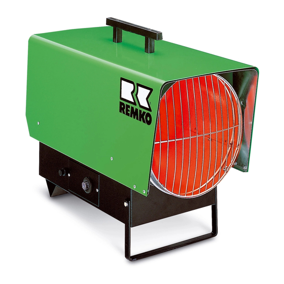
- Page 1 Propane – Heater REMKO PGT 30 – PGT 100 Operation Technology Spare Parts REMKO – strong as a bear. Edition GB– L07...
-
Page 2: Table Of Contents
Contents Contents Page Page Safety hints Drawing PGT 30 General hints List of spare parts PGT 30 Starting 4 – 5 Drawing PGT 60 Putting out of service List of spare parts PGT 60 Fault elimination hints Drawing PGT 100... -
Page 3: Safety Hints
Safety Hints General Hints The unit may be operated only by those persons who When using this unit make sure always to observe have been instructed regarding the unit’s operation the applicable building and fire protection regula- and the handling of liquid gas. tions as well as the rules of the trade cooperative association. -
Page 4: Starting
Starting Heating Operation Plug mains plug into a properly installed mains socket. Make sure to charge a person with the operation of the (230V/1 – 50Hz with fault current breaker!) unit and with the supervision of the reservoirs and of the bottle stock who has been instructed sufficiently regar- ding the handlings concerned. -
Page 5: Putting Out Of Service
Ventilation 2. Automatic Burner Relay When the fault-indicating lamp of Put operating switch into “II” position. In this the automatic burner relay is lit position only the ingoing air fan runs and the up, the reason for the fault has to unit can be used for air circulation. -
Page 6: Maintenance
Maintenance Removal and Cleaning of the Gas Burner Remove protective exhaust lattice and outer casing Depending on the operation conditions the units are to and disassemble inspection cover from the lower be tested by an expert when necessary, but at least re- side of the unit. -
Page 7: Action In The Case Of Faults
Action in the Case of Faults Faults: Cause: - Unit does not start 1 – 2 – 3 – 4 – 5 – 7 – 10 – 13 – 17 – 18 - Unit switches off during operation (fault-indicating lamp in 2 –... -
Page 8: Drawing Pgt
Drawing PGT 30 We reserve the right to make modifications in dimensions and construction in the interests of technical progress. -
Page 9: List Of Spare Parts Pgt 30
List of spare parts PGT 30 Fig.-No. Description EDV-Nr. transport handle 1101142 outside casing 1101440 combustion chamber 1101384 end plate, front 1101382 blow out protection grille 1101383 safety thermostat with sensitive element 1101197 inspection cover 1101385 ignition cable 1101521 ignition transformer... -
Page 10: Drawing Pgt 60
Drawing PGT 60 We reserve the right to make modifications in dimensions and construction in the interests of technical progress. -
Page 11: List Of Spare Parts Pgt 60
List of spare parts PGT 60 Fig.-No. Description EDV-Nr. transport handle 1101142 outside casing 1101420 insulation 1101421 combustion chamber 1101422 gasburner 1101423 blow out protection grille 1101424 gas nozzle 1101426 gas pipe R/D 1101457 angled coupling 1/8" x 6mm 1101316 ignition electrode 1101280 ionisation electrode... -
Page 12: Drawing Pgt 100
Drawing PGT 100 We reserve the right to make modifications in dimensions and construction in the interests of technical progress. -
Page 13: List Of Spare Parts Pgt 100
List of spare parts PGT 100 Fig.-No. Description EDV-No. Fig.-No. Description EDV-No. transport handle 1101680 support bracket, rear 1101691 outside casing 1101681 operating switch 1101188 insulation 1101682 traction relief 1101267 protection socket 1101304 connecting cable with plug 1101320 retaining bracket 1101395 shunt plug 1101019... - Page 14 Block Diagram PGT 30/60 230/1~ 50 Hz PE L1 – ionisation electrode – terminal strip – fan motor – solenoid valve – burner relay socket – room thermostat socket – operating switch – safety temperature limiter – ignition electrode – ignition transformer...
-
Page 15: Technical Data
The orderer or the customer must have properly filled out the “guarantee certificate” which is enclosed with every REMKO automatic heater and must have returned it to REMKO GMBH & Co. KG within a timely acceptable period based on the sale and commissioning, to be entitled to possible... - Page 16 REMKO GmbH & Co. KG Klima- und Wärmetechnik D-32791 Lage Im Seelenkamp 12 • D-32777 Lage Postfach 1827 • Telefon (0 52 32) 606 - 0 Telefax (0 52 32) 606260...
Need help?
Do you have a question about the PGT 30 and is the answer not in the manual?
Questions and answers