
Subscribe to Our Youtube Channel
Related Manuals for Samsung MT3204 Series


Summary of Contents for Samsung MT3204 Series
- Page 1 MT3204 Series Installation Manual Describes product installation and requirement procedure. Document Version 1.0 December 2018 Document Number: 2600-00NFJUGAA...
- Page 2 To the extent permitted by law no liability (including liability to any person by reason of negligence) will be accepted by SAMSUNG Electronics Co., Ltd., its subsidiaries or employees for any direct or indirect loss or damage caused by omissions from or inaccuracies in this document.
- Page 3 Samsung Networks documentation is available at http://www.samsungdocs.com MT3204 Series Installation Manual v1.0 Copyright © 2018, All Rights Reserved.
-
Page 4: Table Of Contents
Cabling Diagram ..........................78 Grounding ............................79 Connecting Ground Cable ......................79 Power Cabling ..........................82 Connecting Power Cable ......................83 Interface Cable Connection ......................88 Remove/Insert Optical Module ....................88 MT3204 Series Installation Manual v1.0 Copyright © 2018, All Rights Reserved. - Page 5 Inspect the Installation Appendix A Acronyms Appendix B Clean the Optical Connectors Introduction ..........................104 Measure the Optical Output and Connecting the Optical Connector ........104 Appendix C Standard Torque MT3204 Series Installation Manual v1.0 Copyright © 2018, All Rights Reserved.
- Page 6 Bracket Change for MMU Up Tilting (4) ..................52 Figure 46. Bracket Change for MMU Up Tilting (5) ..................53 Figure 47. Lifting MMU & Pole Mount Bracket Assembly-Top (1) ..............54 MT3204 Series Installation Manual v1.0 Copyright © 2018, All Rights Reserved.
- Page 7 Connecting UDA Cable (2) ......................96 Figure 89. Connecting UDA Cable (3) ......................96 Figure 90. Connecting UDA Cable (4) ......................97 Figure 91. Installation Inspection Procedure ....................99 MT3204 Series Installation Manual v1.0 Copyright © 2018, All Rights Reserved.
- Page 8 Construction Situation Checklist ....................100 Table 28. Standard Torque Value for Fastening Bolts ................. 106 Table 29. Brass Bolts Torque Value......................106 Table 30. Connector Connection Torque Value ................... 106 MT3204 Series Installation Manual v1.0 viii Copyright © 2018, All Rights Reserved.
-
Page 9: Preface
Confidential Preface This manual describes how to install the 3.5 GHz CBRS MMU, MT3204-48A, including how to connect cables. Conventions in this Document Samsung Networks product documentation uses the following conventions. Symbols Symbol Description Indicates a task. Indicates a shortcut or an alternative method. -
Page 10: Revision History
This appendix describes the procedure of cleaning the optical Connectors connector and cleaning tool. Appendix C Standard Torque This appendix describes the standard torque when fastening the bolt. Related Documentation LTE eNB System Description MT3204 Series Installation Manual v1.0 Copyright © 2018, All Rights Reserved. -
Page 11: Personal And Product Safety
Each power feed to the unit requires a separate fused feed from the provided power supply. The cable between the power distribution point and the installed equipment must have a minimum cross-sectional area of 2.5 mm MT3204 Series Installation Manual v1.0 Copyright © 2018, All Rights Reserved. - Page 12 All tools must be discharged to ground before use. The anti-static wrist strap and cord must be checked at regular intervals for their suitability for use. MT3204 Series Installation Manual v1.0 Copyright © 2018, All Rights Reserved.
- Page 13 Devices that are not marked according to the relevant national safety standards may produce hazardous conditions on the network. Product Disposal To reduce the environmental impact of products, Samsung has joined WEEE compliance activities. The WEEE symbol on the product indicates that the product is covered by the European Directive 2002/96/CE for the disposal of Waste Electrical and Electronic Equipment (WEEE).
- Page 14 Do not attempt to remove the battery or dispose it in a fire. Do not disassemble, crush, or puncture the battery. End of life recycling materials information is available from Samsung. California USA Only This Perchlorate warning applies only to primary CR (Manganese Dioxide) Lithium coin cells in the product sold or distributed ONLY in California USA ‘Perchlorate Material-special handling may apply, See...
-
Page 15: Equipment Markings
The system must be installed in a restricted area, and make sure the work is done by personnel properly trained for the job. Protective earth MMU should be grounded. MT3204 Series Installation Manual v1.0 Copyright © 2018, All Rights Reserved. -
Page 16: Chapter 1 Before Installation
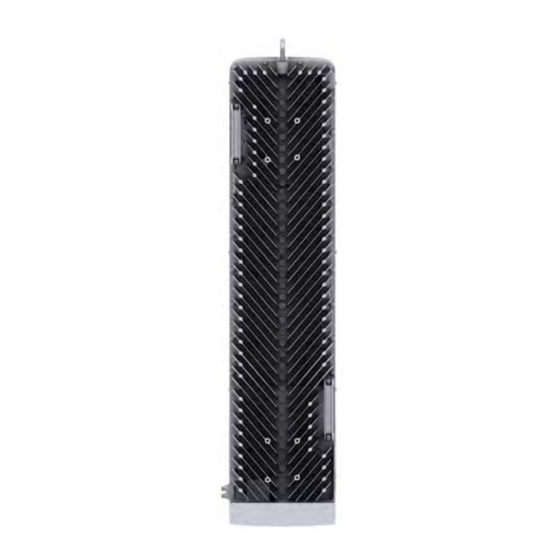
MMU View and External Interface This section provides the physical structure of the MMU and its interfaces. MMU View The figure below depicts the physical structure of the MMU. MT3204 Series Installation Manual v1.0 Copyright © 2018, All Rights Reserved. -
Page 17: Mmu External Interface
[Top View] 9.0 (230) (115) (115) [Left View] [Front View] [Right View] [Rear View] [Bottom View] MMU External Interface The figure below depicts the external interface structure of the MMU. MT3204 Series Installation Manual v1.0 Copyright © 2018, All Rights Reserved. -
Page 18: Figure 2. Mmu External Interface
Confidential Chapter 1 Before Installation Figure 2. MMU External Interface DC_PWR [MMU Bottom View] Ground Terminal MT3204 Series Installation Manual v1.0 Copyright © 2018, All Rights Reserved. -
Page 19: Specifications
Telcordia GR-63-CORE Section 4.4.4 Transportation Vibration Telcordia GR-63-CORE Section 4.4.5 IP rating IP65 FCC part 15 FCC CFR 47 Part 96 Beam Steering Range Horizontal Vertical Safety UL 60950-1 Installation Pole/Wall mounting MT3204 Series Installation Manual v1.0 Copyright © 2018, All Rights Reserved. -
Page 20: Cautions For Installation
When operator installs the MMU, the MMU must be within the protective angle (left/right side 45° each from the central axis) to prevent the MMU from lightning damage. MT3204 Series Installation Manual v1.0 Copyright © 2018, All Rights Reserved. -
Page 21: After Installing
Ensure that the workers do not damage installed cables while cleaning the system. While cleaning the power supply device, take precaution that the device does not come in contact with foreign objects that may cause power failure. MT3204 Series Installation Manual v1.0 Copyright © 2018, All Rights Reserved. -
Page 22: Installation Tools
Tightening M12 hexagonal. bolt Tape Measure 16 ft./150 ft. Measuring length Level Normal Levelling horizontality and verticality Power Extension Cable 100 ft. Basic tool Hammer Drill Normal Wall Type Drilling MT3204 Series Installation Manual v1.0 Copyright © 2018, All Rights Reserved. - Page 23 Industrial Scissor Basic Tool Cutting Knife Basic Tool Cutting Heating Gun 50°C to 300°C Shrinking the feeder cable tube Multi tester Digital Pocket Tester Checking voltage and current to MT3204 Series Installation Manual v1.0 Copyright © 2018, All Rights Reserved.
- Page 24 The required installation tools may vary depending on the site conditions. In addition to the basic tools, protractor, ladder, safety equipment, and cleaning tools must also be arranged, considering the site conditions. MT3204 Series Installation Manual v1.0 Copyright © 2018, All Rights Reserved.
-
Page 25: Chapter 2 Installing System
The figure below depicts the overall procedures for installing the MMU. Figure 3. Procedure to Install the MMU Foundation Work Bringing in Items Unpacking and Transporting Unpacking Items Fixing Unit Bracket Fixing System Fixing Mounting Bracket Fixing MMU MT3204 Series Installation Manual v1.0 Copyright © 2018, All Rights Reserved. -
Page 26: System Arrangement
When fixing a mounting bracket, the length of stud bolts are 8.7 in. (220 mm) for the pole diameter 50~100 A. Pole Size (Diameter) Length of Stud Bolt 50 A, 65 A, 80 A, 90 A, 100 A 8.7 in. (220 mm) MT3204 Series Installation Manual v1.0 Copyright © 2018, All Rights Reserved. -
Page 27: Figure 5. Mmu Arrangement_Wall Type Installation
The dimensions of the front of the MMU change according to the tilt angle, and the maximum dimensions are described in the figure below (MMU Arrangement_ Down Tilting 15°). MT3204 Series Installation Manual v1.0 Copyright © 2018, All Rights Reserved. -
Page 28: Figure 6. Mmu Arrangement_Swivelling
The dimensions of the front of the MMU change according to the tilt angle, and the maximum dimensions are described in the figure below (MMU Arrangement_ Left, Right Swivelling 30°). MT3204 Series Installation Manual v1.0 Copyright © 2018, All Rights Reserved. -
Page 29: Transporting And Unpacking
Unpack the inner packaging after each system is placed on its installation location. Dispose by-products (packaging waste) in accordance with waste management rules. Do not recycle the by-products. MT3204 Series Installation Manual v1.0 Copyright © 2018, All Rights Reserved. -
Page 30: Mmu Handling
Single person lift could cause injury. Get help when moving or lifting. Figure 7. Transporting the MMU [Transporting the Packaging Box] Packaging Box Handle [Transporting the MMU] [MMU Rear] MMU Handle MT3204 Series Installation Manual v1.0 Copyright © 2018, All Rights Reserved. -
Page 31: Fixing Mmu
Check the position for mounting the unit bracket on the back of the MMU and place it in that position. Figure 8. Fixing Unit Bracket (1) Unit Bracket Unit Bracket MMU Rear Side MT3204 Series Installation Manual v1.0 Copyright © 2018, All Rights Reserved. -
Page 32: Fixing Pole Type
Fixing Pole Type This section describes the procedures for fixing the system on the pole. Assembling Pole Mount Bracket-Bottom To assemble the pole mount bracket-bottom for do the following: MT3204 Series Installation Manual v1.0 Copyright © 2018, All Rights Reserved. -
Page 33: Figure 10. Fixing Pole Mount Bracket-Bottom (1)
Pass the stud bolt assembly through the pole mount bracket holes. Figure 10. Fixing Pole Mount Bracket-Bottom (1) Pole Mount Bracket M10 Stud Bolt Assembly Insert the rear bracket into the stud bolt assembly and tighten the fasteners temporarily. MT3204 Series Installation Manual v1.0 Copyright © 2018, All Rights Reserved. -
Page 34: Figure 11. Fixing Pole Mount Bracket-Bottom (2)
When assembling the front bracket and rear 2hole bracket, make sure the up mark is facing upward. Front Bracket Rear 2Hole Bracket Slide the latch of the unit bracket until the lock of the pole-mount bracket assembly is engaged. MT3204 Series Installation Manual v1.0 Copyright © 2018, All Rights Reserved. -
Page 35: Figure 12. Fixing Pole Mount Bracket-Bottom (3)
Rear Bracket 1 EA Fasteners M10 × L220 Stud Bolt Assembly 4 EA M10 Flange Nut 4 EA M10 Hexagon Nut 4 EA Recommended Torque Value M10 Nut 217 lbfin MT3204 Series Installation Manual v1.0 Copyright © 2018, All Rights Reserved. -
Page 36: Figure 13. Fixing Pole Mount Bracket-Top (1)
Pass the stud bolt assembly through the pole mount bracket holes. Figure 13. Fixing Pole Mount Bracket-Top (1) Pole Mount Bracket M10 Stud Bolt Assembly M10 Stud Bolt Assembly Insert the rear 4-hole bracket into the stud bolt. MT3204 Series Installation Manual v1.0 Copyright © 2018, All Rights Reserved. -
Page 37: Figure 14. Fixing Pole Mount Bracket-Top (2)
Stud Bolt Assembly M10 Hex. Nut M10 Flange Nut When assembling the front bracket and rear 4hole bracket, make sure the up mark is facing upward. Front Bracket Rear 4Hole Bracket MT3204 Series Installation Manual v1.0 Copyright © 2018, All Rights Reserved. -
Page 38: Figure 16. Lifting Mmu & Pole Mount Bracket Assembly-Top (1)
Carrying Point_1 Carrying Point_1 Pole Mount Bracket Assembly-Top Carrying Point_1 Rope Figure 17. Lifting MMU & Pole Mount Bracket Assembly-Top (2) Rope Carrying Point_1 Carrying Point_1 Carrying Point_1 Rope MT3204 Series Installation Manual v1.0 Copyright © 2018, All Rights Reserved. -
Page 39: Figure 18. Lifting Mmu & Pole Mount Bracket Assembly-Top (3)
Recommended Torque Value M10 Nut 217 lbfin Working Tools Torque Wrench (100 to 400 lbf·in) Torque Wrench Spanner head (apply hexagonal. head: 17 mm) Spanner (17 mm) MT3204 Series Installation Manual v1.0 Copyright © 2018, All Rights Reserved. -
Page 40: Figure 19. Fixing Pole Mount Bracket Assembly-Top (1)
Fixing Pole Mount Bracket Assembly-Top (2) Pole mount Bracket Assembly-Top Rear 4Hole Bracket Pole Insert the three loosened stud bolt assemblies into the fixing hole of the rear 4- hole bracket. MT3204 Series Installation Manual v1.0 Copyright © 2018, All Rights Reserved. -
Page 41: Figure 21. Fixing Pole Mount Bracket Assembly-Top (3)
Turn it to the left of the plate fixed to the top and bottom of the back of the rear 4hole bracket by rotating them counterclockwise and re-fix the plate. MT3204 Series Installation Manual v1.0 Copyright © 2018, All Rights Reserved. -
Page 42: Figure 23. Fixing Pole Mount Bracket Assembly-Top (5)
When fixing the pole mount bracket assembly-top on a pole, be sure to check the level of bracket. After finishing the installation, you can adjust the level minutely. When occurring poor levelling, adjust the position of fasteners used to fix the pole MT3204 Series Installation Manual v1.0 Copyright © 2018, All Rights Reserved. -
Page 43: Table 6. Parts And Tools For Fixing Mmu On The Pole
Torque Wrench (100 to 400 lbf·in) Torque Wrench Spanner head (apply hexagonal. head: 17 mm) Spanner (17 mm) Hang the unit bracket hook of MMU on the pole mount assembly-top hook’s groove. MT3204 Series Installation Manual v1.0 Copyright © 2018, All Rights Reserved. -
Page 44: Figure 25. Fixing Mmu On The Pole (1)
When the MMU is fixed to the mount bracket assembly, the hooks of the unit brackets must be completely inserted into the fixing grooves of the mount bracket assembly. This ensures that the unit brackets stay intact during vibration or from external influences. MT3204 Series Installation Manual v1.0 Copyright © 2018, All Rights Reserved. -
Page 45: Figure 26. Fixing Mmu On The Pole (2)
Turn it to the left of the plate fixed to the top and bottom of the back of the rear 2hole bracket by rotating them counterclockwise and re-fix the plate. MT3204 Series Installation Manual v1.0 Copyright © 2018, All Rights Reserved. -
Page 46: Fixing Wall Type
This section describes the procedures for fixing the system on the wall. Marking To marking, do the following: Prerequisites Before proceeding with the marking, make sure that you have items mentioned in the following table MT3204 Series Installation Manual v1.0 Copyright © 2018, All Rights Reserved. -
Page 47: Table 7. Tools For Marking
This will reduce marking error range. Check the distance between the location for fixing the MMU and the anchor bolt hole. MT3204 Series Installation Manual v1.0 Copyright © 2018, All Rights Reserved. -
Page 48: Figure 28. Mmu Marking Dimensions
Place a marking paper on the fixing location, and then check the level status using a level and adjust the level of marking paper. If the level status is normal, mark the anchor bolt holes on a wall. MT3204 Series Installation Manual v1.0 Copyright © 2018, All Rights Reserved. -
Page 49: Figure 29. Marking_Wall Mount Bracket-Top Assembly
Anchor Punch (for M12 Set Anchor) Table 9. Anchor Bolt Drill Bits and Hole Depth Category Anchor Bolt Drill Bits Hole Depth Wall Type 0.7 in. (17 mm) 2.2 in. (55 mm) MT3204 Series Installation Manual v1.0 Copyright © 2018, All Rights Reserved. -
Page 50: Figure 30. Drilling & Anchor (1)
Figure 30. Drilling & Anchor (1) Anchor Punch M12 Anchor Anchor Bolt Hole Bolt Hammer Vacuum Cleaner Hammer Drill [Drill Bit] 0.7 in.(17 mm) Fix fasteners to anchor bolt temporarily. MT3204 Series Installation Manual v1.0 Copyright © 2018, All Rights Reserved. -
Page 51: Figure 31. Drilling & Anchor (2)
Torque Wrench Spanner Head (apply hexagonal head: 19 mm) Spanner (19 mm) Hang the mounting bracket-top assembly fixing hole of MMU rear on the anchor bolt fixed to the wall. MT3204 Series Installation Manual v1.0 Copyright © 2018, All Rights Reserved. -
Page 52: Figure 32. Fixing Wall Mount Bracket-Top Assembly (1)
Parts and Tools for Assembling Wall Mount Bracket-Bottom Category Description Parts Wall Mount Bracket Assembly-Bottom 1 EA Slide the latch of the unit bracket until the lock of the wall mount bracket- bottom assembly is engaged. MT3204 Series Installation Manual v1.0 Copyright © 2018, All Rights Reserved. -
Page 53: Figure 34. Assembling Wall Mount Bracket-Bottom
Recommended Torque Value M12 Hexagonal Nut 372 lbfin Working Tools Torque Wrench (100 to 400 lbfin) Torque Wrench Spanner Head (apply hexagonal head: 19 mm) Spanner (19 mm) MT3204 Series Installation Manual v1.0 Copyright © 2018, All Rights Reserved. -
Page 54: Figure 35. Fixing Mmu
By using the RF alignment tool, check the tilt and the azimuth and adjust when there is an issue. For detailed instructions of how to use the RF alignment tool, refer to the user MT3204 Series Installation Manual v1.0 Copyright © 2018, All Rights Reserved. -
Page 55: Mmu Tilting & Swivelling
Torque Wrench Spanner head (apply hexagonal. head: 17 mm) Spanner (17 mm) The MMU tilt angle can be adjusted down from 0 to 15 by 1, and the angle plate is used when tilting. MT3204 Series Installation Manual v1.0 Copyright © 2018, All Rights Reserved. - Page 56 0° Hole MMU Right MMU Right 15° Hole [Tilt 0°] [Tilt 15°] Rotate counterclockwise the fasteners on the mount bracket assembly-bottom at the once or twice to loosen them. MT3204 Series Installation Manual v1.0 Copyright © 2018, All Rights Reserved.
-
Page 57: Figure 36. Mmu Down Tilting (1)
Do not detach the fasteners completely and loosen the 20 mm of the fasteners (number 4) of the angle plate. MT3204 Series Installation Manual v1.0 Copyright © 2018, All Rights Reserved. -
Page 58: Figure 37. Mmu Down Tilting (2)
M10 Hex. Nut [Right View] Angle Plate Fixing Bolt ≒ 20 mm M12 Hex. Nut Angle Plate Remove the angle plate fixing bolt by pushing the angle plate outward. MT3204 Series Installation Manual v1.0 Copyright © 2018, All Rights Reserved. -
Page 59: Figure 38. Mmu Down Tilting (3)
Confidential Chapter 2 Installing System Figure 38. MMU Down Tilting (3) Angle Plate Fixing Bolt Angle Plate [Right View] Adjust the tilt by pulling the MMU forward. MT3204 Series Installation Manual v1.0 Copyright © 2018, All Rights Reserved. -
Page 60: Figure 39. Mmu Down Tilting (4)
MMU Down Tilting (5) Angle Plate Operator B Operator A M10 Hex. Nut Angle Plate Fixing Bolt Angle Plate Fixing Bolt [Right View] Example of 15° Tilting ※ Re-tighten the loosened fasteners. MT3204 Series Installation Manual v1.0 Copyright © 2018, All Rights Reserved. -
Page 61: Figure 41. Mmu Down Tilting (6)
Pole Mount Bracket Assembly-Bottom 1 EA Recommended Torque Value M10 Nut 217 lbfin Working Tools Torque Wrench (100 to 400 lbf·in) Torque Wrench Spanner head (apply hexagonal. head: 17 mm) MT3204 Series Installation Manual v1.0 Copyright © 2018, All Rights Reserved. - Page 62 Loosen the fasteners (M10 hex. nut 2 EA) of the pole mount bracket on the mount bracket assembly-top and remove the stud bolt and sleeve. Remove the front bracket-top from the pole mount bracket-top. MT3204 Series Installation Manual v1.0 Copyright © 2018, All Rights Reserved.
-
Page 63: Figure 42. Bracket Change For Mmu Up Tilting (1)
Loosen the mounting bracket (M10 hex. nut 2 EA) of the pole mount bracket on the mount bracket assembly-bottom and remove the stud bolt and sleeve. Remove the front bracket-bottom from the pole mount bracket-bottom. MT3204 Series Installation Manual v1.0 Copyright © 2018, All Rights Reserved. -
Page 64: Figure 43. Bracket Change For Mmu Up Tilting (2)
Position the front bracket-bottom in line with the fixing hole of the pole mount bracket-top and fix the sleeve and stud bolt with the M10 hex. nut 2 EA. MT3204 Series Installation Manual v1.0 Copyright © 2018, All Rights Reserved. -
Page 65: Figure 44. Bracket Change For Mmu Up Tilting (3)
M10 Hex. Nut The square nut that is fastened to the stud bolt should be positioned so that it is fully inserted into the square hole of the pole mount bracket. MT3204 Series Installation Manual v1.0 Copyright © 2018, All Rights Reserved. - Page 66 Position the front bracket-bottom in line with the fixing hole of the pole mount bracket-bottom and fix the sleeve and stud bolt with the M10 hex. nut 2 EA. MT3204 Series Installation Manual v1.0 Copyright © 2018, All Rights Reserved.
-
Page 67: Figure 45. Bracket Change For Mmu Up Tilting (4)
Assembly-Bottom for Up-Tilting The square nut that is fastened to the stud bolt should be positioned so that it is fully inserted into the square hole of the pole mount bracket. MT3204 Series Installation Manual v1.0 Copyright © 2018, All Rights Reserved. -
Page 68: Figure 46. Bracket Change For Mmu Up Tilting (5)
If the latch of the unit bracket is not fully inserted and fixed, the pole-mount bracket assembly may detach and fall, which can damage the equipment. Ensure that it is fully fixed before proceeding to the next step. MT3204 Series Installation Manual v1.0 Copyright © 2018, All Rights Reserved. -
Page 69: Figure 47. Lifting Mmu & Pole Mount Bracket Assembly-Top (1)
Pole Mount Bracket Assembly-Top for Up-Tilting Carrying Point_1 Carrying Point_2 Rope Figure 48. Lifting MMU & Pole Mount Bracket Assembly-Top (2) Rope Carrying Point_1 Carrying Point_1 Carrying Point_2 Rope MT3204 Series Installation Manual v1.0 Copyright © 2018, All Rights Reserved. -
Page 70: Figure 49. Lifting Mmu & Pole Mount Bracket Assembly-Top (3)
Recommended Torque Value M10 Nut 217 lbfin M4 Screw 13 lbfin Working Tools Torque Wrench (100 to 400 lbf·in) Torque Wrench Spanner head (apply hexagonal. head: 17 mm) MT3204 Series Installation Manual v1.0 Copyright © 2018, All Rights Reserved. -
Page 71: Figure 50. Fixing Pole Mount Bracket Assembly-Top (Up-Tilting) (1)
Place a pole mount bracket assembly-top (up-tilting) to the pole. Figure 51. Fixing Pole Mount Bracket Assembly-Top (Up-Tilting) (2) Pole Mount Bracket Assembly-Top (Up-Tilting) Pole MT3204 Series Installation Manual v1.0 Copyright © 2018, All Rights Reserved. -
Page 72: Figure 52. Fixing Pole Mount Bracket Assembly-Top (Up-Tilting) (3)
Fixing Pole Mount Bracket Assembly-Top (Up-Tilting) (4) Pole M10 Stud Bolt Assembly Rear 4Hole Bracket Pole Mount Bracket Assembly-Top (Up-Tilting) Tighten the flange and the hexagon nuts that are fastened to the stud bolt assembly. MT3204 Series Installation Manual v1.0 Copyright © 2018, All Rights Reserved. -
Page 73: Figure 54. Fixing Pole Mount Bracket Assembly-Top (Up-Tilting) (5)
4hole bracket by rotating them counterclockwise and re-fix the plate. Figure 55. Fixing Pole Mount Bracket Assembly-Top (Up-Tilting) (6) Rear 4Hole Bracket Plate M4 Plate Fixing Screw Do not take the fasteners out completely. MT3204 Series Installation Manual v1.0 Copyright © 2018, All Rights Reserved. -
Page 74: Figure 56. Fixing Pole Mount Bracket Assembly-Top (Up-Tilting) (7)
Torque Wrench Spanner head (apply hexagonal. head: 17 mm) Spanner (17 mm) Torque Driver (6 to 22 lbfin) Screw Driver Bit (‘+’ No.2) Screw Driver (‘+’ No.2) MT3204 Series Installation Manual v1.0 Copyright © 2018, All Rights Reserved. -
Page 75: Figure 57. Fixing Mmu (Up-Tilting) On The Pole (1)
When the MMU is fixed to the mount bracket assembly, the hooks of the unit brackets must be completely inserted into the fixing grooves of the mount bracket assembly. This ensures that the unit brackets stay intact during vibration or from MT3204 Series Installation Manual v1.0 Copyright © 2018, All Rights Reserved. -
Page 76: Figure 58. Fixing Mmu (Up-Tilting) On The Pole (2)
Turn it to the left of the plate fixed to the top and bottom of the back of the rear 4hole bracket by rotating them counterclockwise and re-fix the plate. MT3204 Series Installation Manual v1.0 Copyright © 2018, All Rights Reserved. -
Page 77: Figure 59. Fixing Mmu On The Pole (3)
Recommended Torque Value M10 Hexagon Nut 217 lbfin Working Tools Torque Wrench (100 to 400 lbf·in) Torque Wrench Spanner head (apply hexagonal. head: 17 mm) Spanner (17 mm) MT3204 Series Installation Manual v1.0 Copyright © 2018, All Rights Reserved. - Page 78 MMU Right MMU Right 15° Hole [Tilt 0°] [Tilt 15°] Rotate counterclockwise the fasteners on the pole mount bracket assembly top (up-tilting) at the once or twice to loosen them. MT3204 Series Installation Manual v1.0 Copyright © 2018, All Rights Reserved.
-
Page 79: Figure 60. Mmu Up Tilting (1)
(up-tilting) at the once or twice to loosen them. Do not detach the fasteners completely and loosen the 20 mm of the fasteners (number 4) of the angle plate. MT3204 Series Installation Manual v1.0 Copyright © 2018, All Rights Reserved. -
Page 80: Figure 61. Mmu Up Tilting (2)
M10 Hex. Nut [Right View] Angle Plate Fixing Bolt ≒ 20 mm M12 Hex. Nut Angle Plate Remove the angle plate fixing bolt by pushing the angle plate outward. MT3204 Series Installation Manual v1.0 Copyright © 2018, All Rights Reserved. -
Page 81: Figure 62. Mmu Up Tilting (3)
Confidential Chapter 2 Installing System Figure 62. MMU Up Tilting (3) Angle Plate Fixing Bolt Angle Plate [Right View] Pull the MMU forward to adjust the tilting angle. MT3204 Series Installation Manual v1.0 Copyright © 2018, All Rights Reserved. -
Page 82: Figure 63. Mmu Up Tilting (4)
Tighten the loosened fastening material of the mounting bracket assembly- top/-bottom for tilting up (follow the order 1 to 3 indicated in the figure above), and then fix them. MT3204 Series Installation Manual v1.0 Copyright © 2018, All Rights Reserved. -
Page 83: Figure 65. Mmu Up Tilting (6)
For detailed instructions of how to use the RF alignment tool, refer to the user manual per each manufacturer. Swiveling The MMU swivel angle can be adjusted left/right from 0 to 30. MT3204 Series Installation Manual v1.0 Copyright © 2018, All Rights Reserved. -
Page 84: Table 18. Tools For Swiveling Mmu
Torque Wrench Spanner head (apply hexagonal. head: 17 mm) Spanner (17 mm) Loosen the MMU by turning M10 hexagon nut of mounting bracket two or three times counterclockwise. (Do not separate it completely.) MT3204 Series Installation Manual v1.0 Copyright © 2018, All Rights Reserved. -
Page 85: Figure 66. Mmu Swiveling Adjustment (1)
Figure 66. MMU Swiveling Adjustment (1) Wall Mount Bracket Assembly-Top M10 Hex. Nut Wall Mount Bracket Assembly-Bottom M10 Hex. Nut Pull the MMU left/right to adjust the swiveling angle. MT3204 Series Installation Manual v1.0 Copyright © 2018, All Rights Reserved. -
Page 86: Figure 67. Mmu Swiveling Adjustment (2)
Confidential Chapter 2 Installing System Figure 67. MMU Swiveling Adjustment (2) [Left Swiveling 30° Example] Fix the M10 hex. nut of mount bracket-top/bottom assembly. MT3204 Series Installation Manual v1.0 Copyright © 2018, All Rights Reserved. -
Page 87: Figure 68. Mmu Swiveling Adjustment (3)
By using the RF alignment tool, check the tilt and the azimuth and adjust when there is an issue. For detailed instructions of how to use the RF alignment tool, refer to the user manual per each manufacturer. MT3204 Series Installation Manual v1.0 Copyright © 2018, All Rights Reserved. -
Page 88: Chapter 3 Connecting Cables
The figure below depicts the procedure to connect system cables: Figure 69. Procedure to Connect System Cable Grounding Connecting Ground Cable Connecting Power Cable Power Cabling Connecting CRPI Cable Interface Cable Connection Connecting UDA Cable MT3204 Series Installation Manual v1.0 Copyright © 2018, All Rights Reserved. -
Page 89: Guidelines For Cable Connections
To inspect the cable path, ensure the following. A minimum cable length must be selected, so that the length does not affect the cable installation and maintenance. MT3204 Series Installation Manual v1.0 Copyright © 2018, All Rights Reserved. -
Page 90: Cable Cutting
Install the DC power cable and the data transmission cable away from the AC power cable to prevent electromagnetic induction. The table below outlines the recommended minimum allowed cable bend radius for different types of cables: MT3204 Series Installation Manual v1.0 Copyright © 2018, All Rights Reserved. -
Page 91: Cable Binding
Connect each cable of the connector assembly in a straight line. Be careful when connecting the cable so that contact failure does not occur at the connector connection due to tension. MT3204 Series Installation Manual v1.0 Copyright © 2018, All Rights Reserved. -
Page 92: Identification Tag Attachment
Install the DC power cable and the data transmission cable away from the AC power cable to prevent electromagnetic induction. Ensure the work is done by personnel properly trained for the cabling job. MT3204 Series Installation Manual v1.0 Copyright © 2018, All Rights Reserved. -
Page 93: Cabling Diagram
The inlet hole finishing method of external equipment must be done after consultation with operation company, if the cable is connected to external equipment, such as optical distribution box. - Cables: Power cable, CPRI cables, and UDA cable MT3204 Series Installation Manual v1.0 Copyright © 2018, All Rights Reserved. -
Page 94: Grounding
Checking MGB specifications per site and preparing connecting parts 6 AWG, 2 Hole, Hole diameter: 1/4 in. (6.4 mm), Hole spacing: 0.6 in. (16 mm) Fastener Checking MGB specifications per site and preparing connecting parts MT3204 Series Installation Manual v1.0 Copyright © 2018, All Rights Reserved. -
Page 95: Figure 72. Connecting Ground Cable (1)
Assemble a pressure terminal and a heat shrink tube at the end of the MMU ground cable. Align the pressure terminal to the mounting hole of the MMU ground terminal. Firmly fix the pressure terminal onto the MMU ground terminal using MT3204 Series Installation Manual v1.0 Copyright © 2018, All Rights Reserved. -
Page 96: Figure 73. Connecting Ground Cable (2)
Chapter 3 Connecting Cables fasteners. Figure 73. Connecting Ground Cable (2) M6 SEMS (Hex. +) MMU Ground Terminal Pressure Terminal M6 SEMS (Hex. +) Heat Shrink Tube Ground Cable [MMU] MT3204 Series Installation Manual v1.0 Copyright © 2018, All Rights Reserved. -
Page 97: Power Cabling
Note, however, that the maximum installation length is based on the conditions under which each cable is normally installed and that it may change if the conditions change. MT3204 Series Installation Manual v1.0 Copyright © 2018, All Rights Reserved. -
Page 98: Connecting Power Cable
The table below outlines the power cable connector pin map: Table 23. DC Power Cable/Connector Pin Map Power Connector Pin Number Description Color Pin 1 -48 V DC Pin 2 Black MT3204 Series Installation Manual v1.0 Copyright © 2018, All Rights Reserved. -
Page 99: Figure 75. Connecting Power Cable (1)
Install the power cable from the distributor to the MMU. Figure 75. Connecting Power Cable (1) [MMU Bottom View] DC Power Cable DC Distributor Separate the cap from the MMU side and cable side connector. MT3204 Series Installation Manual v1.0 Copyright © 2018, All Rights Reserved. -
Page 100: Figure 76. Connecting Power Cable (2)
Insert the connector aligning white dot of the cable side connector and white dot of the system side connector. When inserting the connector, push the shell to upper side. MT3204 Series Installation Manual v1.0 Copyright © 2018, All Rights Reserved. -
Page 101: Figure 77. Connecting Power Cable (3)
The method for connecting or disconnecting the power connector is as follows: - For connecting the connector, push the shell to upper side. - For disconnecting the connector, pull the coupling nut to lower side. MT3204 Series Installation Manual v1.0 Copyright © 2018, All Rights Reserved. - Page 102 Confidential Chapter 3 Connecting Cables Coupling Nut Push Pull Shell [Connector 연결] [Connector 분리] MT3204 Series Installation Manual v1.0 Copyright © 2018, All Rights Reserved.
-
Page 103: Interface Cable Connection
When the optical module is detached without using the dedicated tool, the optical module may be jammed and the handle may be damaged due to a lack of opening capacity of the minimum necessary handle. MT3204 Series Installation Manual v1.0 Copyright © 2018, All Rights Reserved. -
Page 104: Optical Module Removal (3)
Inset the optical module's bail, facing the front of the system, to the port. System System Rear Side Rear Side Optical Module Bail Do not inset when the optical module's bail is unlocked. MT3204 Series Installation Manual v1.0 Copyright © 2018, All Rights Reserved. -
Page 105: Table 24. Parts And Tools For Connecting Cpri Cable
- Make sure to clean the connector in accordance with the cleaning directions in Annex. - Do not touch the ferrule at the end of optical cable because it is easy to be damaged. MT3204 Series Installation Manual v1.0 Copyright © 2018, All Rights Reserved. -
Page 106: Connecting Cpri Cable (1)
Separate the cap from the system side connector (L0 port). Figure 83. Connecting CPRI Cable (2) Cap (L0 Port) The method for connecting/disconnecting the cap (push-pull type) is as follows: MT3204 Series Installation Manual v1.0 Copyright © 2018, All Rights Reserved. -
Page 107: Connecting Cpri Cable (3)
Before connecting the CPRI cable connector, the Ferrule of the connecter of cable side should be cleaned first by using the optical connector cleaner. (Appendix B for more information.) MT3204 Series Installation Manual v1.0 Copyright © 2018, All Rights Reserved. -
Page 108: Connecting Cpri Cable (4)
Connecting CPRI Cable (5) System side’s optical module DLC Plug When the connector is fastened tight, the white line on the system side connector should be invisible (or hidden). MT3204 Series Installation Manual v1.0 Copyright © 2018, All Rights Reserved. -
Page 109: Table 25. Parts And Tools For Connecting Uda Cable
Operation: 5 × OD Installation: 10 × OD Connector External alarm device Check specifications of external device output terminal per site and prepare fasteners. JONHON, Push Pull Type, RJ45MF-CT-07 MT3204 Series Installation Manual v1.0 Copyright © 2018, All Rights Reserved. -
Page 110: Connecting Uda Cable (1)
Install the UDA cable from the external alarm device to the MMU. Figure 87. Connecting UDA Cable (1) [MMU Bottom View] UDA Cable External Alarm Device Separate the cap from the MMU side and cable side connector. MT3204 Series Installation Manual v1.0 Copyright © 2018, All Rights Reserved. -
Page 111: Connecting Uda Cable (2)
The latch of cable side connector should be toward the front of the MMU. Figure 89. Connecting UDA Cable (3) Front Side Rear Side RJ45 Plug Latch Cable side connector’s white dot MT3204 Series Installation Manual v1.0 Copyright © 2018, All Rights Reserved. -
Page 112: Figure 90. Connecting Uda Cable (4)
The method for connecting or disconnecting the backhaul (RJ45) connector is as follows: - For connecting the connector, push the shell to upper side. - For disconnecting the connector, pull the coupling nut to lower side. MT3204 Series Installation Manual v1.0 Copyright © 2018, All Rights Reserved. - Page 113 Confidential Chapter 3 Connecting Cables Coupling Nut Pull Push Shell MT3204 Series Installation Manual v1.0 Copyright © 2018, All Rights Reserved.
-
Page 114: Figure 91. Installation Inspection Procedure
Sharing the Results of Corrective Actions and Preparing Preventive Plan Inspection Plan Create an inspection sheet per system and select an inspector to set an inspection schedule per site. MT3204 Series Installation Manual v1.0 Copyright © 2018, All Rights Reserved. -
Page 115: Table 27. Construction Situation Checklist
Compliance with fastening torque value Insulation status Checking electrical contact between insulators (insulation resistance tester) Azimuth & Tilt Checking the tilt result is right. Grounding Installation of ground bar Checking the separation of MT3204 Series Installation Manual v1.0 Copyright © 2018, All Rights Reserved. - Page 116 Checking compliance with fastening torque value Installation status of cable Position Marking content Checking tag installation method Other data Cable specification Checking the specification cables Cabling Cable damage MT3204 Series Installation Manual v1.0 Copyright © 2018, All Rights Reserved.
- Page 117 Cable tray and duct Checking installation status Status of inside/outside of Checking the stocking condition (waste the equipment and system parts, waste materials, and packing surrounding area materials) Opinion ■ MT3204 Series Installation Manual v1.0 Copyright © 2018, All Rights Reserved.
- Page 118 Citizen Broadband Radio Service Direct Current Downlink Massive MIMO Unit Main Ground Bar Return SELV Safe Extra Low Voltage SEMS pre-asSEMbled washers and screws S-FTP Screened-Foiled Twisted Pair Uplink MT3204 Series Installation Manual v1.0 Copyright © 2018, All Rights Reserved.
- Page 119 Follow the manufacturer's instructions for cleaning the optical connectors. Measure the Optical Output and Connecting the Optical Connector To measure the optical output Using an optical power meter check the optical output. MT3204 Series Installation Manual v1.0 Copyright © 2018, All Rights Reserved.
- Page 120 If the measurement result does not meet the reference value, discard the cable, replace it with a new cable, and then clean the new one and connect it to the system. [LC/PC Plug] [Optical Power meter] MT3204 Series Installation Manual v1.0 Copyright © 2018, All Rights Reserved.
-
Page 121: Table 28. Standard Torque Value For Fastening Bolts
The torque values can be different, defending on the material, characteristic, and specification of the equipment and fastener. Ensure that you check the proper torque value for each specification of the equipment and the fastener. MT3204 Series Installation Manual v1.0 Copyright © 2018, All Rights Reserved. - Page 122 MT3204 Series Installation Manual Document Version 1.0 © 2018 Samsung Electronics Co., Ltd. All rights reserved.
Need help?
Do you have a question about the MT3204 Series and is the answer not in the manual?
Questions and answers