Table of Contents
Advertisement
Quick Links
Warranty, Service & Repair
To register your product with the manufacturer, fill out the enclosed
warranty card and return it immediately to:
Flowline Inc.
10500 Humbolt Street
Los Alamitos, CA 90720.
If for some reason your product must be returned for factory service,
contact Flowline Inc. to receive a Material Return Authorization
number (MRA) first, providing the following information:
1. Part Number, Serial Number
2. Name and telephone number of someone who can answer
technical questions related to the product and its application.
3. Return Shipping Address
4. Brief Description of the Symptom
5. Brief Description of the Application
Once you have received a Material Return Authorization number,
ship the product prepaid in its original packing to:
Flowline Factory Service
MRA _____
10500 Humbolt Street
Los Alamitos, CA 90720
To avoid delays in processing your repair, write the MRA on the
shipping label. Please include the information about the malfunc-
tion with your product. This information enables our service tech-
nicians to process your repair order as quickly as possible.
WARRANTY
Flowline warrants to the original purchaser of its products that such
products will be free from defects in material and workmanship under
normal use and service for a period which is equal to the shorter of
one year from the date of purchase of such products or two years from
the date of manufacture of such products.
This warranty covers only those components of the products which
are non-moving and not subject to normal wear. Moreover, products
which are modified or altered, and electrical cables which are cut to
length during installation are not covered by this warranty.
Flowline's obligation under this warranty is solely and exclusively
limited to the repair or replacement, at Flowline's option, of the prod-
ucts (or components thereof) which Flowline's examination proves to
its satisfaction to be defective. FLOWLINE SHALL HAVE NO
OBLIGATION FOR CONSEQUENTIAL DAMAGES TO PERSON-
AL OR REAL PROPERTY, OR FOR INJURY TO ANY PERSON.
This warranty does not apply to products which have been subject to
Electrical or chemical damage due to improper use, accident, negli-
gence, abuse or misuse. Abuse shall be assumed when indicated by
electrical damage to relays, reed switches or other components. The
warranty does not apply to products which are damaged during ship-
ment back to Flowline's factory or designated service center or are
returned without the original casing on the products. Moreover, this
warranty becomes immediately null and void if anyone other than ser-
vice personnel authorized by Flowline attempts to repair the defective
products.
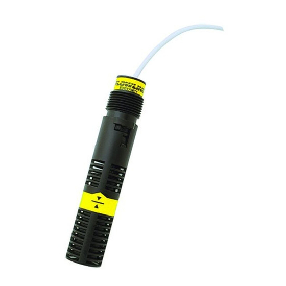
Vertical Buoyancy
Level Switch
LV10 Series
Owner's Manual
Version 3.0A
© 1999 FLOWLINE Inc.
All rights reserved.
Manual # LV900001
Products which are thought to be defective must be shipped prepaid
and insured to Flowline's factory or a designated service center (the
identity and address of which will be provided upon request) within
30 days of the discovery of the defect. Such defective products must
be accompanied by proof of the date of purchase.
Flowline further reserves the right to unilaterally wave this warranty
and to dispose of any product returned to Flowline where:
a. There is evidence of a potentially hazardous material present
with product.
b. The product has remained unclaimed at Flowline for longer than
30 days after dutifully requesting disposition of the product.
THERE ARE NO WARRANTIES WHICH EXTEND BEYOND
THE DESCRIPTION ON THE FACE OF THIS WARRANTY. This
warranty and the obligations and liabilities of Flowline under it are
exclusive and instead of, and the original purchaser hereby waives, all
other remedies, warranties, guarantees or liabilities, express or
implied. EXCLUDED FROM THIS WARRANTY IS THE IMPLIED
WARRANTY OF FITNESS OF THE PRODUCTS FOR A PARTIC-
ULAR PURPOSE OR USE AND THE IMPLIED WARRANTY OF
MERCHANT ABILITY OF THE PRODUCTS.
This warranty may not be extended, altered or varied except by a writ-
ten instrument signed by a duly-authorized officer of Flowline, Inc.
File Name: Flowline_LevelSwitch_LV10_om_D599
5/99
®
Advertisement
Table of Contents

Related Manuals for FlowLine LV10 Series


Summary of Contents for FlowLine LV10 Series
- Page 1 Flowline’s obligation under this warranty is solely and exclusively 30 days after dutifully requesting disposition of the product. limited to the repair or replacement, at Flowline’s option, of the prod- ucts (or components thereof) which Flowline’s examination proves to THERE ARE NO WARRANTIES WHICH EXTEND BEYOND its satisfaction to be defective.
-
Page 2: Specifications
SPECIFICATIONS Step One Accuracy: ± 2 mm in water Technology Repeatability: ± 1 mm in water The vertical buoyancy switch and the vertical float switch both con- Extreme orientation: ± 20° from vertical sist of a float, magnet, reed switch and baffle body which dampens Specific gravity: .8 minimum turbulence and eliminates the negative effects of switch chatter. -
Page 3: Safety Precautions
Doing so will activate the internal reed switch. Temperature and Pressure: The LV10 series switch is designed for use in application tempera- tures up to 90 °C, and for use at pressures up to 25 psi (2 bar) @ 25 °C., derated @ 1.667 psi (.113 bar) per °C. - Page 4 LV10 switch. Cable Length: Determine the length of cable required between the LV10 series sen- sor and its point of termination. Allow enough slack to ensure the easy installation, removal and/or maintenance of the sensor. The cable length may be extended up to a maximum of 1000 feet, using a well- insulated, 18 gauge shielded wire.
- Page 5 WIRING ORIENTATION Step Six Step Seven All Models: Vertical Buoyancy Level Switch (LV10-_3_1): Wiring to a FLOWLINE Controller The LV10-_3_1 switch can be wired normally open or normally LC10 Series Controller closed for your application requirement. Normally Open: WHITE Use the Black and White wires for operating the LV10-_3_1 in a nor- BLACK mally open state.
- Page 6 ORIENTATION MAINTENANCE Step Eight Step Nine Vertical Float Level Switch (LV10-_2_1): General: The LV10-_2_1 switch can be wired normally open or normally While a filter shroud protects the float from particulate contamina- closed for your application requirement. tion, the switch may need to be cleaned periodically too prevent jam- ming or sticking.
Need help?
Do you have a question about the LV10 Series and is the answer not in the manual?
Questions and answers