
Related Manuals for HBM U15 Series


Summary of Contents for HBM U15 Series
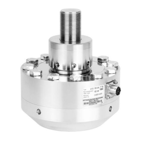
- Page 1 Mounting Instructions Montageanleitung Force transducer Kraftaufnehmer A2100-4.0 en/de...
- Page 2 English ..........Seite 3 - 29 Deutsch .
-
Page 3: Table Of Contents
Contents Page English Safety instructions ..........Scope of supply . -
Page 4: Safety Instructions
Safety instructions Intended use The U15 force transducer is to be used exclusively for force measurement tasks and directly related control tasks. Use for any additional purpose shall be deemed to be not as intended. In the interests of safety, the transducer should only be operated as described in the Mounting Instructions. - Page 5 The CE mark enables the manufacturer to guarantee that the product complies with the requirements of the relevant EC directives (the Declaration of Conformity can be found at http://www.hbm.com/HBMdoc). Conversions and Modifications The transducer must not be modified from the design or safety engineering point of view except with our express agreement.
- Page 6 Qualified personnel This device must only be installed by qualified personnel, strictly in accordance with the specifications and in conjunction with the safety requirements and regulations listed below. It is also essential to observe the appropriate legal and safety regulations for the application concerned. The same applies to the use of accessories.
-
Page 7: Scope Of Supply
Scope of supply • U15 force transducer (version‐dependent) • U15 operating manual Accessories (not included in scope of supply): • Cables/plugs Order number 1-KAB157-3 Connection cable with bayonet locking; IP67; 3 m long, 6.5 mm; TPE outer Ø sheath; 6 x 0.25 mm ;... -
Page 8: Application Notes
Application notes Two mechanical versions are available for force transducers of the U15 type series: Double bridge Single bridge The transducers are suitable for measuring tensile and compressive forces. Because they provide highly accurate static force measurements, they must be handled very carefully. Particular care must be taken when transporting and installing the devices. - Page 9 CAUTION The flange screws and the tensile adapter are permanently moun ted onto the transducer and must not be loosened; otherwise the specifications may deviate from the guaranteed values and the ca libration. A2100-4.0 en/de...
-
Page 10: Conditions On Site
Conditions on site The transducer is not suitable for use in nuclear power stations or for continuous exposure to seawater. 3.1 Ambient temperature The temperature effects on the zero signal and on the sensitivity are compensated. To obtain optimum measurement results, the nominal (rated) temperature range must be observed. -
Page 11: Mechanical Installation
• Welding currents must not be allowed to flow over the transducer. If there is a risk that this might happen, you must use a suitable low‐ohm connection to electrically bypass the transducer. HBM, for example, provides the highly flexible EEK ground cable, which can be screwed on, both above and below the transducer. -
Page 12: Mounting Accessories For Compressive Loading
4.3 Mounting accessories for compressive loading Thrust pieces according to ISO 376 are available for introducing comprerssive forces. They can be mounted directly onto the threaded spherical pin. Thrust piece Transducer Thrust piece Type Order no. U15/2,5kN-50kN 1-EDO4/20kN U15/100kN-250kN 1-U15/250kN/EDO U15/500kN 1-U15/500kN/EDO U15/1MN... -
Page 13: Mounting Accessories For Tensile Loading
4.4 Mounting accessories for tensile loading Knuckle eyes and tensile force application parts (ZKM) to ISO 376 are avail able for installing the U15. These mounting aids prevent the introduction into the transducer of torsional moment and, where 2 knuckle eyes are used, bending moment, as well as lateral and oblique loads. - Page 14 Installing tensile force application parts: • Screw the ZKM force application part thread into the transducer thread until the stop is reached and then screw it one and a half turns back out. ZKM tensile force application part to ISO 376 ØD Type Order no.
-
Page 15: Electrical Connection
• The shield can be accessed via a cut in the cable sheath • Connect the shield extensively to the housing ground. Connecting to a plug: Connect the cable shield extensively to the connector housing. To extend the cabling, we recommend shielded pairs of HBM low‐capacitance measurement cables. A2100-4.0 en/de... -
Page 16: Pin Assignment
Fig. 5.1: The cable shield is connected in accordance with the Greenline concept (see http://www.hbm.com/Greenline). This encloses the measurement system in a Faraday cage, so that it is not affected by electromagnetic interference. When connecting plugs to cables with free ends, the shielding must be connected extensively. -
Page 17: Teds Transducer Identification
The basis for this is a 1‐wire EEPROM DS2433, made by Maxim/Dallas. HBM provides you with the TEDS Editor for storing your data. This is a component part of the MGCplus Setup Assistant software (see the TEDS operating manual ”TEDS data memory in the transducer” on the Internet at www.hbm.com/TEDS). - Page 18 - a short comment in text form, - filter settings, - zero value. Example: Content written by HBM, on the basis of the individual test certificate: Area 3 of the U15/5kN sensor with identification no. 123456, made by HBM on 1.6.2006. Template: Bridge Sensor...
- Page 19 ”Full Precision”, ”mV/V” and ”uV/V” for the accuracy of the characteristic transducer curve mapped in TEDS. HBM always opts for ”Full Precision” here, in order to be able to use full digital resolution. This choice is also recommended to users who program the TEDS memory themselves.
-
Page 20: Versions And Order Numbers
Versions and order numbers Code Measuring range 2k50 2.5 kN 5k00 5 kN 10k0 10 kN 25k0 25 kN 50k0 50 kN 100k 100 kN 250k 250 kN 500k 500 kN 1M00 1 MN Number Plug version Plug version of mea- Transducer Plug suring... -
Page 21: Specifications
Specifications Type Data as per VDI 2638 and ISO 376 Nominal (rated) force Class under ISO 376 (0.2 F to F Nominal (rated) mV/V sensitivity relative sensitivity deviation <"0.1 relative deviation from <"1 zero mV/V Relative reproducibility and repeatability errors (0.2F to F ) for:... - Page 22 Operating range of the excitation voltage 0.5 to 12 Nominal (rated) °C temperature range +10 to +40 t,nom Operating temperature °C range -30 to +85 Storage temperature °C range -30 to +85 °C Reference temperature Max. operating force Breaking force Limit torque N⋅m 155 180 635 1320 2855...
-
Page 23: Dimensions
Dimensions ØA ØB ‐ Second plug for the Bayonet: plug compatible with an double bridge version MIL-C-26482 series 1 connection Option: ‐ U15/2.5 kN ... 50 kN ØF Thread: plug compatible with an MIL-C-26482 series 1 connection R (Ball) U15/100 kN ... 1 MN ØH R (Ball) ØP... -
Page 24: Mounting Dimensions Of The Connection Variants
8.1 Mounting dimensions of the connection variants KAB 157-3 ‐ plug compatible with an MIL-C-26482 series 1 connection Fig. 8.1: Reserved additional space for the bayonet locking connecting plug KAB 158-3 ‐ plug compatible with an MIL-C-26482 series 1 connection Fig. -
Page 25: Accessories
8.2 Accessories ZGOW / ZGIM Order no. A j B j D Type knuckle eye U15/2,5kN- 1-Z4/20kN/ 0.23 50kN ZGOW U15/100kN- 1-ZGIM33F 115 140 201.5 28 M33x2 45 250kN U15/500kN 1-ZGIM42F 126 162 36 M42x2 61 U15/1MN 1-ZGIM72F 190 220 50 M72x2 100 110 A2100-4.0 en/de... - Page 26 ZGUW / ZGAM center of bearing Order no. Type knuckle eye U15/2,5kN- 1-Z4/20kN/ 41.7 16 67.7 88,7 50kN ZGUW U15/100kN- 1-ZGAM33F 115 118 182,5 M33x2 250kN U15/500kN 1-ZGAM42F 126 134 M42x2 U15/1MN 1-ZGAM72F 190 178 M72x2 12.6 A2100-4.0 en/de...
- Page 27 Thrust piece per ISO 376 ∅ ∅ B -0.1 α Weight Order no. j A j B app. Thrust piece (kg) U15/2,5kN-50kN 1-EDO4/20kN 0.34 16.2 U15/100kN-250kN 1-U15/250kN/EDO 33.2 U15/500kN 1-U15/500kN/EDO 42.2 U15/1MN 1-EDO4/500kN 72.4 112 68 A2100-4.0 en/de...
- Page 28 Tensile force application parts per ISO 376 Type U15/2,5kN-50kN; Order no. 1-Z4/20kN/ZKM M20x1.5 Ø20 Ø16 Ø25 M20x1.5 Type U15/100kN-250kN; Order no. 1-U15/250kN/ZKM M33x2 M30x2 Ø30 M30x2 M33x2 A2100-4.0 en/de...
- Page 29 Type U15/500kN; Order no. 1-U15/500kN/ZKM M56x4 M42x2 M56x4 M42x2 Type U15/1MN; Order no. 1-U15/1MN/ZKM M72x2 M64x4 Ø64 M64x4 M72x2 A2100-4.0 en/de...
- Page 30 A2100-4.0 en/de...
- Page 31 Inhalt Seite Deutsch Sicherheitshinweise ..........Lieferumfang .
-
Page 32: Sicherheitshinweise
Sicherheitshinweise Bestimmungsgemäßer Gebrauch Der Kraftaufnehmer U15 ist ausschließlich für Kraftmessaufgaben und direkt damit verbundene Steuerungsaufgaben zu verwenden. Jeder darüber hinaus gehende Gebrauch gilt als nicht bestimmungsgemäß. Zur Gewährleistung eines sicheren Betriebes darf der Aufnehmer nur nach den Angaben in der Montageanleitung verwendet werden. Bei der Verwen dung sind zusätzlich die für den jeweiligen Anwendungsfall erforderlichen Rechts‐... - Page 33 Bedeutung: CE‐Kennzeichnung Mit der CE‐Kennzeichnung garantiert der Hersteller, dass sein Produkt den Anforderungen der relevanten EG‐Richtlinien entspricht (die Konformitätser klärung finden Sie unter http://www.hbm.com/HBMdoc). Umbauten und Veränderungen Der Aufnehmer darf ohne unsere ausdrückliche Zustimmung weder konstruk tiv noch sicherheitstechnisch verändert werden. Jede Veränderung schließt eine Haftung unsererseits für daraus resultierende Schäden aus.
- Page 34 lich die für den jeweiligen Anwendungsfall erforderlichen Rechts‐ und Sicher heitsvorschriften zu beachten. Sinngemäß gilt dies auch bei Verwendung von Zubehör. Qualifiziertes Personal sind Personen, die mit Aufstellung, Montage, Inbe triebsetzung und Betrieb des Produktes vertraut sind und die über die ihrer Tätigkeit entsprechende Qualifikationen verfügen.
-
Page 35: Lieferumfang
Lieferumfang • Kraftaufnehmer U15 (je nach Ausführung) • Bedienungsanleitung U15 Zubehör (nicht im Lieferumfang enthalten): Bestellnummer K-CAL-FD... DKD‐Kalibrierschein nach ISO 376 1-KAB157-3 Anschlusskabel mit Bajonettverschluss; IP67; 3 m lang, 6,5 mm; Ø Außenmantel TPE; 6 x 0,25 mm ; freie Enden, geschirmt 1-KAB158-3 Anschlusskabel mit Schraubverschluss;... -
Page 36: Anwendungshinweise
Anwendungshinweise Die Kraftaufnehmer der Typenreihe U15 sind in zwei Ausführungen erhältlich: Doppelbrücke Einfachbrücke Die Aufnehmer sind für Messungen von Zug‐ und Druckkräften geeignet. Sie messen statische Kräfte mit hoher Genauigkeit und verlangen daher eine um sichtige Handhabung. Besondere Aufmerksamkeit erfordern hierbei Transport und Einbau der Geräte. - Page 37 VORSICHT Die Flanschschrauben und der Zugadapter sind fest mit dem Auf nehmer verbunden und dürfen nicht gelöst werden; andernfalls können die technischen Daten von den garantierten Werten und der Kalibrierung abweichen. A2100-4.0 en/de...
-
Page 38: Bedingungen Am Einsatzort
Bedingungen am Einsatzort Für den Einsatz in Kernkraftwerken sowie für den Dauerkontakt mit See wasser ist der Aufnehmer nicht geeignet. 3.1 Umgebungstemperatur Die Temperatureinflüsse auf das Nullsignal sowie auf den Kennwert sind kom pensiert. Um optimale Messergebnisse zu erzielen, ist der Nenntemperatur bereich einzuhalten. -
Page 39: Mechanischer Einbau
• Es dürfen keine Schweißströme über den Aufnehmer fließen. Sollte diese Gefahr bestehen, so müssen Sie den Aufnehmer mit einer geeigneten niederohmigen Verbindung elektrisch überbrücken. Hierzu bietet z. B. HBM das hochflexible Erdungskabel EEK an, das oberhalb und unterhalb des Aufnehmers angeschraubt wird. -
Page 40: Einbauhilfen Für Druckbelastung
4.3 Einbauhilfen für Druckbelastung Zur Einleitung von Druckkräften stehen Druckstücke nach ISO 376 zur Verfü gung. Diese können direkt auf den balligen Gewindezapfen gesetzt weren. Druckstück Aufnehmer Druckstück Bestellnummer U15/2,5kN-50kN 1-EDO4/20kN U15/100kN-250kN 1-U15/250kN/EDO U15/500kN 1-U15/500kN/EDO U15/1MN 1-EDO4/500kN A2100-4.0 en/de... -
Page 41: Einbauhilfen Für Zugbelastung
4.4 Einbauhilfen für Zugbelastung Zum Einbau der U15 stehen Gelenkösen und Zugkrafteinleitungen (ZKM) nach ISO 376 zur Verfügung. Diese Einbauhilfen verhindern die Einleitung von Torsionsmomenten und bei Verwendung von 2 Gelenkösen auch von Bie gemomenten sowie Quer‐ und Schrägbelastungen in die Aufnehmer. Sie sind nur für statische Zugbelastungen des Aufnehmers vorgesehen. - Page 42 Einbau von Zugkrafteinleitungen: • Drehen Sie das Gewinde des Krafteinleitungsteils ZKM bis zum Anschlag in das Gewinde des Aufnehmers ein und danach eine anderthalbe Umdre hungen wieder heraus. Zugkrafteinleitung ZKM nach ISO 376 ØD Bestellnummer U15/2,5kN-50kN 1-Z4/20kN/ZKM ca. 372 ca. 277 ca.
-
Page 43: Elektrischer Anschluss
Anschliessen an einen Stecker: Den Kabelschirm flächig auf das Steckergehäuse legen. Für die Kabelverlängerung empfehlen wir paarweise geschirmtes, kapazitäts armes Messkabel von HBM. 5.2 Anschlussbelegung Die Aufnehmer sind mit folgenden elektrischen Anschlüssen erhältlich: • Bajonettanschluss: steckkompatibel zu Anschluss MIL-C-26482 Serie 1 oder •... -
Page 44: Aufnehmer-Identifikation Teds
Am Anschluss E (gegen Masse an PIN D) steht ein digitales Identifikationssy stem zur Verfügung. Basis ist ein 1-Wire EEPROM DS2433 der Fa. Maxim/ Dallas. Zum Einspeichern der Daten stellt HBM den TEDS‐Editor zur Verfügung. Dieser ist Bestandteil der Software MGCplus‐Setup‐Assistent (siehe TEDS‐ A2100-4.0 en/de... - Page 45 - der Aufnehmerart, - der Messgröße, - des elektrischen Ausgangssignals, - der erforderlichen Speisung. Für den Kraftaufnehmer U15 hat HBM bereits das Template Bridge Sensor beschrieben. Weitere Templates wie z.B. das Template Signal Conditioning können vom Anwender zusätzlich beschrieben werden.
- Page 46 Beispiel: Von HBM auf Basis des individuellen Prüfprotokolls beschriebener Inhalt: Be reich 3 des Sensors U15/5kN mit der Ident‐Nr. 123456, hergestellt am 1.6.2006 bei HBM. Template: Bridge Sensor Parameter Wert Einheit Ändern erfor dert Erklärung Rechte Stufe : Transducer Electrical...
- Page 47 ”mV/V” und ”uV/V” für die Genauigkeit der in TEDS abgebildeten Aufnehmer kennlinie zu wählen. HBM wählt hier stets ”Full Precision” um die volle digitale Auflösung nutzen zu können. Diese Wahl wird auch Anwendern empfohlen, die den TEDS- Speicher selbst programmieren.
-
Page 48: Ausführungen Und Bestellnummern
Ausführungen und Bestellnummern Code Nennkraft 2k50 2,5 kN 5k00 5 kN 10k0 10 kN 25k0 25 kN 50k0 50 kN 100k 100 kN 250k 250 kN 500k 500 kN 1M00 1 MN Mess Steckerausführung Steckerausführung Aufnehmer Stecker brücken identifikation schutz anzahl Brücke A Brücke B... -
Page 49: Technische Daten
Technische Daten Angaben gemäß VDI 2638 und ISO 376 Nennkraft Klasse nach ISO 376 (0,2 F bis F Nennkennwert mV/V rel. Kennwertabwei chung <"0,1 rel. Abweichung des Nullsignals <"1 Rel. Spannweite (0,2F bis F ) bei: unveränderter Einbau stellung <"0,025 verschiedenen Ein... - Page 50 Gebrauchsbereich der Speisespannung 0,5 bis 12 °C Nenntemperaturbereich B +10 bis +40 t,nom Gebrauchstemperatur °C bereich -30 bis +85 Lagerungstemperatur °C bereich -30 bis +85 °C Referenztemperatur Max. Gebrauchskraft Bruchkraft Grenzdrehmoment N⋅m 155 180 635 1320 2855 5715 Nennmessweg 0,04 0,06 0,08 0,12...
-
Page 51: Abmessungen
Abmessungen ØA ØB Bajonett: steckkompatibel zu 2. Stecker bei Doppel Anschluss MIL-C-26482 Serie 1 brücken‐Version Optional: U15/2,5 kN ... 50 kN Gewinde: steckkompatibel zu ØF Anschluss MIL-C-26482 Serie 1 R (Kugel) U15/100 kN ... 1 MN ØH R (Kugel) ØP ØK Nenn... -
Page 52: Einbaumaße Der Anschlussvarianten
8.1 Einbaumaße der Anschlussvarianten KAB 157-3 steckkompatibel zu Anschluss MIL-C-26482 Serie 1 Abb. 8.1: Bauraum für Anschlussstecker Bajonettverschluss KAB 158-3 steckkompatibel zu Anschluss MIL-C-26482 Serie 1 Abb. 8.2: Bauraum für Anschlussstecker Schraubverschluss A2100-4.0 en/de... -
Page 53: Zubehör
8.2 Zubehör ZGOW / ZGIM Bestell Nr. A j B j D SW W V Gelenköse U15/2,5kN- 1-Z4/20kN/ 21 - 0,23 50kN ZGOW U15/100kN- 1-ZGIM33F 39 140 201,5 28 M33x2 35 4 250kN U15/500kN 1-ZGIM42F 55 36 M42x2 44 5 U15/1MN 1-ZGIM72F 90 50 M72x2 100 110 60 7... - Page 54 ZGUW / ZGAM Bestell Nr. Gelenköse ZGUW U15/2,5kN- 1-Z4/20kN/ZGUW 41,7 16 42 67,7 88,7 21 15 50kN U15/100kN- 1-ZGAM33F 115 118 182,5 M33x2 35 28 250kN U15/500kN 1-ZGAM42F 60 126 134 M42x2 44 36 U15/1MN 1-ZGAM72F 90 190 178 M72x2 60 50 12,6 A2100-4.0 en/de...
- Page 55 Druckstück nach ISO 376 ∅ ∅ B -0.1 α Druckstück Gewicht j A j B Bestellnummer ca. (kg) U15/2,5kN-50kN 1-EDO4/20kN 0,34 16,2 U15/100kN-250kN 1-U15/250kN/EDO 33,2 U15/500kN 1-U15/500kN/EDO 42,2 U15/1MN 1-EDO4/500kN 72,4 112 68 A2100-4.0 en/de...
- Page 56 Zugkrafteinleitung nach ISO 376 Typ U15/2,5kN-50kN; Bestellnummer 1-Z4/20kN/ZKM M20x1,5 Ø20 Ø16 Ø25 M20x1,5 Typ U15/100kN-250kN; Bestellnummer 1-U15/250kN/ZKM M33x2 M30x2 Ø30 M30x2 M33x2 A2100-4.0 en/de...
- Page 57 Typ U15/500kN; Bestellnummer 1-U15/500kN/ZKM M56x4 M42x2 M56x4 M42x2 Typ U15/1MN; Bestellnummer 1-U15/1MN/ZKM M72x2 M64x4 Ø64 M64x4 M72x2 A2100-4.0 en/de...
- Page 58 A2100-4.0 en/de...
- Page 60 Form. Sie stellen keine Beschaffenheits- oder Haltbarkeits- garantie im Sinne des §443 BGB dar und begründen keine Haftung. Hottinger Baldwin Messtechnik GmbH Im Tiefen See 45 S 64293 Darmstadt S Germany Tel. +49 6151 803-0 S Fax: +49 6151 803-9100 Email: info@hbm.com www.hbm.com...
Need help?
Do you have a question about the U15 Series and is the answer not in the manual?
Questions and answers