Table of Contents
Advertisement
LEYBOLD VACUUM
Vacuum Solutions
Application Support
Service
GA 05.141/6.02
digital
MAG
Series
MAG W 830 C
MAG W 1300 C
MAG 1500 CT
MAG W 1500 C, CT
MAG W 2200 C
MAG W 2800 C, CT
MAG W 3200 CT
Turbomolecular Pump
with Magnetic Bearing
digital
MAG.DRIVE
Electronic Frequency
Converter
Operating Instructions
Advertisement
Table of Contents

Related Manuals for Leybold vacuum MAG digital Series


Summary of Contents for Leybold vacuum MAG digital Series
- Page 1 LEYBOLD VACUUM Vacuum Solutions Application Support Service GA 05.141/6.02 digital Series MAG W 830 C MAG W 1300 C MAG 1500 CT MAG W 1500 C, CT MAG W 2200 C MAG W 2800 C, CT MAG W 3200 CT...
-
Page 2: Table Of Contents
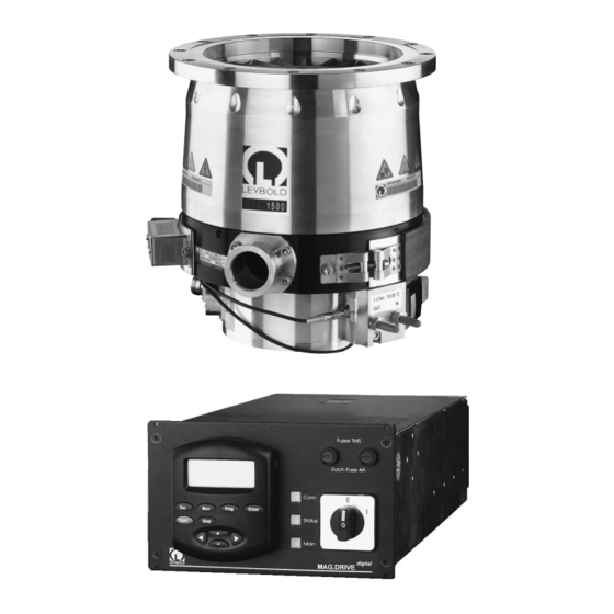
Contents Page Troubleshooting......70 Description ......4 Warning messages . - Page 3 Description MAG 1500 CT MAG W 1500 C MAG W 830 C MAG W 1500 CT MAG W 1300 C MAG W 2200 C MAG W 2800 CT MAG W 3200 CT Fig. 1 MAG turbopumps GA 05.141/6.02 - 07/2003...
-
Page 4: Description
Description Each Fuse 4 A digital digital Fig. 2 MAG.DRIVE Front panel 1 Description 1.1 System overview digital The Leybold MAG pumping system consists of: • The MAG.DRIVE frequency converter • The MAG turbopump; see Figure 1 The electronic converter converts the single-phase line supply voltage into a three-phase DC voltage to The MAG are turbomolecular pumps utilizing magne- drive the pump motor. -
Page 5: Compatibility With Pumped Media
Description 1.2 Compatibility with Sublimation Some media (e.g. AlCl ) can sublimate in the pump and pumped media form deposits. Thick coatings can infringe on the requi- red operating clearence and ultimately cause the pump The MAG are specifically designed for the needs of the to seize. -
Page 6: Contents
Description 1.3 Design of the MAG 1.4 Function and design of digital the MAG.DRIVE The MAG comprises basically the pump housing, the multistage rotor with the stator package, the drive, and a digital The MAG.DRIVE electronic converter is used to magnetic bearing. - Page 7 Description Standard rotor Wide range rotor Fig. 3 Section of a MAG GA 05.141/6.02 - 07/2003...
-
Page 8: Standard Specification
Description 1.5 Standard specification Front panel Main switch 9-pin connecting socket for the plug-in control or for The turbomolecular pumps are shipped complete, connection of a serial interface sealed in a PE bag containing a desiccant. 2 short-stroke keys The maximum effective life time of the desiccant is one 1 green/red STATUS LED year. - Page 9 Description Each Fuse 4 A digital digital MAG.DRIVE Each Fuse 4 A Prog Enter Start Stop digital digital MAG.DRIVE with plug-in control Fig. 4 Front panel X14 Connection control plug X19 Mains connection X20 Connection magnetic (X22) bearing / pump motor / memory chip X21 Connection TMS / purge gas valve...
-
Page 10: Technical Data
Description 1.6 Technical data W 830 C W 1300 C W 1300 C DN 160 DN 200 DN 250 Pumping speed (PNEUROP) for N l·s 1100 1220 for Ar l·s 1050 1180 for H l·s 1020 Compression for N > 5·10 >... - Page 11 Description Technical data (continued) 1500 C/CT W 1500 C/CT 1500 C/CT W 1500 C/CT DN 200 DN 200 DN 250 DN 250 Pumping speed (PNEUROP) for N l·s 1100 1100 1220 1220 for Ar l·s 1000 1050 1180 1180 for H l·s 1020 1020...
- Page 12 Description Technical data (continued) W 2200 C W 2200 C W 2800 CT W 3200 CT W 3200 CT DN 200 DN 250 DN 250 DN 320 VG 350 JIS Pumping Speed for N l·s 1600 2000 2650 3200 3200 for Ar l·s 1450...
-
Page 13: Purge Gas
Description 3500 With purge gas MAG W 3200 DN 320 with splinter guard Forepump 100 m Pipe 1 m DN 40 3000 according to PNEUROP MAG W 2800 DN 250 2500 MAG W 2200 DN 250 2000 MAG W 2200 DN 200 1500 MAG (W) 1300 / 1500 DN 250 1000... - Page 14 Description GA 05.141/6.02 - 07/2003...
-
Page 15: Pump Configuration
Description 1.7 Ordering data Part No. Pumps see Table “Pump configuration” Seal Kit DN 160/200/250 standard on request Seal Kit DN 250 metal 200 07 901 Seal Kit DN 320 standard on request Seal Kit DN 350 JIS standard on request digital MAG.DRIVE converter... - Page 16 Description 0° 0° 90° 270° 90° DRIVE/BEARING connection connection DRIVE/BEARING connection 225° 180° 180° Cable DRIVE/BEARING Cable Converter cable outlet Pump cable outlet length DRIVE/BEARING X20 DRIVE/BEARING X23 PK X24 Part No. —————————————————————————————————————————— 1.5 m bended 225° straight straight 400036V0001 1.5 m straight straight...
- Page 17 Description max. 115 straight plugs bended plugs Ø 3.3 Each Fuse 4 A 122.4 digital Fig. 8 Dimensional drawing of the MAG.DRIVE ; dimensions in mm t u s S t a 19“ installation frame I V E 4 x M3 screws digital Fig.
- Page 18 Description MAG W 830 C MAG W 1300 C Inlet flange A Forevacuum connection —————————————————————————————————————————————— MAG W 830 C 160 ISO-F 225 15° 45° DN 40 KF MAG W 1300 C 200 ISO-F 285 15° 30° DN 40 KF / DN 25 KF MAG W 1300 C 250 ISO-F 335 15°...
- Page 19 Description MAG W 1500 C Inlet flange ———————————————— 200 ISO-F 250 ISO-F Ø262 DN 40 KF Ø175 164.5 Fig. 11 MAG 1500 C, Dimensions in mm GA 05.141/6.02 - 07/2003...
- Page 20 Description MAG (W) 1500 CT Ø A Ø B Ø C Inlet flange ——————————————————————————— 200 ISO-F 30° 15° 250 ISO-F 30° 15° 200 CF 15° 7.5° 200 JIS 45° 22.5 307 Ø 262 DN 40 KF 164.5 Ø175 M8, 15 mm deep Fig.
- Page 21 Description MAG W 2200 C Inlet flange ——————————————————— 200 ISO-F 250 ISO-F Ø 317 DN 40 164.6 Ø 199 Fig. 13 MAG W 2200 C, Dimensions in mm GA 05.141/6.02 - 07/2003...
- Page 22 Description MAG W 2800 CT, MAG W 3200 CT Inlet flange ———————————————————————————————— 250 ISO-F 320 ISO-F 13.5 350 JIS Ø 369 DN 40 196.5 Fig. 14 MAG 2800 CT and MAG 3200 CT, Dimensions in mm GA 05.141/6.02 - 07/2003...
-
Page 23: Installation
Installation 2 Installation Warning General safety information Unauthorized opening of the converter Warning voids the warranty. Before opening the converter, always dis- Indicates procedures that must be strictly observed to connect it from the mains and the pump! prevent hazards to persons. Before disconnecting any cables make sure Caution that the converter is switched off and the... -
Page 24: Unpacking - Storing - Transportation
Installation 1 Aluminum cover 2 Screws Fig. 15 Removing the transport seal 2.3 Operating environment 2.2 Unpacking - storing - transportation When using the MAG inside a magnetic field, the magnetic induction at the pump housing must not ex- Remove the equipment from the transportation box and ceed 5 mT;... - Page 25 Installation MAG W 830 C Intake flange Forevacuum flange connection DRIVE/BEARING Purge gas in connection Cooling water connection Correct 17 mm 35 mm Wrong Caution 8 bolts M10 x 35 Install the splinter guard as shown. Installation torque per bolt: 35 Installing the splinter guard upside Bolt quality:12.9 according to DIN 898 with coating down may lead to contact between...
- Page 26 Installation MAG W 1300 C Intake flange Forevacuum flange connection DRIVE/BEARING Purge gas in connection Cooling water connection Correct DN 200: 260 mm DN 250: 310 mm DN 200: 213 mm DN 250: 261 mm 14 mm Wrong 35 mm Caution 12 bolts M10 x 35 Install the splinter guard as shown.
- Page 27 Installation MAG W 1500 C Intake flange Forevacuum flange Purge gas valve Cooling water connection Purge gas in DRIVE/BEARING connection connection connection Correct DN 200: 260 mm DN 250: 310 mm DN 200: 213 mm DN 250: 261 mm 14 mm Wrong 35 mm Caution...
- Page 28 Installation MAG (W) 1500 CT with DN 200/250 ISO-F Intake flange Heater Forevacuum flange Purge gas valve Cooling water connection Purge gas in DRIVE/BEARING connection connection connection Correct DN 200: 260 mm DN 250: 310 mm DN 200: 213 mm DN 250: 261 mm 14 mm Wrong...
- Page 29 Installation MAG W 1500 CT with CF and JIS intake flange Intake flange Heater Forevacuum flange Purge gas valve Cooling water connection Purge gas in DRIVE/BEARING connection connection connection DN 200 CF DN 200 JIS Correct 10 mm 2 mm 40 mm Wrong 17 mm...
- Page 30 Installation MAG W 2200 C Intake flange Forevacuum flange DRIVE/BEARING connection Cooling water connection PK connection Purge gas in DN 200: 260 mm DN 250: 310 mm 1 Housing 2 Splinter guard 3 Ring DN 200: 213 mm DN 250: 261 mm 14 mm 35 mm 12 bolts M10 x 35...
- Page 31 Installation MAG W 2800 C, CT Intake flange Heater Forevacuum flange Purge gas valve Purge gas in Cooling water connection DRIVE/BEARING connection connection connection 310 mm 1 Housing 2 Splinter guard 3 Ring 261 mm 15.5 mm 35 mm 12 bolts M10 x 35 Installation torque per bolt: 35 Bolt quality:12.9 according to DIN 898 with coating 0,2% yield strength >...
- Page 32 Installation MAG W 3200 CT with DN 320 ISO-F Intake flange Heater Forevacuum flange Purge gas valve Purge gas in Cooling water connection DRIVE/BEARING connection connection connection 395 mm 1 Housing 2 Splinter guard 3 Ring 318 mm 14 mm 40 mm 10 bolts M12 x 40 Installation torque per bolt: 45...
- Page 33 Installation MAG W 3200 CT with VG 350 JIS Intake flange Heater Forevacuum flange Purge gas valve Purge gas in Cooling water connection DRIVE/BEARING connection connection connection 420 mm 1 Housing 2 Splinter guard 3 Ring 318 mm 17.5 mm 40 mm 10 bolts M12 x 40 Installation torque per bolt: 45...
-
Page 34: Connecting The Mag To The Vacuum Chamber
Installation M = 30,000 to M = 30,000 to 65,000 Nm 65,000 Nm Correct Wrong Fig. 25 Vacuum chamber fixed to the floor 2.4 Connecting the MAG to Warning The pump must be securely attached. If the the vacuum chamber pump should suddenly seize, inadequate attachment could cause the pump to break The MAG is shipped in a sealed PE bag with desiccant. - Page 35 Installation Key to Fig. 22 Turbomolecular pump Forevacuum gauge point Backing pump Anti-vibration bellows Forevacuum valve High vacuum valve Purge gas connection Valve in the roughing line Electronic frequency converter — — — — roughing line; recommended if shorter cycle times are to be achieved —...
-
Page 36: Connecting The Backing Pump
Installation M < 150 Nm < 150 Nm Fig. 27 Maximum torques for the forevacuum connection 2.5 Connecting the backing Connect the forevacuum flange of the MAG to the backing pump. pump The torque on the forevacuum connection flange must not exceed the values shown in Fig. - Page 37 Installation MAG (W) 1500, 2800, 3200 Ø 1/4“ (6.4 mm) Cooling water Cooling water Do not mix up the inlet and the outlet! MAG W 1300 C Swagelock tube 1/4“ John Guest fitting for hoses 6 mm outer dia. MAG W 830 C MAG W 2200 C Stainless steel Swagelock tube fitting...
- Page 38 Installation Operation window °C Temperature MAG (W) 1500/2800/3200 CT: Bypass operation All pumps: Cooling Differential pressure between inlet and outlet Fig. 29 Recommended cooling water flow GA 05.141/6.02 - 07/2003...
-
Page 39: Connecting The Cooling Water
Installation Pump cooling Bypass Fig. 30 Schematic of the cooling water flow for MAG (W) 1500, 2800, 3200 CT 2.6 Connecting the cooling Connect the cooling water to the connectors; see Fig. 28. water Caution for CT versions Cooling water specifications The CT versions have a cooling water by- 10 - 30 °C Inlet temperature... -
Page 40: Connecting The Purge Gas
Installation 2.7 Connecting the purge gas With no voltage applied the purge gas and vent valve is closed. Please contact Leybold for assistance in making the The purge gas and vent valve will be open when swit- decision as to which media can be pumped with or with- digital ching on the MAG.DRIVE . - Page 41 Installation upper magnetic bearing Motor lower magnetic lower magnetic bearing bearing 24 V Sensor PVW 2,4 Fig. 31 Purge gas and vent valve assembly and turbomolecular pump (schematic) Purge gas Choke (capillary) Venting gas To purge gas inlet of MAG W 830 and MAG W 1300 Fig.
-
Page 42: Installing The Mag.drive Digital
Installation 2.8 Installing the Warning Unauthorized opening of the converter digital MAG.DRIVE voids the warranty. Hazardous voltages are present inside the The converter can be installed in a 19” cabinet. It is 1/2 converter. Death or severe injury can occur of 19“... -
Page 43: Control Plug X14
Installation 1 2 3 EMERGENCY OFF X14.47 EMERGENCY OFF active EMERGENCY OFF X14.48 1 = Phase L 2 = Not assigned 3 = Neutral N S = PE Fig. 33 Connector assignment X19, supply connection Fig. 34 Control plug X14: Emergency off Connect the converter (X21) to the TMS connection Relay outputs (X30) using the TMS cable. - Page 44 Installation Pumps with TMS DRIVE/BEARING MAINS Control plug Pumps without TMS DRIVE/BEARING MAINS Control plug Pumps with optional purge vent valve DRIVE/BEARING Purge Vent Purge/Vent MAINS Control plug Fig. 35 Block wiring diagram GA 05.141/6.02 - 07/2003...
-
Page 45: Interface Connector
Installation X14 50 pole Sub-D I/O PIN SIGNAL Relay 1 n.o. FAILURE 18 Relay 1 com. FAILURE 34 Relay 1 n.c. FAILURE Relay 2 n.o. NORMAL 19 Relay 2 com. NORMAL 35 Relay 2 n.c. NORMAL OPERATION OPERATION OPERATION Relay 3 n.o. WARNING 20 Relay 3 com. - Page 46 Installation Relay 1 Failure X14.18 No failure X14.1 X14.34 Start command applied Relay 2 Normal Operation & X14.19 Actual frequency X14.2 Normal operation X14.35 Relay 3 Warning Warning X14.20 X14.3 X14.36 Relay 4 Acceleration Acceleration X14.21 X14.4 X14.37 Relay 5 Deceleration Deceleration X14.22 X14.5...
- Page 47 Installation Motor- or bearing- temperature Threshold Motor current Function Threshold signal relay Act. frequency Relay 6/7/8/9 Option Threshold X14.23/24/25/26 No cooling water No purge gas X14.6/7/8/9 TMS temp. o.k. X14.39/40/41/42 Venting Pump standstill Start command Power supply o.k. Function analog output Scale Analog output Rotor displacement...
-
Page 48: Operation
Operation 3 Operation 3.1 General operation rules Venting The magnetic bearing in the MAG are immune to wear. As to suitable gases, see Chapter 2.7. In addition to the magnetic bearings, the MAG is equip- Venting Method ped with touch-down bearings which protect the rotor against mechanical contact with the stator if the pump is The pump must be vented via the purge gas and ven- subjected to external shock loading or when the pump is... - Page 49 Operation Forevacuum pressure/mbar Time/s Fig. 40 Curve for safe venting of the MAG; pressure rise as a function of venting time GA 05.141/6.02 - 07/2003...
-
Page 50: Operation With The Start And Stop Keys
Operation 3.2 Operation with the Significance of the lamps START and STOP keys (green) Is lit if communication has been established via the Switching on interface. digital • Switch on the MAG.DRIVE STATUS (green/red) The MAIN LED lights green. Red, steady light = Failure If the pump has the optional TMS (including e.g. -
Page 51: Remote Control
Operation +15 V ~ 3 kOhm X14.48 Shutdown X14.47 X14.11 Operating mode: REMOTE 0 V = 0 Programming only via 15 V = 1 X14.12 serial interface START Start delay time X14.10 START interface START & pump START key pad STOP key pad ≥1... -
Page 52: Plug-In Control
Plug-in control 4 Plug-in control 4.1 Operation with plug-in Switching off control digital The MAG.DRIVE controls the venting automatically provided purge gas is connected to the MAG and the digital MAG.DRIVE is programmed correspondingly (“Vent Observe the general operation rules given on”). - Page 53 Plug-in control Function • Returns to the operating display from the storage procedure without storage. • Returns to the operating display from any point of the basic menu. Acceleration • No function 14.5A 254Hz HOK Prog • Selects the programming menu from the operating display. •...
-
Page 54: Operating Statuses
Plug-in control 4.2 Operating statuses Overload The speed is continuously monitored and controlled. If Switch-On Guard the speed, even at maximum current, cannot be held at the setpoint, as a result of external influences, e.g. The converter goes into the “Switch On Guard” operating excessive gas intake, the speed reduces until the con- status after the power is switched on and after initializa- verter goes into the “Overload”... - Page 55 Plug-in control Mains switched on Initialization Switch On Guard After a failure, quit a second time Ready START command STOP command Start Delay Mains ok Mains failure Acceleration Frequency > P 25 x P24 Mains failure Mains Down Normal Operation Frequency >...
-
Page 56: Operating Menu
Plug-in control 4.3 Operating menu 4.3.1 Basic Menu Menu item Description Adjustable value / option cess min. max. stan- Unit value value dard Ready Operating display Ready 0.0 A 0 Hz Enter Freq. Setpoint Sets the speed for operation r/w on Freq. -
Page 57: Menu System Info
Plug-in control 4.3.2 Menu System Info Menu item Description Adjustable value / option cess min. max. Unit value value fault Real-Time Clock Real-Time Clock actual value System Info 99.12.31 23:59 Format: YY.MM.DD HH:MM Greenwich-Mean-Time (GMT) Enter Reference-Time for false memory Real-Time Clock 99.12.31 23:59 Product Name... -
Page 58: Menu Failure Storage
Plug-in control 4.3.3 Menu Failure Storage Menu item Description Adjustable value / option cess min. max. Unit value value fault Failure Storage Failure Total No. of total failures since actual value 65535 manufacturing date Enter Failure Total Failure TMS No. of TMS-Failures since actual value 65535 65535... -
Page 59: Menu Set Converter
Plug-in control 4.3.4 Menu Set Converter Menu item Description Adjustable value / option Set Converter cess min. max. stan- Unit Enter value value dard Relay 6 Option Relay 6 Option Relay with change-over contact; r/w on Bearing Temp. the operator can select one of Motor Current the functions described in Table A Frequency... - Page 60 Plug-in control Table A “Option relays” Function of the option relays Refer to Set Converter/Relay option (section 4.3.4). There are 4 option relays (relay 6...9) with change-over contact; the operator can select one of the functions descri- bed in the following table. If the condition of the selected functions is performed, the selected relay switches over.
-
Page 61: Menu Set Pump
Plug-in control 4.3.5 Menu Set Pump Menu item Description Adjustable value / option Set Pump cess min. max. stan- Unit Enter value value dard Normal Operation 95 % Normal Operation Threshold for normal operation corresponding to the r/w off Enter frequency setpoint Max. -
Page 62: Total View Of The Menu
Plug-in control 4.3.8 Total view of the menu Basic menu Ready Failure Storage System Info 0.0 A 0 Hz Enter Enter Enter Freq. Setpoint Failure Total Real-Time Clock 600 Hz 65535 99.12.31 23:59 Enter Enter Enter Failure TMS Motor Temp. 50 °C Product Name 65535... - Page 63 Plug-in control Programming menu Set Converter Set TMS Set Purge/Vent Set Pump Enter Enter Enter Enter Relay 6 Option Purge/Vent Normal Operation TMS Setpoint 70 °C Purge OFF Bearing Temp. 95 % Purge ON Motor Current Enter Enter Via X14 Frequency Max.
-
Page 64: Temperature Management System
Plug-in control 4.4 Temperature Heat up The setpoint temperature will be reached within 30 to 60 Management System minutes depending on cooling and environmental condi- tions. For temperature sensitive applications observe the Function description cooling water specifications (refer to Section 1.6 and 2.6). -
Page 65: Power Control System (Pcs)
Plug-in control T +5 K T +2 K T +1 K T set T –1 K T –5 K TMS Code 3 4 3 6 4 6 Heater ON Cooling ON Warning Signal TMS OK digital Fig. 46 Typical function diagram TMS for the MAG.DRIVE 4.5 Power control system (PCS) (only for MAG (W) 1500, 2200, 2800, 3200) -
Page 66: Maintenance
Maintenance 5 Maintenance 5.1 Cleaning 5.4 Cleaning the frequency converter internally If required clean the turbomolecular pump and the fre- quency converter of dust with a dry cloth. Depending on the installation site the converter may collect grime (dust, moisture) on the inside. Such conta- mination may lead to malfunctions, overheating or short circuits. - Page 67 Maintenance ring nut (2x) aluminum cover plastic adhesive film washer (6x) screw (6x) nut (4x) plastic cap plastic adhesive film dry cartridge Cap screw with O ring Fig. 47 Sealing the MAG tightly GA 05.141/6.02 - 07/2003...
-
Page 68: Service At Leybold's
Maintenance Proceed as follows to seal the turbomolecular pump Cover the forevacuum connection port with its plastic immediately after removing it from your process. cap. Purge the pump for two hours with the backing pump Seal the high-vacuum connection flange with the cover running. - Page 69 Maintenance bolts collar flange retaining ring blank flange Centering ring with O-ring desiccant clamping ring blank flange screw cap with O ring polyethylene bag with cable tie Fig. 48 Sealing the MAG tightly with the metal seal kit GA 05.141/6.02 - 07/2003...
-
Page 70: Troubleshooting
Troubleshooting 6 Troubleshooting In case of a malfunction, the MAG will be braked and the Warning first line of the display shows The MAG shall be stopped completely and FAILURE the mains power cord detached before you digital open the MAG.DRIVE . - Page 71 Troubleshooting Warning Message on Display Possible Cause Measures Unbalanc. PVW13 Mechanical shocks, perhaps due to tool If warning message persists contact Leybold Unbalanc. PVW24 maintenance. service. Unbalanc. PZ12 Shock venting. Check the chamber pressure during operati- A rotor displacement excee- ding the warning threshold Converter failure.
-
Page 72: Failure Messages
Troubleshooting 6.2 Failure messages Failure Message on Display Possible Cause Measures Motor Temp. Motor temperature exceeds the failu- Acknowledge failure message. re threshold e.g. due to a high gas Temperature sensor inside Take the actual motor temperature reading from the load. - Page 73 Troubleshooting Failure Message on Display Possible Cause Measures Mechanical shocks, possibly due to tool Acknowledge failure message and restart MB, Purge ON maintenance. the pump. If failure message persists MB, Purge OFF contact Leybold service. An abnormal displacement Shock venting. Check the chamber pressure during the ot the rotor occured at fre- operation.
- Page 74 Troubleshooting TMS temperature sensor Pt 100 Cooling water temperrature sensor Pt 100 typical resistance 70 to 75 Ω Heater plug X31 Pin 1 and 3 of the temperature sensors Fig. 49 Temperature sensors Failure Message on Display Possible Cause Measures Bearing Temp.
- Page 75 Troubleshooting Failure Message on Display Possible Cause Measures TMS 1 Fuse TMS blown. Step 1: Check fuse The converter measures a Replace fuse TMS (F4A, 5x20 mm) if blown. heating current of less than Heating element or internal pump Step 2: Check pump (heating element X31) 300 mA when heater is on.
- Page 76 Troubleshooting Failure Message on Display Possible Cause Measures Bearing Temp. open Pt 100 (temperature sensor bearing) Check pump (temperature sensor). For measures damaged. see failure Bearing Temp. Sensor loop is interrupted Cooling Temp. open Pt 100 (temperature sensor cooling) Check cable conections. is not connected.
-
Page 77: Malfunctions
Troubleshooting 6.3 Malfunctions Malfunction Possible Cause Measures Converter dead, LED No power supply. Check the line voltage. “mains” does not light up Fuse F1 blown or converter failure. Contact Leybold service. after switching on. Display malfunction, confu- Converter failure. Switch the converter off and on again. If the sing messages. -
Page 78: Eec Manufacturer's Declaration
EEC Manufacturer’s Declaration in the sense of EEC Directive on Machinery 89/392/EWG, Annex IIb We - Leybold Vakuum GmbH - herewith declare that Applied harmonized standards: operation of the incomplete machine defined below, is • EN 292 Part 1 & 2 Nov. -
Page 79: Declaration Of Conformity
Declaration of Conformity as defined by the EMC guideline 89/336/EWG with revisions 91/263/EWG and 93/68/EWG RIR-MAG.DRIVE-EMV digital Product: MAG.DRIVE 2000-12-07 We herewith declare sole responsibility for the product meet the requirements outlined in the EG requirements on 89/336/ EWG (EMC guideline) with revisions 91/263/EWG and 1. -
Page 80: Declaration Of Conformity
Declaration of Conformity as per EG Low-Voltage Guidelines 73/23/EWG, Attachment lll B RIR-MAG.DRIVE-NSR digital Product: MAG.DRIVE 2000-12-07 We herewith declare sole responsibility for the product including the required accessories, as agreeing with EG guide- lines 72/23/EWG, and 93/68/EWG. 1. Product: Frequency converter 2. - Page 81 The system MAG 1500 • turbomolecular pump • connecting cables • frequency converter has been tested by the TUV Rheinland of North America according to the requirements of • NRTL (used standard UL 3101-1/10.93) • Semi S2-0200 used standards: SEMI S2-0200 UL 3111 / UL 3101 EU Low Voltage Directive EU Machinery Directive...
- Page 82 Declaration of Contamination of Vacuum Equipment and Components The repair and/or service of vacuum equipment and components will only be carried out if a correctly completed declaration has been submitted. Non-completion will result in delay. The manufacturer could refuse to accept any equipment without a declara- tion.
- Page 83 Process Gas: Was the turbopump replaced? Yes; If yes, replacement pump P/N: replacement pump S/N: Date Installed: Date Removed: Date Received: Date Examined: Examined by: Received Condition: Findings: Cause of Failure: Recommendations: Remarks/Questions: LEYBOLD VACUUM LEYBOLD VACUUM GA 05.141/6.02 - 07/2003...
-
Page 84: Operating Instructions For Mag Digital Series
digital Operating Instructions for MAG series Operating Instructions Valid for pumps Valid for Converters digital GA 05.141/1.02 MAG 1500 C, CT MAG.DRIVE MAG W 1500 C, CT English Pumping speed curves, (February 2000) dimensional drawing and preliminary troubleshooting incomplete digital GA 05.141/2.02 MAG 1500 C, CT MAG.DRIVE...
Need help?
Do you have a question about the MAG digital Series and is the answer not in the manual?
Questions and answers