
Related Manuals for Leybold vacuum TRIVAC B Series


Summary of Contents for Leybold vacuum TRIVAC B Series
-
Page 1: Operating Instructions
OPERATING INSTRUCTIONS GA01201_1002 TRIVAC ® D 4 B / D 8 B Rotary Vane Vacuum Pump Cat. No. 113 08/17 140 081/082 vacuum... -
Page 2: Table Of Contents
Contents Section Page Important Safety Information ........6 Description . - Page 3 Contents Section Page Maintenance ..........21 Checking the Oil Level .
- Page 4 Notes Leybold Service If a pump is returned to Leybold indicate whether the pump is free of sub- stances damaging to health or whether it is contaminated. If it is contaminated also indicate the nature of the hazard. Leybold must return any pumps without a “Declaration of Contamination”...
- Page 5 Should you have any questions relating to safety, operation or maintenance of the equip- ment, please get in touch with your nearest Leybold Vacuum office. The icon indicates procedures that must be strictly observed to prevent Warning hazards to persons.
-
Page 6: Important Safety Information
Safety information Important Safety Information ■ Before beginning with any maintenance or service work on the Warning Non-compliance with the follo- TRIVAC B, disconnect the pump from all power supplies. wing precautions can result in ■ Do not operate the pump with any of the covers removed. severe injury! Serious injury may result. - Page 7 Safety information ■ It is recommended to always operate the TRIVAC B with a suitable exhaust line which is properly connected. It must slope down and away from the pump. ■ When moving the TRIVAC B always use the allowed means only. The pump is equipped as standard with a handle.
-
Page 8: Description
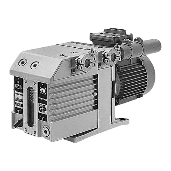
Description Key to Fig. 1 Oil filter OF 4-25 Exhaust filter AF 4-8 Condensate trap AK 4-8 Fig. 1 TRIVAC B with accessories Description TRIVAC B pumps are oil-sealed rotary vane pumps. The TRIVAC D 4 B and D 8 B are dual-stage pumps. The number in the type designation (4 or 8) indicates the pumping speed in m ·... -
Page 9: Function
Description Key to Fig. 2 Intake port Inlet screen Anti-suckback valve Intake channel Vane Pump chamber Rotor Cover plate, connection for inert gas ballast Exhaust channel 10 Exhaust valve 11 Internal demister 12 Spring buckles 13 Cover plate, connection for oil filter Fig. - Page 10 Description The gas ballast valve is opened (position I) and closed (position 0) by tur- ning the gas ballast knob (7/5) on the front. Lubrication system To enable the TRIVAC B to be used at intake pressures as high as 1,000 mbar, a special lubricating system was developed featuring force-lubricati- on of the sliding bearings.
-
Page 11: Supplied Equipment
Description Key to Fig. 3 Accessories Bearings Non-return valve Pump chamber of the TRIVAC Oil reservoir Oil pump Fig. 3 Schematic of the lubricating system Key to Fig. 4 Oil reservoir 5 Valve seat Spring 6 Valve disk Control piston 7 Gas inlet Anti-suckback piston Fig. -
Page 12: Accessories
Description Accessories Cat.-No. Seperator AK 4-8, DN 16 KF 188 06 Exhaust filter AF 4-8, DN 16 KF 189 06 Drain trap for Seperator, exhaust-filter, oil drain of the pump, vacuum tight 190 90 oil tight 190 91 Exhaust filter with lubricant return AR 4-8, DN 16 KF 189 20 Dust filter FS 2-4... -
Page 13: Technical Data
Description Technical Data TRIVAC D 4 B TRIVAC D 8 B two-stage two-stage Nominal pumping speed · h Pumping speed · h Ultimate partial pressure without gas ballast mbar Ultimate total pressure without gas ballast mbar < 2 · 10 Ultimate total pressure with gas ballast mbar <... -
Page 14: Transportation
Transportation and Storage Torr Ultimate partial pressure without gas ballast Ultimate total pressure without gas ballast D 8 B Ultimate total pressure with gas ballast m x h D 4 B mbar Pressure Fig. 5 Pumping speed characteristics of the TRIVAC D 4 B and TRIVAC D 8 B, 50 Hz operation, SI units Type D 4 B (Cat.No. -
Page 15: Installation
Installation Key to Fig. 7 Eye for moving the pump Intake port Exhaust port Oil-level glass Gas ballast knob Threaded connection M 16 x 1.5 for inert gas ballast Adapter Cover plate Cover plate; connection for oil filter Fig. 7 Connections and controls Installation Placement The standard pump is not suited for installation in the explosion hazard... -
Page 16: Connection To The System
Installation Connection to the System Before connecting the TRIVAC B, remove the shipping seals from the connection flanges (7/2) and (7/3). Caution Retain the shipping seals in case you need to store the pump in the future. The pump is shipped with intake and exhaust flanges mounted for hori- zontal connection of the connecting lines. -
Page 17: Electrical Connections
Installation Electrical Connections Before wiring the motor or altering the wiring, ensure that mains supply Warning for the pump is off and that it can not be applied inadvertently. In order to prevent the pump from running up unexpectedly after a mains power failure, the pump must be integrated in the control system in such a way that the pump can only be switched on again manually. -
Page 18: Operation
Installation Operation Start-up Each time before starting up check the oil level. On initial start-up, after prolonged idle periods or after an oil change, the specified ultimate pressure cannot be attained until the oil is degassed. This can be done by running the pump for approx. 30 min. with the intake line closed and the gas ballast valve (7/5) open. -
Page 19: Pumping Of Condensable Gases And Vapours
Installation 4.2.2 Pumping of Condensable Gases and Vapours With the gas ballast valve open (position I) and at operating temperature, TRIVAC B pumps can pump pure water vapour up to the water vapour tole- rance specified by the technical data. If the vapour pressure increases above the permissible level, the water vapour will condense in the oil of the pump. -
Page 20: Shutdown
Installation Shutdown Under normal circumstances, all that you need do is to electrically switch off the TRIVAC B. No further actions will be required. When pumping condensable media let the pump continue to operate with the gas ballast valve open and the intake line closed before switching off (see Section 4.2.2). -
Page 21: Maintenance
Operation Maintenance Disconnect the electrical connections before disassembling the pump. Warning Make absolutely sure that the pump cannot be accidentally started. If the pump has pumped harmful substances, contrary to what has been stated in Section 3.4, ascertain the nature of hazard and take adequate safety measures. -
Page 22: Checking The Oil Level
Maintenance Key to Fig. 9 Oil-fill plug Oil-level mark maximum Oil-level mark minimum Oil-drain plug Fig. 9 Oil change Checking the Oil Level During operation of the TRIVAC B the oil level must always remain between marks (9/2) and (9/3) on the oil-level glass. The amount of oil must be checked and topped up as required. -
Page 23: Oil Change
Maintenance Oil Change Before pumping oxygen (or other highly reactive gases) at concentrations Warning exceeding concentration atmosphere (> 21 % for oxygen) it will be necessary to use a special pump. Such a pump will have to be modified and degreased, and an inert special lubricant (like PFPE) must be used. -
Page 24: Cleaning The Inlet Screen
Maintenance Cleaning the Inlet Screen A wire-mesh sieve is located in the intake port of the pump to act as a dirt trap for coarse particles. It should be kept clean to avoid a reduction of the pumping speed. For this purpose, remove the inlet screen (2/2) from the intake port and rinse it in a suitable vessel with solvent. - Page 25 Maintenance Key to Fig. 10 Oil case Spring buckles Demister Frame for demister Hex. socket screws (4 pcs.) Slencing nozzle Gasket Fig. 10 Removal and fitting of the internal demister Key to Fig. 11 Gasket Handle Coupling Threaded pin Only for USA motors: adapter flange Electric motor Hex.
-
Page 26: Disassembly And Reassembly Of The Electric Motor
Maintenance Disassembly and Reassembly of the Electric Motor Warning Before starting work, always disconnect the motor from the mains. Pull the mains plug. Required tools: Allan keys size 2,5, size 3 size 5 and size 6. Possibly a puller for the cou- pling. -
Page 27: Replacing The Shaft Seal
Maintenance Key to Fig. 12 1 Coupling element 2 Hexagon socket screw 3 Spring washer 4 Coupling (one half) 5 Key 6 Compression disc 7 O-ring 8 Bushing 9 Shaft seal 10 Centering disk 11 Hexagon socket screws Fig. 12 Exchanging the shaft seal Replacing the Shaft Seal Required tools: Allen keys 3 mm, 5 mm, 8 mm, flat-nose pliers, plastic hammer, shaft seal... -
Page 28: Removing And Remounting The Pump Module
Maintenance Pull the bushing out from the centering disc and force the shaft seal (12/9) out of the centering disk. We recommend the use of a new shaft seal, an O-ring and bushing for Caution reassembly. Before insertion, moisten the new shaft seal slightly with a little vacuum pump oil. -
Page 29: Removing The Pump Module
Maintenance Key to Fig. 13 1 Hex. nuts 2 Pump module 3 Washer 4 Gasket 5 Coupling element 6 Tie rods Fig. 13 Removing and Remounting the Pump Module 5.7.2 Remounting the Pump Module When installing a new pump module, it is also advisable to use a new gas- ket (13/4). -
Page 30: Service By Leybold
Maintenance Service by Leybold Contamination Whenever you send a pump to Leybold, indicate whether the pump is con- taminated or is free of substances which could pose a health hazard. If it is contaminated, specify exactly which substances are involved. You must use the form we have prepared for this purpose;... -
Page 31: Storing The Pump
Maintenance Storing the Pump Before putting a pump into operation once more it should be stored in a Caution dry place preferably at room temperature (20 °C). Before the pump is shelved it must be properly disconnected from the vacuum system, pur- ged with dry nitrogen and the oil should be changed too. -
Page 32: 5.10 Maintenance Plan
Maintenance 5.10 Maintenance Plan (Recommendation) No. Rotary vane pump Measurement/test quantity Interval Remarks TRIVAC D 4 B Operating/auxiliary materials VE VP t 6m a n-a Refer also to the Operating Instructions TRIVAC D 8 B Section: individual components. Operate the pump for at least 0.8 h Condensed water is thus removed from the oil. -
Page 33: Troubleshooting
Maintenance Troubleshooting Fault Possible cause Remedy Repair Pump does not Wiring is malfunctioning. Check and repair wiring. start. Motor protection switch incorrectly set Set motor protection switch properly. (three-phase motors only). Operating voltage does not match motor. Replace the motor. Motor is malfunctioning. -
Page 34: Spare Parts
Troubleshooting Spare Parts The spare parts for your vacuum pump are listed in the spare parts list enclosed with the product. GA01201_1002 - 07/2005... -
Page 35: Eec Declaration Of Conformity
EEC-Declaration of Conformity We - LEYBOLD Vacuum GmbH - here with declare that the products defined below meet the basic requirements regarding safety and health of the relevant EC directives by design, type and versions which are brought into cir- culation by us. -
Page 36: Eec Manufacturers Declaration
Directive on Machinery 92/37/EG, Annex IIb We – Leybold Vacuum GmbH – herewith declare that operation of the incomplete machine defined below, is not permissible until it has been determined that the machine into which this incomplete machine is to be installed, meets the regulations of the EEC Directive on Machinery. -
Page 37: Declaration Of Contamination
I / we hereby declare that the information supplied on this form is accurate and sufficient to judge any contamination level. Name of authorised person (block letters): ____________________________ Date _____________ Signature of authorised person ___________________________ Company stamp © Leybold Vacuum Köln GA01201_1002 - 07/2005... - Page 38 Export, PA 15632 service@leybold.it Phone: +65-66652910 info@leybold-dresden.de India info@leyboldvacuum.com Fax: +65-65668202 www.leybold-dresden.de Leybold Vacuum India Pvt Ltd. Sales: Field Service Base vacuum@leyboldvac.com.sg A-215 Road No. 30 Eastern & Central time zones Z.I.Le Capanne MIDC Wagle Industrial Estate Phone: +1-724-327-5700 I-05021 Acquasparta (TR)
Need help?
Do you have a question about the TRIVAC B Series and is the answer not in the manual?
Questions and answers