
Related Manuals for Leybold vacuum TRIVAC D 16 B


Summary of Contents for Leybold vacuum TRIVAC D 16 B
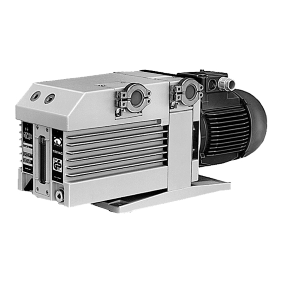
- Page 1 LEYBOLD VACUUM Vacuum Solutions Application Support Service GA 01.202/10.02 ® TRIVAC Rotary Vane Vacuum Pump D 16 B / D 25 B Cat.-No. 112 65/66/75/76 113 25/27/28/29 113 33/35/36/37/38/39/48 113 70/72/80/82 Operating Instructions...
-
Page 2: Table Of Contents
Contents Contents Page IMPORTANT SAFETY CONSIDERATIONS . .4 Description ......6 Function ......6 Supplied Equipment . - Page 3 Note We strongly recommend that you read Leybold-Service these Operating Instructions with care so as If a pump is returned to LEYBOLD, indicate whether the to ensure optimum operation of the pump pump is free of substances damaging to health or right from the start.
-
Page 4: Important Safety Considerations
This product must be operated and maintained by trained per- sonnel only. Consult local, state, and national agencies regarding specific requirements and regulations. Address any further safety, operation and/or maintenance questions to your nearest Leybold Vacuum office. Warning Failure to observe the following precautions could result in serious personal injury: •... - Page 5 Caution Failure to observe the following precautions could result in damage to the pump: • Do not allow the ingestion of small objects (screws, nuts, washers, pieces of wire, etc.) through the inlet port. Always use the screen which is supplied with every pump. •...
-
Page 6: Description
Description Key to Fig. 1 1 Oil filter OF 4-25 2 Exhaust filter AF 16-25 3 Condensate trap AK 16-25 Fig. 1 TRIVAC-B with accessories 1 Description 1.1 Function The rotor (2/7), mounted eccentrically in the pump hou- TRIVAC-B pumps are oil-sealed rotary vane pumps. The sing (2/6), has two radially sliding vanes (2/5) which divi- TRIVAC D16 B and D 25 B are dual-stage pumps. - Page 7 Description Key to Fig. 2 1 Intake port 2 Dirt trap 3 Anti-suckback valve 4 Intake channel 5 Vanes 6 Pump chamber 7 Rotor 8 Cover plate, connection for inert gas ballast 9 Exhaust channel 10 Exhaust valve 11 Internal demister 12 Spring buckles 13 Cover plate, connection for oil filter Fig.
-
Page 8: Supplied Equipment
Description Key to Fig. 3 1 Accessories 2 Bearings 3 Non-return valve 4 Pump chamber of the TRIVAC 5 Oil reservoir 6 Oil pump Fig. 3 Schematic of the lubricating system Key to Fig. 4 1 Oil reservoir 5 Valve seat 2 Spring 6 Valve disk 3 Control piston... -
Page 9: Accessories
Description 1.3 Accessories 1.4 Spare Parts Cat. No. / Ref. No. Set of gaskets 197 21 Pump module, complete D 16 B 200 10 956 Condensate trap AK16-25, DN 25 KF 188 11 D 25 B 200 10 960 Exhaust filter AF16-25, DN 25 KF 189 11 Module-gasket 200 10 736*) -
Page 10: Technical Data
Ultimate partial pressure without gas ballast Ultimate total pressure without gas ballast Ultimate total pressure with gas ballast Fig. 5 Pumping speed characteristics of the TRIVAC D 16 B and TRIVAC D 25 B, 50 Hz operation, SI units GA 01.202/10.02 - 08/01... - Page 11 Description 1.6.1 Motor related data D 16 B D 25 B Cat. No. W (kg) Cat. No. W (kg) Motor connection Motor Rated Speed Motor Order No. (mm) (mm) voltage, frequency power current noise level motor 112 65 1~, 230 V, 50 Hz 550 W 1400 48 dB(A)
-
Page 12: Operation
Operation Key to Fig. 7 1 Handle 2 Intake port 3 Exhaust port 4 Oil-level glass 5 Gas ballast knob 6 Threaded connection M 16 x 1.5 for inert gas ballast 7 Adapter 8 Cover plate 9 Cover plate; connection for oil filter Abb. -
Page 13: Electrical Connection
Operation The maximum throughput of the pump is equivalent to 2.3 Electrical Connections the pumping speed of the pump (see Section 1.6). Warning Before wiring the motor or altering the wiring, ensure that mains supply for the Caution The cross-section of the intake and exhaust pump is off and that it can not be applied lines should be at least the same size as inadvertently. -
Page 14: Start-Up
Operation Star connection Delta connection Fig. 8 Connection diagram for TRIVAC-B with 50 Hz 3-phase motor Caution After connecting the motor and after every Warning The safety regulations which apply to the time you alter the wiring, check the direction application in each case must be observed. -
Page 15: Operation
Operation 2.4.2 Remarks for Pumps with When pumping vapours ensure that the gas ballast valve is open and that the pump has been warmed up for EExe II T3-Motors approximately 30 minutes with the intake line closed. There are no objections against using the vacuum pump in an explosion hazard area of ZONE 1, a temperature Caution Vapour phases may only be pumped up to... -
Page 16: Switching Off/Shutdown
Operation 2.6 Switching Off/Shutdown 2.6.1 Shut-Down through Monitoring Com- ponents Under normal circumstances, all that you need do is to Warning electrically switch off the TRIVAC-B. When the pump has been switched off due to overheating sensed by the motor coil pro- No further measures will be required. -
Page 17: Maintenance
Maintenance 3 Maintenance 3.1 Checking the Oil Level During operation of the TRIVAC-B the oil level must always remain between marks (9/2) and (9/3) on the oil- Warning Disconnect the electrical connections befo- level glass. The amount of oil must be checked and top- re disassembling the pump. -
Page 18: Oil Change
Maintenance 3.2 Oil Change Warning Before pumping oxygen (or other highly reactive gases) at concentrations excee- ding the concentration in the atmosphere (> 21 % for oxygen) it will be necessary to use a special pump. Such a pump will have to be modified and de-greased, and an inert special lubricant (like PFPE) must be used. -
Page 19: Removing And Fitting The Internal Demister
Maintenance Key to Fig. 10 1 Oil case 2 Spring buckles 3 Demister 4 Frame for demister 5 Hex. socket screws (5 pcs.) 6 Silencing nozzle 7 Gasket Fig. 10 Removal and fitting of the internal demister 3.4 Removing and Fitting Remove the five recessed screws (10/5) on the oil case (10/1). -
Page 20: Disassembly And Reassembly Of The Electric Motor
Maintenance Key to Fig. 11 1 Gasket 2 Handle 3 Hex. socket screw 4 Electric motor 5 Intermediate flange 6 Hex. socket screw 7 Coupling 8 Threaded pin Fig. 11 Disassembly and reassembly of the electric motor 3.5 Disassembly and Reas- Remove the handle (11/2). -
Page 21: Replacing The Outer Shaft Seal
Maintenance Key to Fig. 12 1 Coupling element 2 Hexagon socket screw 3 Spring washer 4 Coupling (one half) 5 Key 6 Bushing 7 O-ring 8 Shaft seal 9 Centering disk 10 Hexagon socket screws Position of the shaft seal Fig. -
Page 22: Removing And Remounting The Pump Module
Maintenance Key to Fig. 13 1 Hex. nuts 2 Pump module 3 Washer 4 Gasket 5 Coupling element 6 Tie rods Fig. 13 Removing and Remounting the Pump Module 3.7 Removing and Remoun- If you do not have a shaft seal driver, place the shaft seal on the centering disk and carefully force it in with light ting the Pump Module blows of the plastic hammer. - Page 23 Maintenance Before installing a new pump module, remove the four tie rods from the new module and insert them in the old one for protection during shipment. 3.7.2 Remounting the Pump Module When installing a new pump module, it is also advisable to use a new gasket (13/4).
-
Page 24: Service At Leybold's
Maintenance 3.8 Service at Leybold’s 3.9 Storing the Pump If a pump is returned to Leybold, indicate whether the Caution Before putting a pump into operation once pump free of substances damaging to health or whether more it should be stored in a dry place pre- it is contaminated. -
Page 25: Maintenance Plan
Maintenance 3.10 Maintenance Plan (Recommendation) Rotary vane pumps Measurement/test quantity Interval Remarks TRIVAC D 16 B Operating/auxiliary VE VP 6m a n-a Refer also to the Operating Instructions TRIVAC D 25 B materials – Chapter: individual components. Operate the pump for at least 0.8 Condensed water is thus removed from the oil. -
Page 26: Troubleshooting
Troubleshooting 4 Troubleshooting Fault Possible cause Remedy Repair* Pump does not Wiring is malfunctioning. Check and repair wiring. start. Motor protection switch incorrectly set Set motor protection switch properly. (3-phase motors only). Operating voltage does not match motor. Replace the motor. Motor is malfunctioning. - Page 27 GA 01.202/10.02 - 08/01...
-
Page 28: Eec Declaration Of Conformity
EEC Declaration of Conformity We – LEYBOLD Vakuum GmbH – herewith declare that The products conform to the following directives: the products defined below meet the basic requirements • EC Directive on Machinery (98/37/EG) regarding safety and health of the relevant EC directives by design, type and versions which are brought into •... -
Page 29: Eec Manufacturer's Declaration
EEC Manufacturer’s Declaration in the sense of the Directive on Machinery 89/392/EWG, Annex IIb We – Leybold Vacuum GmbH – herewith declare that Applied harmonised standards: operation of the incomplete machine defined below, is • DIN EN 292 Part 1 11.91... - Page 30 Sales Net worldwide AMERICA EUROPE ASIA USA: Deutschland: Groß-Britannien/Irland: Volksrepublik China: Singapore: LEYBOLD VACUUM USA LEYBOLD VAKUUM LEYBOLD LTD. LEYBOLD (Tianjin) BALZERS and LEYBOLD 5700 Mellon Road GmbH Waterside Way, VACUUM EQUIPMENT Singapore Pte. Ltd. Export, PA 15632 Bonner Straße 498 Plough Lane MANUFACTURING Co.,...
Need help?
Do you have a question about the TRIVAC D 16 B and is the answer not in the manual?
Questions and answers