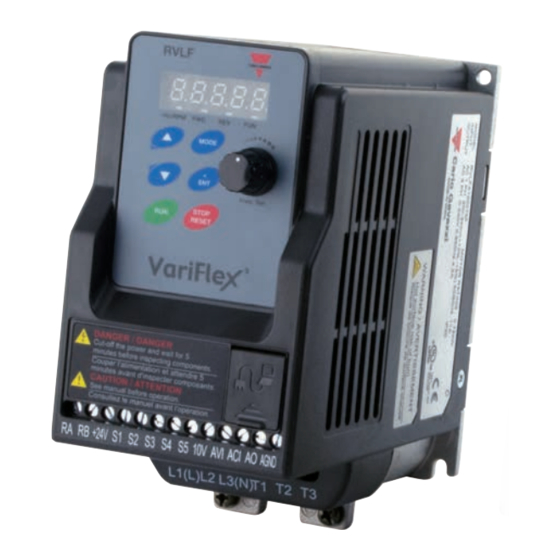
CARLO GAVAZZI VariFlex3 RVLF Series Manual
Motor controllers ac variable frequency drives
Hide thumbs
Also See for VariFlex3 RVLF Series:
- Manual (430 pages) ,
- Quick start manual (99 pages) ,
- Manual (66 pages)

Related Manuals for CARLO GAVAZZI VariFlex3 RVLF Series


Summary of Contents for CARLO GAVAZZI VariFlex3 RVLF Series
- Page 1 CARLO GAVAZZI A u t o m a t i o n C o m p o n e n t s Motor Controllers AC Variable Frequency Drives Type VariFlex RVLF...
- Page 2 Motor Controllers AC Variable Frequency Drives Type VariFlex RVLF RVLF Series 100V 0.4-0.75kW (0.5-1HP) 200V 0.4-2.2kW (0.5-3HP) 400V 0.75-2.2kW (1-3HP) Specifications are subject to change without notice. Pictures are just an example. For special features and/or customization, please ask to our sales network. 13/12/2017...
-
Page 3: Table Of Contents
Motor Controllers AC Variable Frequency Drives Type VariFlex RVLF Index 0. Preface 1. Safety Precautions 1.1. Before power UP 1.2. During power UP 1.3. Before operation 1.4. During operation 1.5. Inverter disposal 2. Part Number Definition 2.1. Model part number 2.2. - Page 4 Motor Controllers AC Variable Frequency Drives Type VariFlex RVLF 4. Software Index 4.1. Keypad description 4.1.1 Operator panel functions 4.1.2 Digital display description 4.1.3 Digital display setup 4.1.4 Example of keypad operation 4.1.5 Operation control 4.2. Programmable parameter groups 4.3. Parameter function description 5.
-
Page 5: Preface
Motor Controllers AC Variable Frequency Drives Type VariFlex RVLF 0 Preface To extend the performance of the product and ensure personnel safety, please read this manual thoroughly before using the inverter. Should there be any problem in using the product that cannot be solved with the information provided in the manual, contact our technical or sales representative who will be willing to help you. -
Page 6: Safety Precautions
Motor Controllers AC Variable Frequency Drives Type VariFlex RVLF 1. Safety Precautions 1.1. Before Power Up Danger Make sure the main circuit connections are correct. Single phase L1 (L), L3 (N), and Three phase L1(L), L2, L3 (N); 400V: L1, L2, L3 are power-input terminals and must not be mistaken for T1, T2 and T3. -
Page 7: During Power Up
Motor Controllers AC Variable Frequency Drives Type VariFlex RVLF 1.2. During Power Up Danger When the momentary power loss is longer than 2 seconds, the inverter will not have sufficient stored power for its control circuit. Therefore, when the power is re-applied, the run operation of the inverter will be based on the setup of following parameters: •... -
Page 8: During Operation
Motor Controllers AC Variable Frequency Drives Type VariFlex RVLF 1.4. During Operation Danger Do not connect or disconnect the motor during operation. Otherwise, It may cause the inverter to trip or damage the unit. Danger • To avoid electric shock, do not take the front cover off while power is on. •... -
Page 9: Part Number Definition
Motor Controllers AC Variable Frequency Drives Type VariFlex RVLF 2. Part Number Definition 2.1. Model Part Number Ordering Key RVLF A 1 20 075 F A VariFlex AC Drive Frame Size A/B AC Supply Phase 1/3 Drive Voltage Rating Drive kW Rating Filter Advance Frame Size... -
Page 10: Environment & Installation
Motor Controllers AC Variable Frequency Drives Type VariFlex RVLF 3. Environment & Installation 3.1. Environment Installation environment has a direct affect on the correct operation and the life expectancy of the inverter, Install the inverter in an environment complying with the following conditions: Protection Protection class IP20, NEMA/UL Open Type... -
Page 11: Installation
Motor Controllers AC Variable Frequency Drives Type VariFlex RVLF 3.2. Installation 3.2.1. Installation methods Frame1. Mounting on a flat surface. RVLF Ha/RPM MODE < Freq. Set STOP RESET DIN rail type installation: DIN rail kit includes a plastic and a metal adaptor plates. Assembly Steps: 1) Attach the metal adaptor plate to the inverter base with the screws provided. - Page 12 Motor Controllers AC Variable Frequency Drives Type VariFlex RVLF Frame 2. Mounting on a flat surface. DIN rail type installation: DIN rail kit includes a plastic adaptor plate as an attachment for the inverter base. Refer to diagram below: DIN rail mounting & dismounting as shown in the diagram below: Use a 35mm DIN rail. CLICK Plastic adaptor plate.
- Page 13 Motor Controllers AC Variable Frequency Drives Type VariFlex RVLF Frame 3. Mounting on a flat surface. Frame 3. Mounting on a flat surface. Specifications are subject to change without notice. Pictures are just an example. For special features and/or customization, please ask to our sales network. 13/12/2017...
-
Page 14: Installation Space
Motor Controllers AC Variable Frequency Drives Type VariFlex RVLF 3.2.2. Installation Space Provide sufficient air circulation space for cooling as shown in examples below. Install the Inverter on surfaces that provide good heat dissipation. Single unit Installation Install the inverter verticality to obtain effective cooling Frames 1 &... -
Page 15: Derating Curve
Motor Controllers AC Variable Frequency Drives Type VariFlex RVLF 3.2.3. Derating Curve Curves below show the applicable output current de-rate due to setting of carrier frequency and the ambient operating temperatures of 40 and 50°C. RVLFA*2**FA (40°C) RVLFA1100**A (40°C), RVLFB*2****A (50°C) Rated Current (In) Rated Current (In) 100%... -
Page 16: Capacitor Reforming Guide After Long Storage
Motor Controllers AC Variable Frequency Drives Type VariFlex RVLF 3.2.4 Capacitor reforming guide after long storage For correct performance of this product after long storage before use it is important that Inverter Capacitors are reformed according to the guide below: Storage time Procedure to re-apply voltage ≤... - Page 17 Motor Controllers AC Variable Frequency Drives Type VariFlex RVLF Example power connections: inverter with dedicated power line. MCCB Power MCCB Power Inverter Inverter MCCB Power Inverter MCCB Filter Power MCCB Power Install a supply RFI filter or Isolation transformer when the power source is shared with other Inverter Machine Inverter...
-
Page 18: Control Cable Selection And Wiring
Motor Controllers AC Variable Frequency Drives Type VariFlex RVLF 3.3.2. Control Cable selection and Wiring Control cables should be connected to terminal block TM2. Choose power & control cables according to the following criteria: • Use copper wires with correct diameter and temperature rating of 60/75°C. •... -
Page 19: Wiring And Emc Guidelines
Motor Controllers AC Variable Frequency Drives Type VariFlex RVLF 3.3.3. Wiring and EMC Guidelines. For effective interference suppression, do not route power and control cables in the same conduit or trucking. To prevent radiated noise, motor cable should be put in a metal conduit. Alternatively an armored or shielded type motor cable should be used. -
Page 20: Failure Liability
Motor Controllers AC Variable Frequency Drives Type VariFlex RVLF 3.3.4. Failure Liability • Carlo Gavazzi bears no responsibility for any failures or damages caused to the inverter if the recommendations in this instruction manual have not been followed specifically points listed below. -
Page 21: Considerations For Peripheral Equipment
Motor Controllers AC Variable Frequency Drives Type VariFlex RVLF 3.3.5. Considerations for Peripheral Equipment Ensure that the supply voltage is correct. A molded- Power case circuit breaker or fused disconnect must be installed between the AC source and the inverter. Use a molded-case circuit breaker that conforms to the rated voltage and current of the inverter. -
Page 22: Ground Connection
Motor Controllers AC Variable Frequency Drives Type VariFlex RVLF 3.3.6. Ground Connection Inverter ground terminal must be connected to installation ground correctly and according to the required local wiring regulations. • Ground cable size must be according to the required local wiring regulations. Ground connection should be as short as possible. -
Page 23: Specifications
Motor Controllers AC Variable Frequency Drives Type VariFlex RVLF 3.4. Specifications 3.4.1. Inverter exterior 100V Class: Single phase. Model: RVLF 110040 110075 Horse power (HP) Suitable motor capacity (KW) 0.75 Rated output current (A) Rated capacity (KVA) 1.00 1.65 Input voltage range(V) Single Phase: 110~120V, 50/60HZ Allowable voltage fluctuation +10%-15%... - Page 24 Motor Controllers AC Variable Frequency Drives Type VariFlex RVLF 400V Class: Three phase. F: Built-in Filter Model: RVLF 340075 340150 340220 Horse power (HP) Suitable motor capacity (KW) 0.75 Rated output current (A) Rated capacity (KVA) Input voltage range(V) Three phase: 380~480V, 50/60HZ Allowable voltage fluctuation +10% Output voltage range(V)
-
Page 25: General Specifications
Motor Controllers AC Variable Frequency Drives Type VariFlex RVLF 3.4.2. General Specifications Item RVLF Control Mode V/F Control + SLV Range 0.01~599.00Hz Speed Accuracy V/F: 3% (100% torque) SLV: 1% Keypad: Set directly with keys or the VR (Potentiometer) on the keypad Frequency External input terminals: Setting... - Page 26 Motor Controllers AC Variable Frequency Drives Type VariFlex RVLF Display: parameter/parameter value/frequency/line speed/ DC voltage/output voltage/ output current/PID feedback/ Display input and output terminal sta- tus/heat sink temperature/Pro- gram version/Fault Log. For run/stop/forward and re- LED Status indicator verse. Integrated motor and Inverter overload protection.
-
Page 27: Standard Wiring
Motor Controllers AC Variable Frequency Drives Type VariFlex RVLF 3.5. Standard wiring 3.5.1. Single phase (NPN input) Magnetic Thermal Contactor relay MCCB L1( L) Power Inverter Induction source output Motor input Thermal L3( N) relay ON-OFF Ground Surge Suppressor Pin 1 to Pin 8 CON2 FWD (Run/Stop) RS485... -
Page 28: Single Phase (Pnp Input)
Motor Controllers AC Variable Frequency Drives Type VariFlex RVLF 3.5.2. Single phase (PNP Input) Main Fuse switch L1(L) Power Inverter AC Power input output source L3(N) Ground 1:Data+ 2:Data- CON2 3:Data+ RS485 4:Reserved Multi-function input 5:Reserved Pin1 to Pin 8 6:Data- 7:5V 8:GND... -
Page 29: Three Phase (Npn Input)
Motor Controllers AC Variable Frequency Drives Type VariFlex RVLF 3.5.3.Three phase (NPN Input) Magnetic Thermal Contactor relay MCCB L1( L) Power Inverter Induction source output Motor input Thermal L3( N) relay ON-OFF Ground Surge Suppressor Pin 1 to Pin 8 CON2 FWD (Run/Stop) RS485... -
Page 30: Three Phase (Pnp Input)
Motor Controllers AC Variable Frequency Drives Type VariFlex RVLF 3.5.4. Three phase (PNP Input) Magnetic Thermal Contactor relay MCCB L1( L) Power Inverter Induction source output Motor input Thermal L3( N) relay ON-OFF Ground Surge Suppressor Pin 1 to Pin 8 CON2 FWD (Run/Stop) RS485... -
Page 31: Three Phase (Pnp - Npn)
Motor Controllers AC Variable Frequency Drives Type VariFlex RVLF 3.5.5. Three phase (PNP / NPN) Thermal Magnetic relay MCCB Contactor Inverter Induction Power output Motor input source Thermal relay ON-OFF Ground Surge Suppressor Pin 1 to Pin 8 CON2 FWD (Run/Stop) RS485 REV (Run/Stop) Multifunction... -
Page 32: Terminal Description
Motor Controllers AC Variable Frequency Drives Type VariFlex RVLF 3.6. Terminal Description 3.6.1. Terminal Description Terminal symbols TM1 Function Description Main power input, Single Phase L1(L)/ L3(N) L1(L) Three Phase (200V): L1(L)/ L2/ L3 (N) L3(N) Three Phase (400V): L1/ L2/ L3 Externally connected braking resistor Inverter output, connect to U, V, W terminals of motor Ground terminal... -
Page 33: Control Circuit Terminal Description
Motor Controllers AC Variable Frequency Drives Type VariFlex RVLF 3.6.2. Control Circuit Terminal Description Frame A & B Terminal TM1 Function Description Signal Level Relay output terminal, Specification: 250VAC/1A 250VAC/ 1A (30VDC/ 1A) (30VDC/1A) S1~S5 (COMMON) NPN +/-15%, Max output 30mA +24V S1~S5 (COMMON) PNP +/-15%, Max output 30mA... - Page 34 Motor Controllers AC Variable Frequency Drives Type VariFlex RVLF Frame C & D Terminal TM1 Function Description Signal Level Relay output terminal, Specification: 250VAC/1A (30VDC/1A) RA-NO; RB-NC; RC-Common 250VAC/ 1A (30VDC/ 1A) +24V S1~S5 (COMMON) PNP +/-15%, Max output 30mA PNP input: COM&SC needs shorted 24VDC, 4.5mA, optical coupling isolation (Max voltage Multi-function input terminals (refer to group 3)
-
Page 35: Outline Dimension
Motor Controllers AC Variable Frequency Drives Type VariFlex RVLF 3.7. Outline Dimensions Size A 2-Ø4.3 2-R2.2 55±0.5 81.1±0.5 86.3±0.5 Model RVLFA120040FA RVLFA120075FA RVLFA320040A 144.2 128.2 86.3 81.1 RVLFA320075A RVLFA110040A RVLFA110075A F: Built-in EMC filter Specifications are subject to change without notice. Pictures are just an example. For special features and/or customization, please ask to our sales network. 13/12/2017... - Page 36 Motor Controllers AC Variable Frequency Drives Type VariFlex RVLF Size B 2-Ø4.3 2-R2.2 51.5 ±0.5 96.7 ±0.5 101.3 ±0.5 Model RVLFB120150FA RVLFB120220FA RVLFB320040A RVLFB320075A 152.2 144.2 136.4 101.3 96.7 51.5 RVLFB340075FA RVLFB340150FA RVLFB340220FA F: Built-in EMC filter Specifications are subject to change without notice. Pictures are just an example. For special features and/or customization, please ask to our sales network. 13/12/2017...
- Page 37 Motor Controllers AC Variable Frequency Drives Type VariFlex RVLF Size C and D Model RVLFC340370FA 197.5 177.6 143.7 102.6 48.2 RVLFC340550FA RVLFD340750FA 249.8 228.6 185.6 177.9 84.7 RVLFB3401100FA F: Built-in EMC filter Specifications are subject to change without notice. Pictures are just an example. For special features and/or customization, please ask to our sales network. 13/12/2017...
-
Page 38: Filter Disconnection
Motor Controllers AC Variable Frequency Drives Type VariFlex RVLF 3.8. Filter Disconnection EMC filter may be disconnected: Inverter drives with built-in EMC filter are not suitable for connection to certain type of supply systems, such as listed below; in these cases the RFI filter can be disabled. In all such cases consult your local electrical standards requirements. -
Page 39: Software Index
Motor Controllers AC Variable Frequency Drives Type VariFlex RVLF 4. Software Index 4.1. Keypad Description 4.1.1. Operator Panel Functions Type Item Function Main digital Frequency display, parameter, voltage, current, temperature, displays fault messages. Hz/RPM: ON when the frequency or line speed is displayed. Digital OFF when the parameters are displayed. - Page 40 Motor Controllers AC Variable Frequency Drives Type VariFlex RVLF 3.8. Filter Disconnection EMC filter may be disconnected: Inverter drives with built-in EMC filter are not suitable for connection to certain type of supply systems, such as listed below; in these cases the RFI filter can be disabled. In all such cases consult your local electrical standards requirements.
- Page 41 Motor Controllers AC Variable Frequency Drives Type VariFlex RVLF 4. Software Index 4.1. Keypad Description 4.1.1. Operator Panel Functions Type Item Function Main digital Frequency display, parameter, voltage, current, temperature, displays fault messages. Hz/RPM: ON when the frequency or line speed is displayed. Digital OFF when the parameters are displayed.
-
Page 42: Digital Display Description
Motor Controllers AC Variable Frequency Drives Type VariFlex RVLF 4.1.2. Digital Display Description Alpha numerical display format Digit Letter Letter Symbol ° • Digital display indication formats Actual output frequency Set frequency Digits are lit continually Preset digits flashing Selected digit flashing Specifications are subject to change without notice. - Page 43 Motor Controllers AC Variable Frequency Drives Type VariFlex RVLF LED display example Display Description In stop mode shows the set frequency In run mode shows the actual output frequency Hz/RPM Selected parameter Hz/RPM Hz/RPM Hz/RPM Parameter value Hz/RPM Hz/RPM Hz/RPM Output voltage Hz/RPM Hz/RPM...
- Page 44 Motor Controllers AC Variable Frequency Drives Type VariFlex RVLF 4.1.3 Digital Display Set Up MODE On power up digital display screens will be as shown below. User selectable display formats: MODE 2sec later 12-00 Display Mode 0 0 0 parameter frequency Power supply High...
- Page 45 Motor Controllers AC Variable Frequency Drives Type VariFlex RVLF MODE Temperature DC voltage MODE MODE Example 2. Set parameter 2: 12-00=[12345] to obtain the display format shown below. < 4 > < 3 > MODE PIDfeedback Temperature MODE DC voltage MODE Output Voltage MODE...
-
Page 46: Example Of Keypad Operation
Motor Controllers AC Variable Frequency Drives Type VariFlex RVLF 4.1.4. Example of Keypad Operation Example1: Modifying parameters Frequency Short press MODE once Short press Short press </ENT twice </ENT once Short press once Long press Short press </ENT once once Long press </ENT once Specifications are subject to change without notice. - Page 47 Motor Controllers AC Variable Frequency Drives Type VariFlex RVLF Example 2: Modifying the frequency from keypad in run and stop modes. Modify frequency in stopping Modify frequency in operating Power Supply Power supply 2sec later 2sec later Set frequency display Set frequency display Press RUN Short time press...
-
Page 48: Operation Control
Motor Controllers AC Variable Frequency Drives Type VariFlex RVLF 4.1.5. Operation Control Stop Stop Actual Outpt frequency Power Specifications are subject to change without notice. Pictures are just an example. For special features and/or customization, please ask to our sales network. 13/12/2017... -
Page 49: Programmable Parameter Groups
Motor Controllers AC Variable Frequency Drives Type VariFlex RVLF 4.2. Programmable Parameter Groups Parameter Group No. Description Group 00 Basic parameters Group 01 V/F Pattern selections & setup Group 02 Motor parameters Group 03 Multi function digital Inputs / Outputs Group 04 Analog signal Inputs / Analog output Group 05... - Page 50 Motor Controllers AC Variable Frequency Drives Type VariFlex RVLF Group 00 The basic parameters group Factory Description Range Unit Note setting 0: V/F model 00-00 Motor rotation 1: SLV model 0: Forward 00-01 Motor rotation 1: Reverse 0: Keypad Main run 00-02 1: External Run/Stop control source selection...
- Page 51 Motor Controllers AC Variable Frequency Drives Type VariFlex RVLF Group 01 V/F Pattern selection & setup Factory Description Range Unit Note setting 01-00 Volts/Hz patterns 200V: 198.0~256.0 Based on 01-01 V/F max voltage 400V: 323.0~528.0 13-08 01-02 Max frequency 0.20~599.00 50.00/60.00 01-03 Max frequency voltage ratio 0.0~100.0...
- Page 52 Motor Controllers AC Variable Frequency Drives Type VariFlex RVLF Group 03 Multifunction digital inputs / outputs Factory Description Range Unit Note setting 03-00 Multifunction input term. S1 0: Forward/Stop command or Run/Stop 03-01 Multifunction input term. S2 1: Reverse/Stop command or REV/WD 03-02 Multifunction input term.
- Page 53 Motor Controllers AC Variable Frequency Drives Type VariFlex RVLF Group 03 Multifunction digital inputs / outputs Factory Description Range Unit Note setting 03-12 Reserved 03-13 Output frequency detection level (Hz) 0.00~599.00 0.00 03-14 Frequency detection band 0.00~30.00 2.00 03-15 Output current detection level 0.1~999.9 03-16 Output current detection period 0.1~10.0...
- Page 54 Motor Controllers AC Variable Frequency Drives Type VariFlex RVLF Group 05 Preset frequency selections Factory Description Range Unit Note setting 0: Common Accel/Decel Accel/Decel 1 or 2 apply to all speeds Preset speed control mode 05-00 selection 1: Individual Accel/Decel Accel/ Decel 0-7 apply to the selected preset speeds (Acc0/ Dec0~Acc7/Dec7) Preset speed 0...
- Page 55 Motor Controllers AC Variable Frequency Drives Type VariFlex RVLF Group 06 Auto run (Auto Sequencer) function Factory Description Range Unit Note setting 0: Disabled. 1: Single cycle. (Continues to run from the unfinished step if restarted). 2: Periodic cycle. (Continues to run from the unfinished step if restarted).
- Page 56 Motor Controllers AC Variable Frequency Drives Type VariFlex RVLF Group 06 Auto run (Auto Sequencer) function Factory Description Range Unit Note setting 06-34 Auto Run mode running direction 2 06-35 Auto Run mode running direction 3 0: Stop 06-36 Auto Run mode running direction 4 1: Forward 06-37 Auto Run mode running direction 5 2: Reverse...
- Page 57 Motor Controllers AC Variable Frequency Drives Type VariFlex RVLF Group 08 Drive & motor protection functions Factory Description Range Unit Note setting xxxx0: Enable trip prevention during acceleration xxxx1: Disable trip prevention during acceleration xxx0x: Enable trip prevention during deceleration xxx1x: Disable trip prevention during deceleration 08-00 Trip prevention selection 00000...
- Page 58 Motor Controllers AC Variable Frequency Drives Type VariFlex RVLF Group 08 Drive & motor protection functions Factory Description Range Unit Note setting 08-12 PTC Detection Time Delay 1 ~ 300 08-13 PTC Protection Level 0.1 ~ 10.0 08-14 PTC Detection Level 0.1 ~ 10.0 08-15 PTC Warning Level 0.1 ~ 10.0...
- Page 59 Motor Controllers AC Variable Frequency Drives Type VariFlex RVLF Group 10 PID function setup Factory Description Range Unit Note setting 0: Potentiometer on keypad 1: Analog signal input. (AVI) PID target value selection (when 2: Analog signal input. (ACI) 10-00 00-05\00-06=6 ,this function is 3: Frequency set by communication enabled)
- Page 60 Motor Controllers AC Variable Frequency Drives Type VariFlex RVLF Group 11 Performance control functions Factory Description Range Unit Note setting 0: Reverse command is enabled 11-00 Reverse operation control 1: Reverse command is disabled 11-01 Carrier frequency (kHz) 1~16 0: Mode 0, 3 phase PWM modulation 11-02 Carrier mode selection 1: Mode 1, 2 phase PWM modulation 2: Mode 2, 2 phase random PWM modulation...
- Page 61 Motor Controllers AC Variable Frequency Drives Type VariFlex RVLF Group 12 Digital display & monitor functions Modbus Register Factory Description Range Unit example Note setting value S2 S3 S4 S5 Inputs and output logic 12-05 0C05H status display (S1 to ----- S5) &...
-
Page 62: Parameter Function Description
Motor Controllers AC Variable Frequency Drives Type VariFlex RVLF 4.3. Parameter Function Description 00-00 Control Mode [0]: V/F mode Range [1]: SLV mode Select the relevant control mode for the application, using parameter 00-00 Control mode. Default control mode is V/F. V/F mode can be used for most applications specifically multi-motor or applications where auto tune is not successful or when a customized V/F pattern may be required. - Page 63 Motor Controllers AC Variable Frequency Drives Type VariFlex RVLF 00-04 Operation modes for external terminals [0]: Forward/stop-reverse/stop Range [1]: Run/Stop-forward/reverse [2]: 3-wire control mode-run/stop 00-02(Main Run Source) = 1 or 00-03(Alternative Run source) = 1 (When 00-02/00-03=1, the command comes from External Run /Stop) Parameters 03-00 to 03-04, which are used to set the required function for the digital inputs [S1 to S5](multi-function inputs).
- Page 64 Motor Controllers AC Variable Frequency Drives Type VariFlex RVLF Two external switches are required. Switch type: two position, maintained type. (This is two wire mode). S1 (FWD/STOP) 1. Run/Stop switch S2 (REW/STOP) Select one of the multifunction inputs [S1 to S5] and set the relevant parameter 03-00 to 03-04 = 0 (Run/Stop mode.) 2.
- Page 65 Motor Controllers AC Variable Frequency Drives Type VariFlex RVLF 00-08 Communication Frequency Command Range [0.00~650.00] Hz This parameter can be used to read the set frequency in communication mode. This parameter is only effective in the communication mode. 00-09 Frequency Command save on power down (Communication mode) [0]: disable Range [1]: enable...
- Page 66 Motor Controllers AC Variable Frequency Drives Type VariFlex RVLF Frequency upper limit Frequency Lower limit 00-14 Acceleration time 1 Range [0.1~3600.0] s 00-15 Deceleration time 1 Range [0.1~3600.0] s 00-16 Acceleration time 2 Range [0.1~3600.0] s 00-17 Deceleration time 2 Range [0.1~3600.0] s Preset acceleration and deceleration times by above parameters are the time taken for the...
- Page 67 Motor Controllers AC Variable Frequency Drives Type VariFlex RVLF Maximum output Frequency Set frequency Minimum starting frequency Actual acc-time Actual dec-time Acc-time 00-14 Dec-time 00-15 Maximum output frequency is for V/F curve, which can be checked from table when V/F curve is fixed.
- Page 68 Motor Controllers AC Variable Frequency Drives Type VariFlex RVLF 01-V/F command group 01- 00 Volts/Hz Patterns (V/F) Range [1-7] Set 01-00 to one of the following preset V/F selections [1~6] according to the required application. Parameters 01-02~01-09 are not applicable. Six fixed V/F patterns are shown below.
- Page 69 Motor Controllers AC Variable Frequency Drives Type VariFlex RVLF 01- 01 V/F Maximum voltage 200: [198.0~256.0] V Range 400: [323.0~528.0] V 01-02 Maximum Frequency Range [0.20~599.00] Hz 01-03 Maximum Frequency Voltage Ratio Range [0.0~100.0] % 01-04 Medium Frequency 2 Range [0.10~599.00] Hz 01-05 Medium Frequency Voltage Ratio 2...
- Page 70 Motor Controllers AC Variable Frequency Drives Type VariFlex RVLF (V)% 01-10 2.5/3.0 50/60 01-11 V/F start Frequency Range [0.00~10.00] Hz V/F Start frequency is for occasion where start frequency higher than zero Hz is needed. 01-12 No-load oscillation suppression gain Range [0.00~200.0] % If the control mode is set to V/F control and the motor is operating under light load conditions...
- Page 71 Motor Controllers AC Variable Frequency Drives Type VariFlex RVLF 01- 16 Auto-Torque Compensation Filter Coefficient Range [0.1 ~ 1000.0]ms 01- 17 Auto-torque Compensation Gain Range [0~ 100]% 01- 18 Auto-torque Compensation Frequency Range [1.30 ~ 5.00]Hz • In V/F control mode, auto torque compensation can only be achieved with parameters 01-16 to 01- 18.
- Page 72 Motor Controllers AC Variable Frequency Drives Type VariFlex RVLF 02-Motor parameter group 02-00 Motor no load current Output Current-(02-00) Range ---- Slip compensation boost= x(02-02)xRate motor slip (02-01)-(02-00) 02-01 Motor rated current Range ---- 02-02 Motor rated slip compensation Output Current-(02-00) Range [0.0~100.0] (%) Slip compensation boost=...
- Page 73 Motor Controllers AC Variable Frequency Drives Type VariFlex RVLF 02-08 Stator Resistor Gain Range ----- 02-09 Stator Resistor Gain Range ----- Auto tune function in SLV mode. 00-00=[1] • Set motor parameters 02-01 and 02-03~02-06, then set 02-07 to [1] to start the auto tune function.
- Page 74 Motor Controllers AC Variable Frequency Drives Type VariFlex RVLF 02-15 Low Frequency Torque Gain Range [0~100]% Inverter of dead zone (IGBT on short) will lower the torque of output in the system, leading to lower motor efficiency. Setting 02-15 can not only reduce this situation but also increase torque of output in low frequency.
- Page 75 Motor Controllers AC Variable Frequency Drives Type VariFlex RVLF 03-External digital inputs & realy output functions 03-00 Multifunction Input Term. S1 03-01 Multifunction Input Term. S2 03-02 Multifunction Input Term. S3 03-03 Multifunction Input Term. S4 03-04 Multifunction Input Term. S5 [0]: Forward/Stop command------------------------------- (Parameters 00-02/00-03=1 &...
- Page 76 Motor Controllers AC Variable Frequency Drives Type VariFlex RVLF Note: If both forward and reverse commands are ON, it will be treated as a STOP 2-Wire method. Mode 2. Example: RUN/STOP and REV/FWD from two inputs (S1&S2) Set 00-04= [1]; S1: 03-00= [0] (RUN/STOP); S2: 03-01= [1] (REV/FWD); (RUN /STOP)...
- Page 77 Motor Controllers AC Variable Frequency Drives Type VariFlex RVLF 2) Parameters 03-00~03-04= [4, 3, 2] Preset speed selections. Combination of any three terminals from S1~S5 can be used to select preset speed 0 to 7 according to the table below. Preset speed 0-7 and the related acceleration/decelerating times should be set in parameter group 5.
- Page 78 Motor Controllers AC Variable Frequency Drives Type VariFlex RVLF RUN Command STOP 7) 03-00~03-04= [12] Main/Alternative run source select. When an input terminal is set to function [12] and is turned on, the run command source is according to parameter 00-03 (alternative run source). If the Input is off it will be according to 00-02 (main run source). 8) 03-00~03-04= [13] Main/Alternative frequency source select When an input terminal is set to function [13] and is turned on, the frequency source is according to parameter 00-06 (alternative frequency source).
- Page 79 Motor Controllers AC Variable Frequency Drives Type VariFlex RVLF Actual output frequency △Hz △Hz Actual output frequency △Hz △Hz Mode 2: If UP or DOWN input terminals are turned on for more than 2 seconds, the original UP/ DOWN mode is restored output frequency ramps up or down as long as the input is kept ON. As shown in the diagram below.
- Page 80 Motor Controllers AC Variable Frequency Drives Type VariFlex RVLF 03-08 Multifunction terminals S1~S5 scan time Range [1~400] ms Multifunction input terminal On/Off periods will be scanned for the number of cycles according to the set value in parameter 03-08. If the signal status for on or off period is less than the set period it will be treated as noise.
- Page 81 Motor Controllers AC Variable Frequency Drives Type VariFlex RVLF Output relay RY1. Function descriptions: 1) 03-11 =[0]. RY1 will be ON with run signal. 2) 03-11 =[1]. RY1 will be ON with inverter faults. 3) 03-11 =[2]. RY1 will be ON when output frequency reached setting frequency. When Output Freq.
- Page 82 Motor Controllers AC Variable Frequency Drives Type VariFlex RVLF 5) 03-11= [4] RY1 will be on while output freq. > frequency detection level (03-13) When Output Freq.> (03-13), Relay output will be ON. Setting Freq. (03-13) Output Freq. Time Output Freq. (03-13) Setting Freq.
- Page 83 Motor Controllers AC Variable Frequency Drives Type VariFlex RVLF 100% I load 03-15 03-*16 Fixed Value 100msec 03-11 100% 03-17 Brake Release Level Range [0.00~20.00] Hz I load 03-18 Brake Engage Level 03-15 Range [0.00~20.00] Hz If 03-11 = [14] In accelerating mode.
- Page 84 Motor Controllers AC Variable Frequency Drives Type VariFlex RVLF Timing diagram for 03-17 > 03-18 is shown below: 03-17 03-18 STOP RUN command 03-11=14 03-19 Relay Output Status type [0]: A (Normally open) Range [1]: A (Normally close) V(v) 03-20 Brake Transistor ON Level AVI (0~10V): F (Hz)= x (00-12)
- Page 85 Motor Controllers AC Variable Frequency Drives Type VariFlex RVLF STOP RUN command STOP RUN command 03-11=14 04- External analog signal input / output functions 03-11=14 04-00 Analog Voltage & Current input selections [0]: 0~10V 0~20mA Range [1]: 0~10V 4~20mA [2]: 2~10V 0~20mA [3]: 2~10V 4~20mA...
- Page 86 Motor Controllers AC Variable Frequency Drives Type VariFlex RVLF 04-01 AVI Signal verification Scan Time Range [1~400] ms 04-02 AVI Gain Range [0~1000]% 04-03 AVI Bias Range [0~100]% 04-04 AVI Bias Selection Range [0]: Positive [1]: Negative 04-05 AVI Slope Range [0]: Positive [1]: Negative...
- Page 87 Motor Controllers AC Variable Frequency Drives Type VariFlex RVLF (2) Negative Bias type and effects of modifying Bias amount by parameter 04-03 and slope type with parameter 04-05 are shown in Fig 3 & 4. Figure 3: Figure 4: 04-02 04-03 04-04 04-05...
- Page 88 Motor Controllers AC Variable Frequency Drives Type VariFlex RVLF 04-03 04-03 04-03 bias 04-03 bias Upper bias Upper bias 04-03 100% 60Hz Upper 100% 60Hz Frequency Upper 100% 60Hz Frequency 04-03 bias 100% 60Hz Frequency Frequency 37.5Hz Upper 37.5Hz bias 37.5Hz 04-03 04-03...
- Page 89 Motor Controllers AC Variable Frequency Drives Type VariFlex RVLF 04-12 AO Gain Range [0~1000]% 04-13 AO Bias Range [0~100]% 04-14 AO Bias Selection Range [0]: Positive [1]: Negative 04-15 AO Slope Range [0]: Positive [1]: Negative • Select the analog output type for the multifunction analog output on terminal (TM2) as required by parameter 04-11.
- Page 90 Motor Controllers AC Variable Frequency Drives Type VariFlex RVLF 05- Preset Frequency Selections. 05-00 Preset Speed Control mode Selection [0]: Common Accel/Decel. Range [1]: Individual Accel/Decel for each preset speed 0-7. 05-01 Preset Speed 0 (Keypad Freq) 05-02 Preset Speed 1 05-03 Preset Speed 2 05-04...
- Page 91 Motor Controllers AC Variable Frequency Drives Type VariFlex RVLF • When 05-00= [0] Accel /Decel 1 or 2 set by parameters 00-14/00-15 or 00-16/00-17 apply to all speeds • When 05-00= [1] Individual Accel/Decel apply to each preset speed 0-7. Parameters 05-17 to 05-32.
- Page 92 Motor Controllers AC Variable Frequency Drives Type VariFlex RVLF 05-03 05-03 05-03 05-03 05-02 05-02 05-02 05-02 05-03 Preset Preset Preset Preset speed2 speed2 speed2 speed2 05-01 05-01 05-01 05-01 05-02 Preset Preset Preset Preset speed1 speed1 speed1 speed1 Preset Preset Preset Preset...
- Page 93 Motor Controllers AC Variable Frequency Drives Type VariFlex RVLF When the run command is continuous, acceleration and deceleration times for each segment can be calculated as below: (05-17)x(05-01) (05-19)x[(05-02)-(05-01)] Ex: 01-02 01-02 (05-24)x[(05-03)-(05-04)] (05-21)x[(05-03)-(05-02)] 01-02 01-02 (05-26)x(05-05) (05-27)x(05-05) (05-28)x(05-05) 01-02 01-02 01-02 (05-29)x(05-05)
- Page 94 Motor Controllers AC Variable Frequency Drives Type VariFlex RVLF 06-16 Auto Run Mode Running Time Setting 0 06-17 Auto Run Mode Running Time Setting 1 06-18 Auto Run Mode Running Time Setting 2 06-19 Auto Run Mode Running Time Setting 3 06-20 Auto Run Mode Running Time Setting 4 06-21...
- Page 95 Motor Controllers AC Variable Frequency Drives Type VariFlex RVLF Example 2. Periodic cycle Run. Mode: 06-00=[2] or [5] The inverter will repeat the same cycle periodically. All other parameters are set same as example 1. shown above. 06-02 06-02 06-01 06-01 05-01 05-01...
- Page 96 Motor Controllers AC Variable Frequency Drives Type VariFlex RVLF Command stop Output Frequency Continue running from unfinished step Example 4 & 5. time Auto Run Mode 06-00= [1~3]. After a restart continues to run from the unfinished step. Auto Run Mode 06-00= [4~6]. After a restart, it will begin a new cycle. 06-00 Command Command...
- Page 97 Motor Controllers AC Variable Frequency Drives Type VariFlex RVLF 07-03 Reset Mode Setting [0] Enable Reset Only when Run Command is Off Range [1] Enable Reset when Run Command is On or Off 07-03=0 Once the inverter is detected a fault, please turn Run switch Off and then On again to perform reset, otherwise restarting will not be possible.
- Page 98 Motor Controllers AC Variable Frequency Drives Type VariFlex RVLF Frequency 07-06 07-08 Command Stop 07-09 Stopping Method [0]: Deceleration to stop Range [1]: Cost to stop 07-09 = [0]: After receiving stop command, the motor will decelerate to stop according to setting of 00-15, deceleration time 1.
- Page 99 Motor Controllers AC Variable Frequency Drives Type VariFlex RVLF 08- Protection function group 08-00 Trip Prevention Selection [xxxx0]: Enable trip prevention during acceleration [xxxx1]: Disable trip prevention during acceleration [xxx0x]: Enable trip prevention during deceleration [xxx1x]: Disable trip prevention during deceleration Range [xx0xx]: Enable trip prevention in run mode [xx1xx]: Disable trip prevention in run mode...
- Page 100 Motor Controllers AC Variable Frequency Drives Type VariFlex RVLF 08-03 Trip Prevention Level during continuous Run Mode Range [50~200]% Trip prevention adjustment level during continuous run to prevent over current (OC-C) trips. If trip prevention during continuous run is enabled and an over current occurs due the load such as a sudden transient load, then the output frequency is reduced by decelerating to a lower speed until the over current level is dropped below the preset in 08-03, then the output frequency accelerates back to the normal running frequency.
- Page 101 Motor Controllers AC Variable Frequency Drives Type VariFlex RVLF Low Speed High Speed (<60 Hz) (>60 Hz) Cold Start Hot Start Motor Load Current (%) (02-01 = 100%) 100% 150% 200% 08-08 AVR function (auto voltage regulation) [0] AVR function enable [1] AVR function disable [2] AVR function disable for stop Range...
- Page 102 Motor Controllers AC Variable Frequency Drives Type VariFlex RVLF PTC thermistor can be connected to terminals AVI and AGND. A voltage divider resistor R is necessary to be connected as shown below in figure (b). If 08-10 =1 or 2 (Decelerate or Cost to stop on over temperature detection). When over set in parameter 08-15 and the delay time set in parameter.
- Page 103 Motor Controllers AC Variable Frequency Drives Type VariFlex RVLF 08-19 Motor Overload (OL1) Protection Level 0: Motor Overload Protection Level 0 Motor Overload 1: Motor Overload Protection Level 1 Protection Level 2: Motor Overload Protection Level 2 Motor overload protection level (08-19) •...
- Page 104 start activacted point start activacted point 28.8 45.2 Motor Controllers AC Variable Frequency Drives Type VariFlex RVLF Hot Start Cold Start Motor Load Current (%) Motor Load Current (%) (02-01 = 100%) (02-01 = 100%) 116% 150% 200% 116% 150% 200% When 08-19=1: Low Speed...
- Page 105 Motor Controllers AC Variable Frequency Drives Type VariFlex RVLF 09-00 Assigned Communication Station Number Range [1~32] 09-00 sets the communication station number when there are more that one unit on the communication network. Up to 32 slave units can be controlled from one master controller such as a PLC. 09-01 Assigned Communication Station Number [0]: RTU...
- Page 106 Motor Controllers AC Variable Frequency Drives Type VariFlex RVLF 10-PID function Setup PID block diagram 10-03=0 1、2 Delay device Positive P(10-05) or external terminal (10-10) Target prohibit or stop 10-00 Negative I(10-06) I Limiter I Reset Offset 3、4 (10-08 1、3 Sleep /Wake PID Freq.
- Page 107 Motor Controllers AC Variable Frequency Drives Type VariFlex RVLF 10-01 PID target value selection [0]: Potentiometer on keypad [1]: External AVI analog signal input Range [2]: External ACI analog signal input [3]: Communication setting frequency Note: 10-00 and 10-01 can not be set to the same value. 10-02 PID keypad input Range...
- Page 108 Motor Controllers AC Variable Frequency Drives Type VariFlex RVLF 10-06 Integral Time Range [0.0~100.0] % 10-06 Integration time for I control. 10-07 Derivative Time Range [0.00~10.00] % 10-07 Differential time for D control 10-08 PID Offset [0] : Positive Direction Range [1] : Negative Direction 10-09...
- Page 109 Motor Controllers AC Variable Frequency Drives Type VariFlex RVLF 10-15 Integration Value Resets to Zero when Feedback Signal Equals the target Value [0] Disabled Range [1] After 1 s [30] After 30 s (Range: 1~30 S) 10-15=0. As PID feedback value reaches the set point, the integral value will not be reset. 10-15=1~30.
- Page 110 Motor Controllers AC Variable Frequency Drives Type VariFlex RVLF Wake up 10-19 frequency 10-20 10-18 Sleep 10-17 frequency Wake up 10-19 PID output frequency frequency 10-20 Actual output frequency 10-18 Sleep 10-17 frequency 10-21 Max PID Feedback Level Range [0~999] Hz 10-22 Min PID Feedback Level Range...
- Page 111 Motor Controllers AC Variable Frequency Drives Type VariFlex RVLF 11 Performance control functions 11-00 Integration Value Resets to Zero when Feedback Signal Equals the target Value [0] Reverse command is enabled Range [1] Reverse command is disabled 11-00=1, the reverse command is disabled. 11-01 Carrier Frequency Range...
- Page 112 Motor Controllers AC Variable Frequency Drives Type VariFlex RVLF Heat Torque Waveform Modes Name IGBT Duty Motor Noise Losses Performance Distortion 3-Phase PWM 100% High High 2-Phase PWM 66.6% High High Between mode 0 Randomized PWM & mode 1 (Leverage) 11-03 Carrier Frequency auto reduction due to temperature rise [0] Disable...
- Page 113 Motor Controllers AC Variable Frequency Drives Type VariFlex RVLF 11-04 S-Curve Acc 1 11-05 S-Curve Acc 2 11-06 S-Curve Dec 3 11-07 S-Curve Dec 4 Range [0.0~4.0] s Use S curve parameters where a smooth acceleration or deceleration action is required, this will prevent possible damage to driven machines by sudden acceleration/deceleration.
- Page 114 Motor Controllers AC Variable Frequency Drives Type VariFlex RVLF 11-13 Regeneration Prevention Function [0] Regeneration prevention function is disabled Range [1] Regeneration prevention function is enabled [2] Regeneration prevention function is enabled during constant speed Regeneration Prevention Function: During excessive energy regeneration, the Vpn (DC bus) voltage will Increase and lead to OV (over voltage), to avoid over voltage due to regeneration the output frequency will be increased.
- Page 115 Output frequency Motor Controllers AC Variable Frequency Drives Type VariFlex RVLF (Hz) Regeneration prevention at work Example: Regeneration prevention during deceleration Set value of 11-14 Vpn(DCV) Output frequency (Hz) Regeneration prevention at work 11-14 Regeneration Prevention Voltage Level 200v: 300.0~400.0 V Range 400v: 600.0~800.0 V Regeneration prevention voltage level: if the DC bus voltage level is set too low, then over-...
- Page 116 Motor Controllers AC Variable Frequency Drives Type VariFlex RVLF Frequency Torque P(11-18) Reference Reference Torque I(11-19) Limit D(11-20) Speed Observer Feedback 12 Monitor function group 12-00 Display Mode 0 0 0 00000~77777 / Each digit can be set from 0 to 7 as listed below. [0]: Disable display [1]: Output current Range...
- Page 117 Motor Controllers AC Variable Frequency Drives Type VariFlex RVLF 12-04 Custom Units (Line Speed) Display Mode [0] Drive output frequency is displayed [1] Line speed is displayed in integer (xxxxx) Range [2] Line speed is displayed with one decimal place (xxxx.x) [3] Line speed is displayed with two decimal places (xxx.xx) [4] Line speed is displayed with three decimal places (xx.xxx) 12-04≠0, line speed is displayed while the inverter is running or stopped.
- Page 118 Motor Controllers AC Variable Frequency Drives Type VariFlex RVLF 13 Inspection & Maintenance functions 13-00 Drive Horsepower Code Range ----- Inverter Model: 13-00 show Inverter Model: 13-00 show RVLFA120020FA 120020FA RVLFA110040A 110040A RVLFA120040FA 120040FA RVLFA110075A 110075A RVLFA120075FA 120075FA RVLFB340075FA 340075FA RVLFB120150FA 120150FA RVLFB340150FA...
- Page 119 Motor Controllers AC Variable Frequency Drives Type VariFlex RVLF ▲ </ENT 1st entry ▼ 13-07 Parameter Lock Key Code Range [00000~65535] When a parameter lock key number is entered in parameter 13-07. For any parameter </ENT modification the key number has to be entered. See following parameter lock key setting example:- Setting parameter lock key number example: Step 1:...
- Page 120 Motor Controllers AC Variable Frequency Drives Type VariFlex RVLF Key code (password) unlock Password failed to lift </ENT ▼ ▲ </ENT Lifting Password ▼ ▲ </ENT Password successfully lifted 13-08 Reset Drive to Factory Settings [1150]: Initialization (50Hz,220V/380V system) [1160]: Initialization (60Hz,220V/380V system) [1250]: Initialization (50Hz,230V/400V system) Range [1260]: Initialization (60Hz,230V/460V system)
- Page 121 Motor Controllers AC Variable Frequency Drives Type VariFlex RVLF 5.1. Error Display and Corrective Action 5.1.1. Manual Reset and Auto-Reset Faults which can not be recovered manually Display Content Cause Corrective action -oV- Voltage too high when stopped Detection circuit malfunction Consult with the supplier -LV- 1.
- Page 122 Motor Controllers AC Variable Frequency Drives Type VariFlex RVLF Faults which can not be recovered manually and automatically Display Content Cause Corrective action oC-A 1. Acceleration time too short 1. Set a longer acceleration 2. The capacity of the motor time exceeds the capacity of the 2.
- Page 123 Motor Controllers AC Variable Frequency Drives Type VariFlex RVLF Faults which can be recovered manually but not automatically Display Content Cause Corrective action Over-current during stop Detection circuit malfunction Consult with the supplier Consider increasing the Motor overload loading too large motor capacity Consider increasing the Inverter overload...
- Page 124 Motor Controllers AC Variable Frequency Drives Type VariFlex RVLF 5.1.2. Keypad Operation Error Instruction Display Content Cause Corrective action 1. Attempt to modify frequency 1. Parameter already locked parameter while 13-06>0. 2. Motor direction locked 2. Attempt to reverse 1. Adjust 13-06 3.
-
Page 125: Special Conditions
Motor Controllers AC Variable Frequency Drives Type VariFlex RVLF Display Content Cause Corrective action Err5 1. Control command sent 1. Issue enable command during communication. before communication Modification of parameter is 2. Attempt to modify the 2. Set parameters 09-02~ not available in communication function 09-02~ 09-05 09-05 function before... -
Page 126: General Troubleshooting
Motor Controllers AC Variable Frequency Drives Type VariFlex RVLF 5.2. General Troubleshooting Status Checking point Remedy Is the wiring for the output terminals Wiring must match U, V, and W terminals correct? of the motor. Motor runs in wrong direction Is the wiring for forward and reverse Check for correct wiring. -
Page 127: Troubleshooting Of The Inverter
Motor Controllers AC Variable Frequency Drives Type VariFlex RVLF 5.3. Troubleshooting of the Inverter 5.3.1. Quick troubleshooting of the Inverter INV Fault Is fault known? Symptoms other than burn Any Symptoms of burn Check burnt and out, damage, or fuse out and damage? damaged parts meltdown in the inverter? - Page 128 Motor Controllers AC Variable Frequency Drives Type VariFlex RVLF From previous page Check Inverter parameters Perform parameter initializations Specify operation control mode Does the FWD or REV Replace the control LED light ash? board Set up frequency command Is the frequency value Replace the control displayed on the display? board...
-
Page 129: Troubleshooting For Oc, Ol Error Displays
Motor Controllers AC Variable Frequency Drives Type VariFlex RVLF 5.3.2. Troubleshooting for OC, OL error displays The inverter displays OC, OL errors Is the main circuit I.G.B.T Replace I.G.B.T working Replace faulty circuit Any visual abnormalities? board Apply power Is the current detector Replace the current Any abnormal indications? controller... -
Page 130: Troubleshooting For Ov, Lv Error
Motor Controllers AC Variable Frequency Drives Type VariFlex RVLF 5.3.3. Troubleshooting for OV, LV error The inverter displays OV, LV Is the main circuit fuse intact ? Consult with the supplier Any visual abnormalities? Consult with the supplier Apply power Any abnormal indications? Consult with the supplier Input operation command... -
Page 131: The Motor Can Not Run
Motor Controllers AC Variable Frequency Drives Type VariFlex RVLF 5.3.4. The Motor can not Run The motor can not run Is MCCB On? Can MCCB be turned On? Short circuited wiring Are voltages between power 1.The power is abnormal 2.Incorrect wiring terminals correct? Is LED lit? INVfault... -
Page 132: Motor Overheating
Motor Controllers AC Variable Frequency Drives Type VariFlex RVLF 5.3.5. The Motor can not Run Motor Overheating Is load or current exceeding Consider reducing the load and increasing the speci ed value? the capacities of the inverter and motor Is motor running at low speed Select the motor again for a long time? Is motor voltage between U -... -
Page 133: Motor Runs Unbalanced
Motor Controllers AC Variable Frequency Drives Type VariFlex RVLF 5.3.6. Motor Runs Unbalanced Motor runs unevenly Does it happen Is the acceleration Increase the Acc/ Dec time during eceleration? time correct ? Reduce the load.Increase capacities of INV and the motor. Are the output voltages between U-V,V-W,W-U INV faults... -
Page 134: Routine And Periodic Inspection
Motor Controllers AC Variable Frequency Drives Type VariFlex RVLF 5.4. Routine and Periodic Inspection To ensure stable and safe operations, check and maintain the inverter at regular intervals. Use the checklist below to carry out inspection. Disconnect power after approximately 5 minutes to make sure no voltage is present on the output terminals before any inspection or maintenance. -
Page 135: Maintenance
Motor Controllers AC Variable Frequency Drives Type VariFlex RVLF 5.5. Maintenance To ensure long-term reliability, follow the instructions below to perform regular inspection. Turn the power off and wait for a minimum of 5 minutes before inspection to avoid potential shock hazard from the charge stored in high-capacity capacitors. -
Page 136: Peripheral Components
Motor Controllers AC Variable Frequency Drives Type VariFlex RVLF 6 . Peripherals Components 6.1. Reactor Specifications Specification Model Current (A) Inductance (mH) RVLF*2***040** 3.05 RVLF*2***075** 11.0 2.44 RVLF*2***150** 15.5 RVLF*2***220** 21.0 1.42 RVLF*4***075** 1.05 RVLF*4***150** 5.25 RVLF*4***220** 3.94 12.0 3.02 RVLF*4***370** 17.0 1.84... -
Page 137: Fuse Specification (Ul Model Recommended)
Motor Controllers AC Variable Frequency Drives Type VariFlex RVLF 6.4. Fuse Specification (UL Model Recommended) Model Manufacture Type Rating RVLFA110040A Bussmann 20CT 690V 20A RVLFA110075A Bussmann 25ET 690V 25A RVLFA120040FA Bussmann 10CT/16CT 690V 10A/690V 16A RVLFA120075FA Bussmann 16CT/20CT 690V 16A/690V 20A RVLFB120150FA Bussmann 30FE... - Page 138 Motor Controllers AC Variable Frequency Drives Type VariFlex RVLF Copy Unit (RV-CU) The copy unit is used to copy an inverter parameter setup to another inverter. The copy unit saves time in applications with multiple inverters requiring the same parameter setup Communication Modules (a) PROFIBUS communication interface module (RV-PDP) (b) DEVICENET communication interface module (RV-DNET)
-
Page 139: Appendix 1: Rvlf Parameter Setting List
Motor Controllers AC Variable Frequency Drives Type VariFlex RVLF Appendix 1: RVLF parameters setting list Customer Inverter Model Using Site Contact Phone Address Parameter Setting Parameter Setting Parameter Setting Parameter Setting Code Content Code Content Code Content Code Content 00-00 03-04 05-17 07-01... - Page 140 Motor Controllers AC Variable Frequency Drives Type VariFlex RVLF Parameter Setting Parameter Setting Parameter Setting Parameter Setting Code Content Code Content Code Content Code Content 10-13 11-02 12-03 10-14 11-03 12-04 10-15 11-04 12-05 10-16 11-05 13-00 10-17 11-06 13-01 10-18 11-07 13-02...
-
Page 141: Appendix 2: Instructions For Ul
Motor Controllers AC Variable Frequency Drives Type VariFlex RVLF Appendix 2: Instructions for UL Safety Precautions DANGER Electrical Shock Hazard Do not connect or disconnect wiring while the power is on. Failure to comply will result in death or serious injury. WARNING Electrical Shock Hazard Do not operate equipment with covers removed. - Page 142 Do not modify the drive circuitry. Failure to comply could result in damage to the drive and will void warranty. Carlo Gavazzi is not responsible for any modification of the product made by the user. This product must not be modified.
- Page 143 Motor Controllers AC Variable Frequency Drives Type VariFlex RVLF Closed-Loop Crimp Terminal Size Drive Wire Gauge Crimp Terminal Tool Insulation Cap , (AWG) Model Terminal R/L1 x S/L2 x U/T1 x V/T2 x Model RVLF Screws Machine No. Model No. T/L3 W/T3 RVLFA110040A...
- Page 144 Motor Controllers AC Variable Frequency Drives Type VariFlex RVLF Fuse Type Drive Model RVLF Manufacturer: Bussmann Model Fuse Ampere Rating (A) 200 V Class Three-Phase Drives RVLFA320075A Bussmann 10CT 690V 10A RVLFB320150A Bussmann 16CT 690V 16A RVLFB320220A Bussmann 20CT 690V 20A Fuse Type Drive Model RVLF Manufacturer: Bussmann...
- Page 145 Motor Controllers AC Variable Frequency Drives Type VariFlex RVLF • Drive Motor Overload Protection Set parameter 02-01 (motor rated current) to the appropriate value to enable motor overload protection. The internal motor overload protection is UL listed and in accordance with the NEC and CEC.
-
Page 146: Appendix 3: Rvlf Modbus Protocol
Motor Controllers AC Variable Frequency Drives Type VariFlex RVLF Appendix 3: RVLF MODBUS protocol 1. Communication Data Frame RVLF series inverter can be controlled by a PC or other controller with the communication protocol, Modbus ASCII Mode & Mode RTU, RS485 or RS232. Frame length maximum 80 bytes. - Page 147 Motor Controllers AC Variable Frequency Drives Type VariFlex RVLF MASTER(PLC etc.) send request to SLAVE, whereas response to MASTER. The signal receiving is illustrated here. SLAVE Address The data length is varied with the command(Function). Function Code DATA CRC CHECK Signal Interval ** The interval should be maintained at 10ms between command signal and request.
- Page 148 Motor Controllers AC Variable Frequency Drives Type VariFlex RVLF 2.2 CRC CHECK: CRC check code is calculated from SLAVE address to end of the data. The calculation method is illustrated as follow: (1). Load a 16-bit register with FFFF hex (all’s1). Call this the CRC register. (2).
- Page 149 Motor Controllers AC Variable Frequency Drives Type VariFlex RVLF 3. Error Code ASCII Mode RTU Mode ‘:’ SLAVE Address ‘0’ Function Address ‘1’ Exception code ‘8’ High Function CRC-16 ‘6’ ‘5’ Exception code ‘1’ ‘2’ LRC Check ‘8’ ‘CR’ ‘LF’ Under communication linking, the driver responses the exception code and send function code AND 80H to main system if there is error happened.
- Page 150 Motor Controllers AC Variable Frequency Drives Type VariFlex RVLF 4. Inverter Control 4.1 Command Data (Readable and writable) Register No. Content 2500H Reserved Operation Signal Operation Command 1: Run 0: Stop Reverse Command 1: Reverse 0: Forward Abnormal 1: EFO Fault Reset 1: Reset Jog Forward Command...
- Page 151 Motor Controllers AC Variable Frequency Drives Type VariFlex RVLF 4.2 Monitor Data (Only for reading) Register No. Content Operation state 1: Run 0: Stop Direction state 1: Reverse 0: Forward Inverter operation prepare state 2520H 1: Ready 0: Unready Abnormal 1: Abnormal DATA setting error 1: Error...
- Page 152 Motor Controllers AC Variable Frequency Drives Type VariFlex RVLF Register No. Content Abnormity The inverter is normal 24 Over voltage during decelerating (OV-C) Inverter over heat (OH) 25 Inverter over heat during running (OH-C) Over current at stop (OC) 26 Stop at 0 speed (STP0) Under voltage (LV) 27 Direct start malfunction (STP1) Over voltage (OV)
- Page 153 Motor Controllers AC Variable Frequency Drives Type VariFlex RVLF Register No. Content 2523H Frequency command(100/1Hz) 2524H Output frequency (100/1Hz) 2525H Output voltage command (10/1V) 2526H DC voltage command (1/1V) 2527H Output current (10/1A) 2528H Reserved 2529H Reserved 252AH PID feedback (100% / fmax , 10/1% ) 252BH PID input (100% / fmax, 10/1%) 252CH...
- Page 154 Motor Controllers AC Variable Frequency Drives Type VariFlex RVLF 4.3 Read the data in the holding register [03H] Master unit reads the contents of the holding register with the continuous number for the specified quantity. Note: 1 Limit number of read data, RTU: 37, ASCII:17. 2 Can only continuous read the address of the same group 3 Read data quantity ≥1.
- Page 155 Motor Controllers AC Variable Frequency Drives Type VariFlex RVLF 4.4 LOOP BACK testing [08H] The function code checks communication between MASTER and SLAVE, the instruction message is returned as a response message without being changed, any values can be used for test codes or data.
- Page 156 Motor Controllers AC Variable Frequency Drives Type VariFlex RVLF 4.5 Write holding register [06H] Specified data are written into the several specified holding registers from the specified respectively. (Example) set SLAVE station No: 01, write RVLF drive frequency reference 60.0 HZ. ASCII Mode Response Message (Normal) Instruction Message...
- Page 157 Motor Controllers AC Variable Frequency Drives Type VariFlex RVLF 4.6 Write in several holding registers [10H] Specified data are written into the several specified holding registers from the specified number respectively. Note: 1: Limit number of read data, RTU: 35, ASCII: 15. 2: Can only continuous read the address of the same group.
-
Page 158: Appendix 4: Bacnet Protocol Description
Motor Controllers AC Variable Frequency Drives Type VariFlex RVLF Appendix 4: BACNet Protocol Description BACnet is in compliance with four-layer of seven-layer structure models in OSI (Open Systems Interconnection) of International Standard Organization (ISO). These four-layer structure models are application layer, network layer, data link layer and physical layer. Besides, BACnet is definced by the view of standard “object”... - Page 159 Request Receiv Send for PDU Motor Controllers AC Variable Frequency Drives Type VariFlex RVLF Receiv Respond Send to PDU Receiv Respond Send to PDU BACnet Device BACnet Device Object Service request Object Read property Service request Request for Read property Object Service Network...
- Page 160 Motor Controllers AC Variable Frequency Drives Type VariFlex RVLF 3. BACnet Specifications Inverter RVLF model is built-in standard BACnet MS/TP communication protocol structure to meet the demand of automatic communication equipment. Control or monitor RVLF via BACnet to be allowable to read and modify specific parameter.
- Page 161 Motor Controllers AC Variable Frequency Drives Type VariFlex RVLF Analog Analog Digital Digital Inverter Analog Digital Proerty Output Value Output Value (VFD) Input (AI) Input (BI) (AO) (AV) (BO) (BV) Max_APDU_Length_Accepted Segmentation_Supported APDU_Timeout Number_Of_APDU_Retries Max_Masters Max_Info_Frames Device_Address_Binding Location Presnent_Value Status_Flags Event_State Relibility Out_Of_Service...
- Page 162 Motor Controllers AC Variable Frequency Drives Type VariFlex RVLF 4. BACnet Object Properties This section provides the predetermined configuration of the inverter. User can achieve the optimizazed situation at any necessary modification. Refer to Table 4.1 for the property information of inverter objects and user can learn the inverter messages from the inverter objects.
- Page 163 Motor Controllers AC Variable Frequency Drives Type VariFlex RVLF Table 4.2 Analog input property list (READ) Object Description Unit Classification Range Name TM2 AVI AVI input Percent 0 - 100 TM2 ACI ACI input Percent 0 - 100 Recent fault Error code No Units 0 –43...
- Page 164 Motor Controllers AC Variable Frequency Drives Type VariFlex RVLF Table 4.3 – Analog output property list (READ/ WRITE) Object Description Unit Classification Range Name Frequency Set Frequency 0 - 599 command Output voltage Volt 0 - 10 Motor R-Amp Motor rated current Amps 0-65535 Momentary stop and...
- Page 165 Motor Controllers AC Variable Frequency Drives Type VariFlex RVLF Table 4.4 – value property list (READ/ WRITE) Object Description Unit Classification Range Name PID – P Gain Proportional gain (P) No Units 0 - 10 PID – I Time Integral time (I) No Units 0 - 100 PID –...
- Page 166 Motor Controllers AC Variable Frequency Drives Type VariFlex RVLF Appendix 5: RV-USB instruction manual 1. Model number and specification 1.1 Model number and function instruction RV-USB is a RS232 USB type to RS485 converter. It is used for communication between PC and inverter.
- Page 167 Motor Controllers AC Variable Frequency Drives Type VariFlex RVLF 2. USB Interface Cable Pin Definition 2.1 RS232/USB at PC side pin 4 pin 4 pin 1 pin 1 RS485/RJ45 connector at inverter side. pin 1 pin 1 pin 8 pin 8 2.2 RS485/RJ45 Pin Definition.
- Page 168 For connection of CANopen communication protocol RV-USB 1.8m RJ45 to USB Using the Carlo Gavazzi exclusive PC-software line connection cable RV-USB3 Specifications are subject to change without notice. Pictures are just an example. For special features and/or customization, please ask to our sales network.
-
Page 169: Appendix 7: Rv-Cu Copy Unit
Motor Controllers AC Variable Frequency Drives Type VariFlex RVLF Appendix 7: RV-CU Copy Unit 1. Model Name and Specification 1.1 Model name and function description Model Name: RV-CU Function: • Copy function: When plenty of same model inverters need to be set as the same parameters, user can set one inverter first, then connect to the copy unit and download the parameter setting from inverter. - Page 170 Motor Controllers AC Variable Frequency Drives Type VariFlex RVLF 2. Keypad Description Hz / RPM VOLT 2.1. Copy unit function Button Description Download setting from Inverter to Copy Unit Upload setting from Copy Unit to Inverter CLEAR Clear Confirm Value Adjusting Cancel Reset Return...
- Page 171 Motor Controllers AC Variable Frequency Drives Type VariFlex RVLF 3. Copy Unit Operating Description When LED digits are blinking, this means stand by status. 3.1. Inverter Preset Please make the parameters were set as follows before connecting with the copy unit: Parameter Value Serial Comm Adr...
- Page 172 Motor Controllers AC Variable Frequency Drives Type VariFlex RVLF Download Parameter to Copy Unit Inverter model Inverter model Upload Parameter to Inverter Inverter model Inverter model Inverter model C.to.I.1 C.to.I.2 Two choices when uploading parameters to inverter: Inverter model C.to.I.1 — Including copy motor parameters C.to.I.2 — Not including copy motor parameter Attention: 1.
- Page 173 Motor Controllers AC Variable Frequency Drives Type VariFlex RVLF Inverter Model ⑤ Remote Control Mode ⑥Software version MODE Switch 1.Inverter Display 2.Frequency Command(Frequency setting) 3.Output Frequency 4.Group Parameter(Parameter setting) 5.Output Voltage 6.DC Bus Voltage 7.Output Current Interface selection 1 rE-C——remote control 2 OP.SL——Open Select 0: After power on, it directly went into the copy function.
- Page 174 Motor Controllers AC Variable Frequency Drives Type VariFlex RVLF 4. Trouble Diagnosis and Shooting Error Description Cause Corrective action 1.Signal interfere 3.Change inverter 2.Cannot connect to 4.Check the connector Err0 Communication error inverter 5. Return copy unit. No parameter in this po- No parameter in this Save parameter in copy Err1...
-
Page 175: Appendix 8: Rv-Dnet Devicenet Unit
Motor Controllers AC Variable Frequency Drives Type VariFlex RVLF Appendix 8: RV-DNET DeviceNet Unit Chapter 1 Summary 1.1 System structure diagrams 1.2 Structure of the unit 1.3 Description of communication module Chapter 2 Installation 2.1 Installation and dimension 2.2 Connecting power suppply 2.3 Connected with deviceNet system 2.4 Connected with inverter by MODBUS 2.5 Terminating resistor... - Page 176 Motor Controllers AC Variable Frequency Drives Type VariFlex RVLF 1. Summary RV-DNET can connect with DeviceNet by DeviceNet Extended Communication Module. To DeviceNet, RV-DNET DeviceNet Communication Module is a Group2 Only Slave device; it is a slave station of DeviceNet. To Inverter, RV-DNET Communication Module connected with Inverter by RS485 communication port.
- Page 177 Motor Controllers AC Variable Frequency Drives Type VariFlex RVLF RS485 RS485 RS485 RS485 RVLF RVLF CAN_L CAN_L Shield Shield Drive Drive CAN_H CAN_H D N ET D N ET RVLF RVLF CAN_L CAN_L Shield Shield Drive Drive CAN_H CAN_H D N ET D N ET DeviceNet DeviceNet...
- Page 178 Motor Controllers AC Variable Frequency Drives Type VariFlex RVLF 2. Installation 2.1. Installation and Dimensions • Installation RV-DNET Module can be installed vertically shown as the left side of Fig. 2.1. Fix the module to DIN rail and the rail is gripped accurately to the plastic groove. It is suggested to add clips at rail terminal to fix it.
- Page 179 Motor Controllers AC Variable Frequency Drives Type VariFlex RVLF 2.2. Connecting power supply Network power supply and 24VDC backup power supply are applied to RV-DNET module. Warning: Ensure the safe electrical isolation between Extra Low Voltage and 24V power supply. 1 Fast Fuse, Breaker, Circuit Protection 2 Filter Figure 2.3: Connection of Backup Power Supply...
- Page 180 Motor Controllers AC Variable Frequency Drives Type VariFlex RVLF Figure 2.5: Installation of Terminal Blocks 2.4. Connected with Inverter by Modbus Communication module setting is regular to be 19200bps of baud rates, 8bit of data bits, and 1bit of stop bits. The parity bits do not exist in this module. The communication protocol is ModBus RTU and ID is fixed at 1.
- Page 181 Motor Controllers AC Variable Frequency Drives Type VariFlex RVLF 2.6. Baud rate and max transmit length RV-DNET can support baud rate prescribed by ODVA. • 125kbps • 250kbps • 500kbps Bus maximum length is decided by cable type: • Thin cable •...
- Page 182 Motor Controllers AC Variable Frequency Drives Type VariFlex RVLF Chapter 3 Operation 3.1. Initial power up RV-DNET can use net power, if power is lower because many devices in devicenet system and, it also can use DC power with itself. Before power up, check that you have connected the power supply, the bus connection and the connection to the basic unit correctly.
- Page 183 Motor Controllers AC Variable Frequency Drives Type VariFlex RVLF 3.4. LED indicator There are two LED indicators built in RV-DNET communication module to quickly determine and monitor its state and bus communication. • Module status LED (MS) Two colors LED (green and red) indicate RV-DNET module status, it can be used watch the device working correctly or not.
- Page 184 Motor Controllers AC Variable Frequency Drives Type VariFlex RVLF Chapter 4 Communication module functions 4.1. Net Description DeviceNet is a connection based protocol. That is data exchange among devices should be through connected cable. Net stations can communication with IO message or explicit message. 4.1.1.
- Page 185 Motor Controllers AC Variable Frequency Drives Type VariFlex RVLF 4.2. RV-DNET Object Modeling DeviceNet describes seeable data and function through the object modules. One DeviceNet equipment can be defined as a group which is based on a clear device module. DeviceNet object module describes all the RV-DNET communication function which is the basic principal of the application layer.
- Page 186 Motor Controllers AC Variable Frequency Drives Type VariFlex RVLF 4.2.1. Managing class Define the data and function of the device should be supported by all the equipments in the net. • Identity object class Identity object (class code: 01hex) provides identification of and general information about the device.
- Page 187 Motor Controllers AC Variable Frequency Drives Type VariFlex RVLF 4.3. Object Class Define 4.3.1 Identity Object Class code: 0x01 The Identity Object is required on all DeviceNet devices. It provides product identification and general information. Class attribute Description of Attribute Access Data Default...
- Page 188 Motor Controllers AC Variable Frequency Drives Type VariFlex RVLF Class Service Service code Service Name Description Returns the contents of the 0x0E Get Attribute Single specified attribute. Instance Service Service code Service Name Description Returns the contents of the 0x0E Get Attribute Single specified attribute.
- Page 189 Motor Controllers AC Variable Frequency Drives Type VariFlex RVLF 4.3.3. DeviceNet Object Class code: 0x03 The DeviceNet Object contains information about the RV-DNET DeviceNet interface configuration. Class attribute Description of Attribute Access Data Default Byte Name Attributes and rule type value number Semantics...
- Page 190 Motor Controllers AC Variable Frequency Drives Type VariFlex RVLF Class Service Service code Service Name Description of service Returns the contents of the 0x0E Get Attribute Single specified attribute. Requests the use of the Pre- Allocate Master Slave 0x4B defined Master/Slave Con- Connection Set nection Set.
- Page 191 Motor Controllers AC Variable Frequency Drives Type VariFlex RVLF CAN Identifier Field va- Consumed lue that denotes mes- UINT 10****100 2 Conxn ID sage to be received, ****** is MAC ID Defines the Message Group across which Initial Comm productions and con- BYTE 0x21 Characteristics...
- Page 192 Motor Controllers AC Variable Frequency Drives Type VariFlex RVLF Instance 2: Poll IO message connection Description of Attribute Access Data Default Byte Name Attributes and rule type value number Semantics State of the object: 00Nonexistent, State USINT 01Configuring, 03Established, 04TimedOut Indicates either I/O or Messaging Connec- Instance Type...
- Page 193 Motor Controllers AC Variable Frequency Drives Type VariFlex RVLF Specifies the Applica- tion object whose data 20,04// Produced Conxn is to be produced by 24,46// Path this connection object. 30,03 (hex) Input assemble default is 6. Consumed Number of bytes in the Conxn Path USINT Consumed connection...
- Page 194 Motor Controllers AC Variable Frequency Drives Type VariFlex RVLF • Instance 70, 71, 110 Attributes (Input assemble, default is 70) Attribute Access Name Data type Description rule Date Stream STRUCT of: WORD Inverter status data • Instance 20, 21, 100 Attributes (Output assemble, default is 20) Attribute Access Name...
- Page 195 Motor Controllers AC Variable Frequency Drives Type VariFlex RVLF IO Assemble Data Define The default IO Assemble is 6 (input assemble) and 6 (out assemble). Configuration is effectual after the device is replacing. • Base inputs assemble 70 BYTE Bit7 Bit6 Bit5 Bit4...
- Page 196 Motor Controllers AC Variable Frequency Drives Type VariFlex RVLF • Base inputs assemble 100 BYTE Bit7 Bit6 Bit5 Bit4 Bit3 Bit2 Bit1 Bit0 Force Jog *2 FaultRst Run2 Run1 Fault S6 Ctrl S5 Ctrl S4 Ctrl S3 Ctrl S2 Ctrl S1 Ctrl R2A Ctrl R1A Ctrl...
- Page 197 Motor Controllers AC Variable Frequency Drives Type VariFlex RVLF 4.3.7. Control Supervisor Class code: 0x29 The class describes the behavior of RVLF/RVFF control devices. Instance Attributes Attribute Access Data Description of Attribu- Default Byte Name rule type tes and Semantics value number 1 = Run...
- Page 198 Motor Controllers AC Variable Frequency Drives Type VariFlex RVLF *1: Network control is the selection of main operation command source to be communication control; site control is the command source to be others (not communication control). When NetCtr is set to be site control, the setting value of main operation command source is the default (refer to parameter 00-02 in the inverter of RVLF/RVFF series).
- Page 199 Motor Controllers AC Variable Frequency Drives Type VariFlex RVLF *1: Reference frequency of network settings is the selection of main frequency command source to be the communication control; reference frequency of site settings is the command source to be others (not communication control). When NetRef is set to be site settings, the setting value of reference frequency command source is the default (refer to parameter 00-05).
- Page 200 Motor Controllers AC Variable Frequency Drives Type VariFlex RVLF 4.3.9. AC Driver Class code: 0x64 The description of communication module parameters: Instance attributes Attribute Access Data Default Byte Name Description rule type value number Input Assembly Settings Get/Set In Asm Cfg USINT 70, 71, 110 Output Assembly Settings...
- Page 201 Motor Controllers AC Variable Frequency Drives Type VariFlex RVLF 4.3.10. Inverter extend-1 Object Class code: 0x65 The class describes the parameters of RVLF/RVFF series. Instance attributes Attribute Access Data Description of Attributes Default Byte Name rule type and Semantics value number DCOutpu- DC output voltage 0.1V...
- Page 202 Modifies an attribute 4.3.11. Inverter extend-2 Object Class code: 0x66 The description of specific functions in the inverter of Carlo Gavazzi RVLF series: Instance properties: 0~x, in correspondence with the code of parameter groups in the inverter of RVLF/RVFF series.
- Page 203 Motor Controllers AC Variable Frequency Drives Type VariFlex RVLF 4.4. EDS file Electronic data documentation (EDS) is included in the user files, describing the configuration data and common interface. EDS offers all the necessary information of accessing and changing the device.
- Page 204 Motor Controllers AC Variable Frequency Drives Type VariFlex RVLF 0x0001, "Extended Input Assemble 110", 6, "20 04 24 6E 30 03", "Drive Monitoring data"; Output1 = 4, 0x0001, "Basic Output Assemble 20", 6, "20 04 24 14 30 03", "Drive Control data"; Output2 = 4, 0x0001,...
- Page 205 Motor Controllers AC Variable Frequency Drives Type VariFlex RVLF Chapter 5 Diagnostics fast LED indicator Diagnosis Module status LED Explanation Correct or prevent fault No power Power up Green on Normal operation status No connected with Inverter Connected with Inverter Green flash basic unit correctly.
- Page 206 Motor Controllers AC Variable Frequency Drives Type VariFlex RVLF Annex A: Technical Parameters Basic parameters Size length×width×high weight Ambient Operation temperature °C Storage temperature °C Operation humidity Power supply Power supply voltage LED indicator Module status LED colors green/red Net status LED colors green/red Devicenet...
- Page 207 Motor Controllers AC Variable Frequency Drives Type VariFlex RVLF Appendix 9: RV-TCPIP Unit • APPLICATIONS RV-TCPIP is applied to communicating with the inverter that supports RS485 communication protocol and it can perform remote control. • DIMENSIONS: Unit: mm (1inch=25.4mm) • INSTALLATION Specifications are subject to change without notice.
- Page 208 Motor Controllers AC Variable Frequency Drives Type VariFlex RVLF • CONNECTING Take connecting the inverter of RVFF for example: Figure 1: Connecting RV-TCPIP with the inverter of RVFF Notes: 1. RV-TCPIP module port can connect directly with PC, which is applied to short-distance monitor.
- Page 209 Motor Controllers AC Variable Frequency Drives Type VariFlex RVLF Figure 2: User interface of Lantronix Xport Installer 3.2 (2). Click the icon of , then you can search for the IP address of RV-TCPIP, shown as figure 3: Figure 3: Searching for IP address of RV-TCPIP A.
- Page 210 Motor Controllers AC Variable Frequency Drives Type VariFlex RVLF (4). After you select the IP address, click the icon of Ping button displays the information of IP, shown as figure 5: Figure 5: Display interface of Ping Device Check if the IP address shown in the display interface of Ping Device is the only one and enabled for PC network.
- Page 211 Motor Controllers AC Variable Frequency Drives Type VariFlex RVLF (2). Click”Com Setup” and enter the user interface of Com Setup, shown as figure 8. In this user interface, set up 79 virtual serial ports of Com2- Com80 for PC. Com1 is the existing serial port of PC so you can not set up virtual serial ports.
- Page 212 Motor Controllers AC Variable Frequency Drives Type VariFlex RVLF Figure 10: Interface of Port Settings (5). Select “Silent Mode” in the user interface of Lantronix Redirector Configuration. It can hide pop-up window, shown as figure 11: Figure 11: Selecting “Silent Mode” Specifications are subject to change without notice.
- Page 213 Motor Controllers AC Variable Frequency Drives Type VariFlex RVLF (6). Click “Save” in the interface of Lantronix Redirector Configuration so as to keep the above configurations. Then click “Close.” After completing the configurations of “Xport Installer” and ”lantronix,” the inverter can communicate with the machine supporting RS485 communication protocol and monitor it.
- Page 214 Motor Controllers AC Variable Frequency Drives Type VariFlex RVLF Appendix 10: Profibus DP 1 Summary 1.1 System Overview 1.2 Structure of the Unit 1.3 PROFIBUS-DP Function Description 2 Installation 2.1 Installation and Dimension 2.2 Connecting Power Supply 2.3 Connect with Base Unit and Setting Parameters 2.4 Connect with PROFIBUS-DP Bus 2.5 Bus Terminating Resistors 2.6 Electronic Isolation...
-
Page 215: System Overview
Motor Controllers AC Variable Frequency Drives Type VariFlex RVLF 1. Summary RV-PDP module was developed for automation tasks using the PROFIBUS-DP field bus system. RV-PDP module is a “gateway” and can only be operated in combination with other base units. RV-PDP module can be connected with different type base units when selecting different GSD file. -
Page 216: Structure Of The Unit
Motor Controllers AC Variable Frequency Drives Type VariFlex RVLF 1.2. Structure of the Unit • 24vDC power supply • Retractable mounting feet • 2bits DIP switch (terminal resistor) • POW & BUS LED • PRESS • 8bits DIP switch (setting address ) •... -
Page 217: Installation
Motor Controllers AC Variable Frequency Drives Type VariFlex RVLF 2. Installation 2.1. Installation and Dimension • Installation The RV-PDP module should always be mounted vertically. Press the slots on the back of the module onto the rail until the plastic clamps hold the rails in place. Mounting clamp Din Rail (35mm Wide) -
Page 218: Connecting Power Supply
Motor Controllers AC Variable Frequency Drives Type VariFlex RVLF • Dimension: Unit: mm (1 inch = 25.4mm) 57.3 49.3 31.5 2 - Ø 4.5 59.3 2.2. Connecting Power Supply RV-PDP module operates with a 24vDC supply voltage. User can use an external 24vDC power. - 1A quick-blowing fuse, circuit-breaker or circuit protector - Surge absorber... -
Page 219: Connect With Base Unit And Setting Parameters
Motor Controllers AC Variable Frequency Drives Type VariFlex RVLF 2.3. Connect with Base Unit and Setting Parameters RV-PDP module connected with base unit via a RS485 port with MODBUS RTU protocol. Setting for RS485 port: Baud Rate 19200kbps, 8 bit data length, 1bit for stop bit, and no parity bit. -
Page 220: Connect With Profibus-Dp Bus
Motor Controllers AC Variable Frequency Drives Type VariFlex RVLF 2.4. Connect with PROFIBUS-DP Bus Please use a 9-pole D-SUB to connect the RV-PDP module to the PROFIBUS-DP field bus. For this use the special PROFIBUS-DP plug and the special PROFIBUS-DP cable. The type of cable used determines the permissible maximum bus length and the transfer rate. -
Page 221: Electronic Isolation
Motor Controllers AC Variable Frequency Drives Type VariFlex RVLF 2.6. Electronic Isolation The following electrical isolation should be provided for the RV-PDP module: Power +24V Supply +24V Voltage vonverter Pro bus RS485 DC/DC Photocoupler Input Pro bus model Note: Can’t use RVLF user 24V to connect RV-PDP input, otherwise RV-PDP is no islanded with RVLF. -
Page 222: Communication
Motor Controllers AC Variable Frequency Drives Type VariFlex RVLF 3. Communication 3.1. Initial Power Up Before you power on the RV-PDP module, verify that it is properly connected to the power supply, to the bus connector and to the base unit. If the RV-PDP unit is factory set, the station address of the PROFIBUS-DP station must be set. -
Page 223: Extended Configuration
Motor Controllers AC Variable Frequency Drives Type VariFlex RVLF PKW: Parameter ID/value STW: Control word PZD: Process data ZSW: Status word PKE: Parameter ID HSW: Main set point IND: Sub-index HIW: Main actual value PWE: Parameter value NOTE: RV-PDP supports PPO1 and PPO3 structure only. 3.3.2. -
Page 224: Control And Status Words
Motor Controllers AC Variable Frequency Drives Type VariFlex RVLF 3.3.4. Control and Status words RV-PDP supports the PPO1 and PPO3 data structure. However, it does not support the bit assignments of control and status words in PROFIDrive profile. It only supports the RVLF series drive control and status words. -
Page 225: Accessing Parameter Via Pkw Area
Motor Controllers AC Variable Frequency Drives Type VariFlex RVLF 3.3.5. Accessing parameter via PKW area In cyclical data, RV-PDP can provide request and response message to access the RVLF series parameters. Due to the request and response mechanism, the master must send the request until receives a corresponding response. - Page 226 Motor Controllers AC Variable Frequency Drives Type VariFlex RVLF • PKE All parameters for the RVLF series drive are 16-bit. A 16-bit parameter value is transferred by PWE2 (4th word). PWE1 (3rd word) must be set to 0 on the PROFIBUS-DP master in this case. •...
-
Page 227: Gsd File And Parameters
Motor Controllers AC Variable Frequency Drives Type VariFlex RVLF 4. GSD File and Parameters A GSD file is a text file used to identify PROFIBUS-DP device (master or slave), which contains the necessary data for the configuration of DP slaves within a standard DP master. Typical information in a GSD file are Vendor information, supported Baud rates, Timing information, supported Options/features and Available I/O signals. - Page 228 Motor Controllers AC Variable Frequency Drives Type VariFlex RVLF The default parameter setting is shown as in the following: Specifications are subject to change without notice. Pictures are just an example. For special features and/or customization, please ask to our sales network. 13/12/2017...
-
Page 229: Troubleshooting
Motor Controllers AC Variable Frequency Drives Type VariFlex RVLF 5. Troubleshooting 5.1. LED Display POW LED and BUS LED are used to monitor the RV-PDP communication status. LED state Description Corrective Actions POWER LED Verify the power supply of RV-PDP No power unit. -
Page 230: Annex A: Gsd File For Rvlf
Annex A: GSD File for RVLF GSD-File for RVLF series drives Profibus DP ; Auto_Baud_supp, 6MBaud ; File : Carlo Gavazzi_L51.GSD ;=========================================================== #Profibus_DP ; Unit-Definition-List: GSD_Revision=1 Vendor_Name = "Carlo Gavazzi" Model_Name = "RVLF ProfiBus-DP" Revision = "Rev1.0" Ident_Number = 0x0AC2 Protocol_Ident = 0; PROFIBUS DP Station_Type = 0;... - Page 231 Motor Controllers AC Variable Frequency Drives Type VariFlex RVLF MaxTsdr_187.5= MaxTsdr_500= MaxTsdr_1.5M= MaxTsdr_3M= MaxTsdr_6M= ;MaxTsdr_12M= ; DP_Slave Information: Freeze_Mode_supp= Sync_Mode_supp= Auto_Baud_supp= Set_Slave_Add_supp= 0 Min_Slave_Intervall= 1; 100 micro-second ; Module-Definitions: Modular_Station= 1; 0-compact; 1-modular Max_Module= Max_Input_Len= Max_Output_Len= Max_Data_Len= Modul_Offset= Fail_Safe= Max_Diag_Data_Len= 8 ;...
- Page 232 Motor Controllers AC Variable Frequency Drives Type VariFlex RVLF Module= "0 PKW, 2 PZD (PPO 3)" 0xF1 EndModule Module= "4 PKW, 4 PZD" 0xF3, 0xF3 EndModule Module= "0 PKW, 4 PZD" 0xF3 EndModule ; Extended Description of User-Parameters PrmText= Text (0)= "Ignore and Continue"...
- Page 233 Motor Controllers AC Variable Frequency Drives Type VariFlex RVLF ExtUserPrmData= 8 "Din 4: PZD4" Unsigned16 0x2527 9504-9517 EndExtUserPrmData ExtUserPrmData= 9 "LossDPComTreat" Unsigned16 1 0-1 Prm_Text_Ref= EndExtUserPrmData ExtUserPrmData= 10 "LossSPComTreat" Unsigned16 0 0-2 Prm_Text_Ref= EndExtUserPrmData Ext_User_Prm_Data_Ref (0)= Ext_User_Prm_Data_Ref (2)= Ext_User_Prm_Data_Ref (4)= Ext_User_Prm_Data_Ref (6)= Ext_User_Prm_Data_Ref (8)= Ext_User_Prm_Data_Ref (10)=...
-
Page 234: Annex B: Rvlf Modbus Address Allocation
Motor Controllers AC Variable Frequency Drives Type VariFlex RVLF Annex B: RVLF MODBUS address allocation Note: Parameter register No.: "GG means Group number, "nn" means parameter number For example: the address of Pr 08-03 is 803H. The address of Pr 10-11 is 0A0BH. Register Function Function... - Page 235 Motor Controllers AC Variable Frequency Drives Type VariFlex RVLF Register Function Function Function Register Function Register Function Register Function Code Block Block Block Code Block Code Block Code Block Group 08 Group 09 Group 10 Group 10 Group 11 0800H 08-00 0900H 09-00...
- Page 236 Motor Controllers AC Variable Frequency Drives Type VariFlex RVLF Command DATA (Readable and Writable) Register Content Operation signal Meaning Operation Command Stop Reverse Command Reverse Forward External Fault Fault (EFO) Fault Reset Reset Jog Command Jog Reverse Command Jog reverse Multi function Command S1 2501H Multi function Command S2...
- Page 237 Motor Controllers AC Variable Frequency Drives Type VariFlex RVLF Supervision Data (Only for reading) Register Content Meaning Operation State Stop Direction State Reverse Forward Inverter operation prepare 2520H ready unready state Abnormal Abnormal normal Data setting error Error No error (unused) Error content Code...
- Page 238 Motor Controllers AC Variable Frequency Drives Type VariFlex RVLF Supervision Data (Only for reading) Register Content MFIT state Meaning MFIT S1 MFIT S2 MFIT S3 Sequent input MFIT S4 2522H value MFIT S5 (unused) Relay R1 (unused) Terminal output (unused) 2523H Frequency command 2524H...
- Page 239 Motor Controllers AC Variable Frequency Drives Type VariFlex RVLF Appendix 11: RV-CAN This sheet provides brief operating instructions of the RV-CAN type module. For details, please refer to the user’s operation m anual. Dimensions Unit: mm (1 inch = 25.4mm) Mounting Name &...
- Page 240 Motor Controllers AC Variable Frequency Drives Type VariFlex RVLF Install the terminal CAN_L Shield CAN_H V+ (24V) Wiring DC Power: RS485: 1) A quick-blowing fuse, circuit-breaker or circuit protector. 2) Surge absorber. Communication (product DNET): PLC or INV PLC or INV CAN_L CAN_L Shield...
- Page 241 Motor Controllers AC Variable Frequency Drives Type VariFlex RVLF LED (MS) LED (NS) No power supply at RV-CAN No power supply at RV-CAN Green on is in normal operational state RV-CAN is on line and Opera- Green on ting state Don't be connected with basic Green flash unit.
- Page 242 Motor Controllers AC Variable Frequency Drives Type VariFlex RVLF Appendix 12: Consignes de sécurité • Le produit est un lecteur conçu pour commander un moteur à induction triphasé. lire attentivement ce manuel pour garantir le bon fonctionnement, la sécurité et pour se familiariser avec les fonctions d'entraînement.
- Page 243 Motor Controllers AC Variable Frequency Drives Type VariFlex RVLF 1.2 Câblage Avertissement • Coupez toujours l'alimentation électrique avant de procéder à l'installation d'entraînement et le câblage des terminaux utilisa- teurs. • Le câblage doit être effectué par un personnel qualifié / électricien certifié. •...
- Page 244 Motor Controllers AC Variable Frequency Drives Type VariFlex RVLF 1.5 Opération Avertissement • Veillez à installer tous les couvercles avant de l'allumer. Ne retirez pas les capots pendant que l'alimentation du lecteur est allumé, un choc électrique peut se produire autrement. •...
- Page 245 OUR SALES NETWORK IN THE AMERICAS USA - Carlo Gavazzi Inc. CANADA - Carlo Gavazzi Inc. MEXICO - Carlo Gavazzi Mexico S.A. de C.V. BRAZIL - Carlo Gavazzi Automação Ltda. 750 Hastings Lane, 2660 Meadowvale Boulevard, Calle La Montaña no. 28, Fracc. Los Pastores Av.
Need help?
Do you have a question about the VariFlex3 RVLF Series and is the answer not in the manual?
Questions and answers