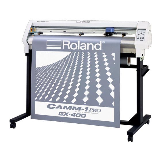
Roland Camm-1 Pro GX-500 User Manual

Roland Camm-1 Pro GX-500 User Manual

Sign maker
Hide thumbs Also See for Camm-1 Pro GX-500:

Advertisement

Thank you very much for purchasing the GX-500/400/300.
To ensure correct and safe usage with a full understanding of this product's
performance, please be sure to read through this manual completely and store
it in a safe location.
Unauthorized copying or transferral, in whole or in part, of this manual is
prohibited.
The contents of this operation manual and the specifications of this product
are subject to change without notice.
The operation manual and the product have been prepared and tested as much
as possible. If you find any misprint or error, please inform us.
Roland DG Corp. assumes no responsibility for any direct or indirect loss or
damage which may occur through use of this product, regardless of any failure
to perform on the part of this product.
Roland DG Corp. assumes no responsibility for any direct or indirect loss or
damage which may occur with respect to any article made using this product.

Advertisement

Table of Contents
loading

Summary of Contents for Roland Camm-1 Pro GX-500

  • Page 1 If you find any misprint or error, please inform us. • Roland DG Corp. assumes no responsibility for any direct or indirect loss or damage which may occur through use of this product, regardless of any failure to perform on the part of this product.
  • Page 2 AVIS Cet appareil numérique de la classe A respecte toutes les exigences du Règlement sur le matériel brouilleur du Canada. ROLAND DG CORPORATION 1-6-4 Shinmiyakoda, Hamamatsu-shi, Shizuoka-ken, JAPAN 431-2103 MODEL NAME : See the MODEL given on the rating plate.
  • Page 3: Table Of Contents

    8-3 Error Messages ........................ 74 9 Specifications .......................... 75 9-1 Locations of the Power Rating and Serial Number Labels ..........75 9-2 Specifications ........................76 9-3 Interface Specifications ..................... 78 CutStudio™ is trademark of Roland DG Corporation. Copyright © 2007 Roland DG Corporation http://www.rolanddg.com/...
  • Page 4: To Ensure Safe Use

    To Ensure Safe Use Improper handling or operation of this machine may result in injury or damage to property. Points which must be observed to prevent such injury or damage are described as follows. About WARNING and CAUTION Notices Used for instructions intended to alert the user to the risk of death or severe WARNING injury should the unit be used improperly.
  • Page 5 To Ensure Safe Use Incorrect operation may cause injury WARNING CAUTION Be sure to follow the operation proce- Exercise caution to avoid being pinched dures described in this documentation. or becoming caught. Never allow anyone unfamiliar with the Inadvertent contact with certain areas may cause usage or handling of the machine to touch the hand or fingers to be pinched or become caught.
  • Page 6 Never use in any location where use if any component is damaged. gases can accumulate. Continuing to use the machine may result in fire, Combustion or explosion may be a danger. electrical shock, or injury. Contact your autho- rized Roland DG Corp. dealer.
  • Page 7 To Ensure Safe Use Important notes about the power cord, plug, and electrical outlet Never place any object on top or subject to Never allow to get wet. damage. Never bend or twist with undue force. Never make hot. Never pull with undue force. Dust may cause fire.
  • Page 8 To Ensure Safe Use Warning Labels Warning labels are affixed to make areas of danger immediately clear. The meanings of these labels are as follows. Be sure to heed their warnings. Also, never remove the labels or allow them to become obscured. Caution: Moving Carriage The cutting carriage moves at high speed and pose a hazard.
  • Page 9 To Ensure Safe Use...
  • Page 10: Pour Utiliser En Toute Sécurité

    Pour utiliser en toute sécurité La manipulation ou l'utilisation inadéquates de cet appareil peuvent causer des blessures ou des dommages matériels. Les précautions à prendre pour prévenir les blessures ou les dommages sont décrites ci-dessous. Avis sur les avertissements Utilisé pour avertir l'utilisateur d'un risque de décès ou de blessure grave en ATTENTION cas de mauvaise utilisation de l'appareil.
  • Page 11 Pour utiliser en toute sécurité L'utilisation incorrecte peut causer des blessures ATTENTION PRUDENCE S'assurer de suivre les procédures Faire preuve de prudence pour éviter d'utilisation décrites dans la documenta- l'écrasement ou le coincement. tion. Ne jamais permettre à quiconque ne La main ou les doigts peuvent être écrasés ou connaît pas le fonctionnement ou la coincés s'ils entrent en contact avec certaines...
  • Page 12 Continuer à utiliser l'appareil peut causer un de produit inflammable en aérosol à incendie, un choc électrique ou des blessures. proximité de l'appareil. Ne jamais utiliser Communiquer avec le représentant Roland DG l'appareil dans un endroit où des gaz Corp. Autorisé. peuvent s'accumuler.
  • Page 13 Pour utiliser en toute sécurité Remarques importantes à propos du câble d'alimentation, de la fiche et de la prise électrique Ne jamais déposer aucun objet sur le câble, sur la fiche Ne jamais laisser l'eau toucher le câble, la ou sur la prise car cela risque de les endommager. fiche ou la prise.
  • Page 14 Pour utiliser en toute sécurité Vignettes d'avertissement Des vignettes d'avertissement sont apposées pour qu'il soit facile de repérer les zones dangereuses. La signification des vignettes est donnée ci-dessous. Respecter les avertissements. Ne jamais retirer les vignettes et ne pas les laisser s'encrasser. Attention : Chariot mobile Le chariot de coupe se déplace très rapidement et peut être dangereux.
  • Page 15: Important Notes On Handling And Use

    Important Notes on Handling and Use This machine is a precision device. To ensure the full performance of this machine, be sure to observe the following important points. Failure to observe them may not only result in loss of performance, but may also cause malfunction or breakdown. Main unit This Machine Is a Precision Device ➢Handle carefully, and never subject the machine to impact or excessive force.
  • Page 17: Checking Supplied Items

    Power cord Blade Alignment tool (XD-CH2) CD-ROM Replacement blade Cable clamp (Roland Software Package) for separating knife USB cable User’s Manual (this document) Setup Guide Part Names and Functions * The figure shows the GX-500 installed with the PNS-502 special stand.
  • Page 18: Rear View

    2-2 Rear View Sheet Loading Lever These raise and lower the Tray pinch rollers. Use this to store blades. Power Connector Connect the power cord included with the machine to this connector. USB Connector This is for connecting a computer with a USB cable. Sheet Sensor Brake Serial Connector...
  • Page 19: Basic Operation

    Basic Operation 3-1 Loading the Material (Roll Material) Roll material must be placed at a predetermined shaft position. Failure to do so may result in falling of the roll, leading to injury. Acceptable Material Width and Maximum Cutting Width Acceptable material widths Maximum cutting width GX-500 Min.90 mm (3-1/2 in.)
  • Page 20 Loading Roll Material * When performing lengthy cutting of 1.5 m (60 in.) or more, please refer to the section “4-3 To Perform Lengthy Cutting”. For information on how to install the sheet hangers, shafts, brake, and stoppers, please refer to the “ASSEMBLY INSTRUCTIONS” for the PNS-502/402/302 (the stand for the GX-500/400/300).
  • Page 21 Using the grit marks as a reference, position the material so that its right edge lies over the right grit roller and its left edge simultaneously lies over any of the other grit rollers. Grit marks These indicate the position of the grit rollers. Grit rollers Grit roller (Right) Material...
  • Page 22 GX-400 Material Loading Position : Grit Roller : Movable Pinch Roller (Middle) : Movable Pinch : Movable Pinch Roller (Left) Roller (Right) 6 in.(approx. 152 mm) 12 in. (approx. 305 mm) Material 18 in. (approx. 457 mm) 24 in. (approx. 610 mm) 30 in.
  • Page 23 GX-300 : Grit Roller Material Loading Position : Movable Pinch : Movable Pinch Roller (Left) Roller (Right) 6 in.(approx. 152 mm) 12 in. (approx. 305 mm) Material 18 in. (approx. 457 mm) 24 in. (approx. 610 mm) 30 in. (approx. 762 mm) The right-hand movable pinch roller can be moved within this range.
  • Page 24 Pull out material toward the front, position it in place so that it is lined up straight with the guide lines, then move the left and right pinch rollers to position them above the grit rollers. Position the middle pinch roller at the center between the left and right pinch rollers. If a grit mark is present between the left and right pinch rollers, position the middle pinch roller above the corresponding grit roller.
  • Page 25: Installing A Blade

    POWER LED lights up Switch on the power. At [SELECT SHEET], use the [ ] and [ ] keys SELECT SHEET to select [ROLL], then press the [ENTER] key. *ROLL For more information about selecting material, see “4- 2 Details of the Origin-point Location and Cutting Area.”...
  • Page 26: Adjusting The Blade Force And Cutting Speed

    Tighten the cap all the way. (1) Loosen the tool securing screw on the tool carriage. Tool carriage (2) Support the tool securing screw from below and install the blade holder. Insert the blade holder Tighten until the collar is flush with the carriage. (3) Tighten the tool securing screw until the blade Loosen holder is secured in place.
  • Page 27 (1) Peel off the round section (marked by Check the state of cutting. When it can be peeled by itself, without disturbing the square (marked by ), the blade force is set appropriately. (2) Remove the square section (marked by The optimum blade pressure is correct if you can clearly make out the lines left by the blade.
  • Page 28: Setting The Origin Point

    Adjusting the Cutting Speed Examine the results of the cutting test and adjust the cutting speed accordingly. Press the [SPEED] key to display the screen in the SPEED 20cm/s figure. *20cm/s Cutting-speed adjustment Setting range: 1 to 85 cm/s (settable in increments of 1 cm/s) Use the [ ] and [...
  • Page 29: Starting Cutting

    3-5 Starting Cutting Material Test Feed Perform test feed beforehand to ensure that the roll material is not pulled with undue force during cutting. If the roll material is pulled with undue force during cutting, a motor error may occur, or the position may be displaced. Test feed can also be performed to make sure that the loaded material is straight.
  • Page 30 Downloading Cutting Data Cutting starts when the machine receives cutting data sent from the computer. NOTICE If the material becomes dislodged or there is a problem in operation, then immediately press the [PAUSE] key or turn off the power switch on the right side of the machine. The CAMM-1 driver is necessary to perform cutting with this machine using data created by another program.
  • Page 31 To Change the Cutting Speed or Blade Force During Cutting If you change the cutting speed or blade force during cutting, carry out the operation described below. Press the [PAUSE] key. CONTINUE PAUSE The cutting operation pauses and the screen shown in STOP ENTER the figure appears.
  • Page 32: When Cutting Is Completed

    3-6 When Cutting is Completed When not in use for extended periods, unplug the power cord from the electrical outlet. Failure to do so may result in danger of shock, electrocution, or fire due to deterioration of the electrical insulation. NOTICE Never leave the tool securing screw tightened.
  • Page 33: Advanced Operation

    Advanced Operation 4-1 Detailed Cutting-condition Settings Adjusting the Blade Extension When you want to perform accurate and fine adjustment of the cutting-in amount, such as when cutting material with thin carrier paper or when performing half-cutting of material having no carrier paper, you can obtain good results by adjusting the tip of the blade.
  • Page 34 Press the [ ] key. FORCE 50gf Press the [ ] key. Press the [ ] several times. OFFSET 0.250mm Press the [ ] key. OFFSET 0.250mm Use the [ ] and [ ] key to set the value. *0.275mm Blade-offset adjustment Setting range: 0 to 1.000 mm (in increments of...
  • Page 35 Press the [ ] key several times. UPSPEED AUTO Press the [ ] key. UPSPEED AUTO Use the [ ] and [ ] keys to enter the up speed. *50cm/s Adjusting the Up Speed Setting range: AUTO, 10 to 50 cm/s (in increments of 10 cm/s) Press the [ENTER] key to enable the up speed.
  • Page 36: Details Of The Origin-Point Location And Cutting Area

    4-2 Details of the Origin-point Location and Cutting Area The Location of the Origin Point Immediately After Loading Material With this machine, the initial origin point is determined when you load material and press the [ENTER] key. This origin point differs according to the selection made for [SELECT SHEET] on the operation panel when loading material.
  • Page 37 The Location of the Origin Point Immediately After Loading Ma- terial (When [ROTATE] is set to [0deg]) “ROLL” (When using roll material) The origin point is set at the location where the material is loaded, near the left pinch roller. Material Pinch Roller (0.0)
  • Page 38 Coordinate Rotation Settings This rotates the cutting coordinates by 90 degrees. The default setting is at [0deg], and the origin point is set at the lower left of the material. Setting this to [90deg] set the origin point at the lower right of the material and rotates the text (or graphics) by 90 degrees. * Note that the coordinate axes change when rotated.
  • Page 39: To Perform Lengthy Cutting

    About the Cutting Area The cutting area along the horizontal plane (the direction in which the tool carriage moves) is determined by the position of the pinch rollers. The workable area spans the length between the two rollers, minus a margin of about 1 mm (about 0.04 in.) on both sides. If the material length is greater than 1,600 mm (63 in.) when a flat material has been loaded, this machine determines it to be a roll material and sets the material length to 24,998 mm (984-1/8 in.).
  • Page 40 Pull out the material from the roll and pass it through the unit. Stretch taut, with no slackness. Position the left and right pinch rollers as shown in the figure, and position the middle pinch roller at the center between the left and right pinch rollers.
  • Page 41: Loading Flat Material (Standard-Size Material, Cut Material, Etc.)

    Use the operation panel as follows to perform test feed for the material. The material is fed out by the set length. Make sure the material is not crooked. If the material is crooked and looks like it might come loose from the pinch rollers, press the [PAUSE] key, then hold down the [ENTER] key for 0.5 seconds or longer to stop material feed.
  • Page 42: Repeating The Same Cutting

    If a pinch roller is positioned over an area where there is no grit roller, the BAD POSITION message shown in the figure appears when you press the [ENTER] key. If this occurs, lower the sheet loading levers and move the pinch rollers to the proper positions above the grit rollers.
  • Page 43: Front Loading

    4-6 Front Loading You can use the front-loading feature of this machine, which lets you load roll material at the front of the machine, by installing the sheet hangers on the front. Installing the Sheet Hangers Install the sheet hangers on the front of the machine. For an explanation of how assemble the unit and the stand (PNS-502/402/302), refer to the “ASSEMBLY INSTRUC- TIONS”...
  • Page 44 About the Origin Point and the Cuttable Area For front loading, the [SELECT SHEET] setting made when you load the material must be set to either [ROLL] or [R-EDGE]. The origin-point location and the area where cutting is possible are as shown below. (The figure shows the case where [ROTATE] is set to [0 deg].) [ROLL] [R-EDGE]...
  • Page 45 Press the [MENU] key to back to the screen shown in 20cm/s the figure. 50gf 0.250mm A If the material is crooked and looks like it might come loose from the pinch rollers, or actually does come loose, reload the material. In addition to the preceding method, you can also set the origin point by using the [ ] and [ ] keys to feed out the...
  • Page 46: The Overcut Feature

    4-7 The Overcut Feature This cuts an excess margin of 1 mm (0.04 in.) from the first and last line segments. This is effective when you want to finish with angles that are especially sharp, such as when cutting thick material. This should normally be left set at [DISABLE].
  • Page 47: The Memory Feature

    4-8 The Memory Feature With this machine, you can set and store eight types of cutting conditions for different tools and materials. You can call up the settings simply by using the [MEMORY] key. To Store in Memory Use the display menu to make the settings for cutting conditions matched to the tool and material in use. You can set the following five types of parameters.
  • Page 48 Calling Up Press the [MEMORY] key. Use the [ ] and [ ] keys to select the user number LOAD *USER1 you want to call up. The parameters set to the selected 20-50-0.250 user number appear on the display. Speed - Force - Offset Press the [ENTER] key.
  • Page 49: The Crop Mark Feature

    Using the Included Program Using the included Roland CutStudio program enables you to print, together with the image, crop marks that the machine's sensors can automatically detect, then perform alignment automatically and carry out cutting. For information on how to perform this operation, see the electronic-format manual (“Printing and Cutting Guide”...
  • Page 50 2. Get ready to perform cutting. When you have completed the figure data containing crop marks, print the material. Load the material (printed with a figure), and install the included alignment tool (see “3-1 Loading the Material,” “3-2 Installing a Blade,”...
  • Page 51 4. Perform cutting. First use the alignment tool to line up the tip of the alignment tool with the leading edge of the crop marks, then send the cutting data. Press the [ ] key. MANUAL Use the [ ] and [ ] keys to select either [4-POINT 4-POINT START START] or [3-POINT START], then press the...
  • Page 52 Press the [ENTER] key COMPLETED ENTER The screen shown in the figure appears. STOP MENU When you've finished making the settings, then to perform cutting, press the [ENTER] key. * Pressing the [MENU] key cancels the settings and 20cm/s returns you to the screen shown in the figure. 50gf 0.250mm Make sure that the screen shown in the figure flashes, OUTPUT DATA...
  • Page 53: Performing Test Feed Of Material

    4-10 Performing Test Feed of Material Automatically This makes the setting for performing test feed of the material automatically before cutting starts. It is intended to prevent motor errors or misalignment due to roll material being pulled out at the feed rate used during cutting. The test feed is performed for the required distance as determined by the size of the cutting data.
  • Page 55: Selecting The Material And Blade

    Selecting the Material and Blade 5-1 Material and Blade Combinations The table below is a general guide to suitable blades and cutting conditions for various types of material, as well as to blade lifespan and other values under the respective conditions. Refer to it when selecting the material and blade. Cutting conditions and blade life vary according to the hardness of the material and the usage environment.
  • Page 56: About Special Materials

    5-2 About Special Materials This section describes some tips and important notes when using special materials with this unit. Note, however, that depending on various factors or the usage environment, the use of some materials with this unit may not be possible. Before actual use, carry out test feed and a cutting test to make sure the material is suitable for use with this unit.
  • Page 57: Descriptions Of Features

    Descriptions of Features 6-1 Key Operations This describes the key operations. Refer to this together with the display-menu flowcharts on the following pages to make settings using the menus. Direct Keys [MEMORY] [FORCE] [SPEED] Pressing any one of these three keys displays the setting screen. Use [ ] and [ ] to change the setting value, then press [ENTER] to enable the setting.
  • Page 58: Display Menus Flowchart

    6-2 Display Menus Flowchart For details about each of the menus, see “6-3 List of Functions.” Power ON GX-500 Roland DG Corp. Select sheet SELECT SHEET * ROLL < ROLL, F-EDGE, R-EDGE, PIECE > ENTER NOW LOADING • • • • •...
  • Page 59 Continue Continue Only when the [AUTO / SERIAL] is selected, it is possible to set. to [HAND] I/O AUTO BAUD 9600 BAUD 9600 < AUTO > * AUTO * 9600 < AUTO/USB/SERIAL > DATA 8 DATA 8 STOP 1 STOP 1 PARITY NONE PARITY NONE NONE...
  • Page 60 Continue Continue to [CALIB] OTHERS SMOOTHING ON SMOOTHING ON * ON UNIT mm UNIT mm * mm FACTORYDEFAULT FACTORYDEFAULT * PRESET SELF TEST CONTRAST 5 CONTRAST 5 TEST PATTERN TYPE 1 TEST PATTERN TYPE 1 * TYPE 1 OVER CUT DISABLE OVER CUT DISABLE * DISABLE to [CALIB Y]...
  • Page 61: List Of Functions

    6-3 List of Functions Control-key Functions This describes the functions of the control keys when pressed. Function Range Default MEMORY This calls up user-set cutting conditions matched to the USER1 to 8 – tool and material in use. FORCE This sets the force for the blade during cutting. 20 to 350 gf 50 gf Perform a cutting test and set the conditions to match...
  • Page 62 Description of Menu Items This describes the items and functions available when you press [MENU] and enter the menu mode. Menu Function Range Default UNSETUP This cancels material setup (unsetup). – – CONDITION FORCE This sets the force of the blade when the material is cut. 20 to 350 gf 50 gf Make the setting suitable for the material and the blade...
  • Page 63 Menu Function Range Default This makes the setting for the type of interface used AUTO/ AUTO for connection to the computer. This is normally set to USB/ [AUTO]. SERIAL This machine cannot use two ports concurrently. When set to [AUTO], the first port that receives data after the power is turned on is selected as the usable port.
  • Page 64 Menu Function Range Default SETTING VS CMD To perform cutting at the speed determined by a VS DISABLE/ENABLE DISABLE COMMANDS command (tool speed setting command) sent from the computer, set this to [ENABLE]. When set to [DISABLE], cutting is performed using the values for [**cm/s] at the cutting conditions screen and [UPSPEED].
  • Page 65 Menu Function Range Default OVER This cuts an excess margin of 1 mm (0.04 in.) from the DISABLE/ENABLE DISABLE first and last line segments. This selection is normally set to [DISABLE], and is set to [ENABLE] when cutting especially attractive corners is desired.
  • Page 67: Maintenance

    Maintenance 7-1 Cleaning NOTICE Always turn off this machine before cleaning it. Never lubricate the mechanisms. Do not clean with solvents (such as benzine or thinner). [Cleaning the body] Use a cloth moistened with water then wrung well, and wipe gently to clean.
  • Page 68: Consumable Items

    Performing cutting with a damaged blade protector may make attractive cutting impossible. When the surface of the blade protector is deformed by scratching or the like, it is necessary to replace the blade protector. Contact your authorized Roland DG Corp. dealer.
  • Page 69: How To Replace The Separating Knife

    7-3 How to Replace the Separating Knife Make sure the power to the unit is off before attempting to replace the separating knife. Doing so may result in injury. If the separating knife is not sharp enough to cut attractively, replace it with the replacement knife included with this machine. Follow the steps below to replace the knife.
  • Page 71: If There Is A Problem

    If There Is a Problem 8-1 Self-test Operation Check This machine is provided with a self-test feature for verifying that operation is correct. If this machine does not operate correctly, follow the steps below to check its operation. (No computer is required to perform an operation check.) Refer to “3-1 Loading the Material (Roll Material)”...
  • Page 72: What To Do If

    8-2 What to do if... GX-500/400/300 Troubleshooting Is the power cord connected correctly? Connect the power cord bundled to the machine, and plug the other end securely into an electrical outlet. Is the machine power on ? Turn on the power. Is the machine in the temporary halt If the screen shown in the figure is displayed, CONTINUE...
  • Page 73 A message appears on the display The location of one or more of the pinch rollers is not correct. BAD POSITION Press the [ENTER] key to clear the error, then reload the material correctly. (Refer to “3-1 Loading the Material (Roll Material).”) This is displayed when the material has been loaded at a position where the SHEET UNLOADED sheet sensor does not function.
  • Page 74 Cut lines are uneven or not cut attractively Are the blade and blade holder installed Install them tightly enough not to loose (see “3-2 Installing a Blade.” ) correctly and securely ? Are there material debris in the blade Remove the cap from the blade holder and clean out the debris. (Refer to “7-1 holder? Cleaning.”) Is a thick material being used?
  • Page 75 If the material comes loose even when it is loaded correctly, the useful life of the deformed? pinch rollers has ended. If this happens, contact your authorized Roland DG Corp. dealer. Also, when you are not performing cutting, leave the sheet loading levers lowered...
  • Page 76: Error Messages

    8-3 Error Messages An error message will appear if incoming data has any of the errors listed in table. However, the error is shown in the display for informational purposes, the data transfer continues and you are allowed to perform the next operation. To clear the display, press any key.
  • Page 77: Specifications

    Specifications 9-1 Locations of the Power Rating and Serial Number Labels Serial Number This is required when you seek mainte- nance, servicing, or support. Never peel off the label or let it get dirty. Power Rating Use an electrical outlet that meets the requirements for voltage, frequency, and amperage given here.
  • Page 78: Specifications

    Power cord, blade holder (XD-CH2), pin, blade, alignment tool, cable clamp, replacement blade for separating knife, USB cable, Roland software package CD-ROM, setup guide, user’s manual According to material and cutting conditions as specified by Roland DG Corp. (refer to the following page). Excluding stretching/contraction of the material Range for assured repetition accuracy For materials with a width exceeding 610 mm (24 in.): Length 4,000 mm (157-7/16 in.) (GX-500/400 only)
  • Page 79 The following conditions must be satisfied: • Material type: 3M Scotchcal Mastercut • Special stand (a roll material must be set at the rear and on the sheet hanger) • Side margins: 25 mm (1 in.) or more for both the left and right margins •...
  • Page 80: Interface Specifications

    Pin #4 [XY-RS-34 serial cable connection] Note: When making a serial connection using a cable other than a XY-RS-34 cable from Roland DG Corp., use a serial cable wired as shown in the figure below. D-sub 9-pin (female) D-sub 25 pin (male)
  • Page 84 R3-070216...

This manual is also suitable for:

Camm-1 pro gx-400Camm-1 pro gx-300

Table of Contents