Table of Contents
Advertisement
Quick Links
Advertisement
Table of Contents

Subscribe to Our Youtube Channel
Related Manuals for Keysight 34959A


Summary of Contents for Keysight 34959A
- Page 1 Keysight 34959A Breadboard Module User’s Guide...
- Page 2 OR OF ANY INFORMATION Edition forth therein, does not require or CONTAINED HEREIN. SHOULD permit, among other things, that KEYSIGHT AND THE USER HAVE A Edition 3, July 1, 2019 Keysight: (1) Furnish technical SEPARATE WRITTEN AGREEMENT Printed in: information related to commercial...
-
Page 3: Safety Symbols
Frame or chassis (ground) terminal Standby supply. Unit is not completely disconnected from ac mains when Caution, risk of electric shock switch is off Caution, risk of danger (refer to this manual for specific Warning or Caution information) Keysight 34959A User’s Guide... -
Page 4: Additional Safety Notices
Failure to comply with these precautions or with specific warnings or instructions elsewhere in this manual violates safety standards of design, manufacture, and intended use of the instrument. Keysight Technologies assumes no liability of the customer’s failure to comply with the requirements. -
Page 5: Do Not Remove The Instrument Cover
Do Not Modify the Instrument Do not install substitute parts or perform any unauthorized modification to the product. Return the product to an Keysight Sales and Service Office for service and repair to ensure that safety features are maintained. In Case of Damage... -
Page 6: Waste Electrical And Electronic Equipment (Weee) Directive 2002/96/Ec
To return this unwanted instrument, contact your nearest Keysight Service Center, or visit http://about.keysight.com/en/companyinfo/environment/takeback.shtml for more information. Sales and Technical Support To contact Keysight for sales and technical support, refer to the support links on the following Keysight websites: – www.keysight.com/find/34980a (product-specific information and support, software and documentation updates) –... -
Page 7: Table Of Contents
34959A Breadboard Module Disassembly ..... . .11 34959A Breadboard Module Layout (shown with cover removed) ..13 Ribbon Cable Header Pin Assignment Information . - Page 8 THIS PAGE HAS BEEN INTENTIONALLY LEFT BLANK. Keysight 34959A User’s Guide...
-
Page 9: 34959A Breadboard Module Description
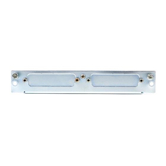
34959A Breadboard Module Description The 34959A Breadboard Module provides a 137mm x 190mm x 23mm (5.4” x 7.5” x 0.9”) space inside the 34980A Multifunction Switch/Measure Unit, for you to install custom circuitry to support applications not available on the standard plug-in modules. - Page 10 34959A Bread board Simplified Block Diagram Custom PC Board 34980A Mainframe 34959A Bread board PC Board 34980A Analog Bus Analog Relays (4) Buses (user installed) 4 (2-wire) Ribbon ABus Relay Drives Custom Cable Connector (Ch 911-914) Circuitry (P101) Field Relay Drives...
-
Page 11: 34959A Breadboard Module Disassembly
DB50/DB78 port covers The Keysight-supplied PC board must be removed if you are making connections to the Analog Buses, in order to solder the necessary relays (not provided) and lead wires. To remove this PC board, remove the Torx T10 screw shown, slide the cover back 5mm to clear the two retaining tabs, and lift the board up. - Page 12 Removal of the Keysight-Supplied PC Board Torx T10 Screw Retaining Slide Keysight-supplied PC board back 5mm to clear retaining tabs and lift up Keysight 34959A User’s Guide...
-
Page 13: 34959A Breadboard Module Layout (Shown With Cover Removed)
34959A Breadboard Module Layout (shown with cover removed) Analog Bus relay and Connector to connection area 34980A backplane Keysight-supplied PC board Ribbon cable Ribbon cable header P101 header P102 Ribbon cable headers (for connecting custom circuitry) Space for mounting custom circuitry... -
Page 14: Ribbon Cable Header Pin Assignment Information
Ribbon Cable Header Pin Assignment Information The 34959A breadboard is supplied with two ribbon cable headers, which may be used to access 5V and 12V power, open/close four Analog Bus channels, open/ close up to 28 customer-supplied general-purpose relays (up to 100 mA sink to ground), and utilize two 8-bit banks of digital I/O. - Page 15 Channel 911 (dual-purpose relay drive∗) reserved - do not connect to this pin Channel 128 (gen. purpose relay drive) Channel 116 (gen. purpose relay drive) Channel 127 (gen. purpose relay drive) Channel 115 (gen. purpose relay drive) Keysight 34959A User’s Guide...
- Page 16 Analog Buses 1-4 and equipment damage may result from making connections to pins 1 through 4 of P101. Otherwise, channels 911-914 and pins 1-4 may be used as four additional general purpose relay drive lines. Keysight 34959A User’s Guide...
-
Page 17: Configuring The 34959A Breadboard Module
SHOCK HAZARD Only qualified personnel who are aware of the hazards WARNING involved should install, remove or configure the 34959A breadboard for the 34980A mainframe. Before touching any installed accessory, turn off all power to the mainframe and terminal blocks, and to all external devices connected to the mainframe or terminal blocks. - Page 18 The connections from the Analog Bus outputs (8 holes marked on the Keysight-supplied PC board as 1 through 4, H and L) to your custom circuitry should be made with wire insulated for 300V service.
-
Page 19: Installing Custom Circuitry On The 34959A Breadboard Module
SHOCK HAZARD If any of the relays K101-K104 are installed on the 34959A WARNING module’s Keysight-supplied PC board then an Analog Bus connection is possible to other installed plug-in modules. This connection can present hazardous voltages (up to 300V) to the user’s custom PC board installed on the 34959A or any attached test circuitry. - Page 20 40-conductor ribbon cable 971111-5 PC-board mount 4-216093-0 The suggested suppliers for these cables and connectors are: Vendor: 3M Corporation Vendor Address: 6801 River Place Boulevard, Austin, TX 78726 U.S.A. Vendor: Vendor Address: Harrisburg, PA 17105 U.S.A. Keysight 34959A User’s Guide...
- Page 21 300V potentials available on the breadboard’s Analog Bus connectors. Spacing and Insulation Requirements for High Voltage Applications If your planned use of the 34959A breadboard module will involve the application of high voltages (>30V AC or >60V DC), refer to appropriate electrical standards for high-voltage circuit spacing and wire insulation requirements.
-
Page 22: Operating Considerations
Pollution Degree Levels 1, 2 and 3. Operating Considerations Electrical Specifications The specifications below were derived from the individual components used to provide the relay drive and digital I/O functions: Electrical Specifications for the 34959A Bread board Mod ule Specification Test Cond itions Minimum Typical... - Page 23 The maximum recommended power consumption/dissipation for the breadboard module and its installed circuitry is 6 watts, resulting in a 5 C rise in temperature. To allow adequate cooling of the breadboard module, ensure that your circuit NOTE layout does not impede air flow. Keysight 34959A User’s Guide...
-
Page 24: Dimension Information For The Custom Pc Board Area
Dimension Information for the Custom PC Board Area Utilization of the empty space within the 34959A breadboard module is left entirely up to the user. However, assuming you want to most fully utilize the space provided, output signals through the Dsub ports, and connect your board securely to the supplied ribbon cable headers, four detailed dimension drawings are provided in this section to assist with your PC board fabrication. - Page 25 Footprint for mounting 50-pin Dsub connectors shown Pin 1 Pin 1 Dimension “A” DATUM Clearance to sheet metal Dimension “A” DB-50 (M/F): 10.38mm All d imensions are DB-78 (M): 12.25mm shown in millimeters DB-78 (F): 10.87mm Keysight 34959A User’s Guide...
- Page 26 PC Board Footprint of Suggested DB50 Connectors (M/F) All Dimensions are shown in millimeters Keysight 34959A User’s Guide...
- Page 27 PC Board Footprint of Suggested DB78M Connector All Dimensions are shown in millimeters PC Board Footprint of Suggested DB78F Connector All Dimensions are shown in millimeters Keysight 34959A User’s Guide...
-
Page 28: Programming The 34959A Breadboard Module
Analog Bus relays K101 through K104 are installed on the 34959A, you can route external signals to the Analog Buses or access signals introduced to those buses through other installed modules. Refer to Chapter 2 for configuring the internal DMM for making voltage, resistance, or frequency measurements. -
Page 29: General Purpose Relay Functions
“Test Point A” to Analog Bus channel 913: ROUTe:CHANnel:LABel "Test Point A", (@2913) Most SCPI commands can address more than one channel at a time, including specifying a range of channels. Refer to the Keysight 34980A Programmer’s Reference for more complete information. General Purpose Relay Functions... -
Page 30: Digital I/O Functions
(indeterminate). The read timing diagram is shown on page Timing for Write Commands When the 34980A receives a SCPI command to write to the breadboard, control line 3 is set low (indicating a write request). Keysight 34959A User’s Guide... - Page 31 The write timing diagram is shown below. Timing Diagrams for the Digital Read and Write Commands The strobe timing, control line status and data timing for the read and write commands as explained above are illustrated in the diagrams that follow: Keysight 34959A User’s Guide...
- Page 32 34959A Bread board Mod ule Digital I/O Timing Diagrams Data Write data from 34959A μ data to write 1.25 data hold till next read or write μ write to strobe 1.25 μ write to strobe 1.25 read/write μ strobe width 1.25...
- Page 33 SENSe:DIGital:DATA:WORD? (@4001) Example: If the Breadboard Module is in slot 6, and channel 001 has been configured as a byte input, the following command returns the state of bit 4 on the channel 001 byte: SENSe:DIGital:DATA:BIT? 4,(@6001) Keysight 34959A User’s Guide...
- Page 34 To output a digital byte, the specified value may be binary (valid values from #B00000000 through #B11111111), hexadecimal (valid values from #H0 through #HFF) or integer (valid values 0 through 255) and the syntax is: SOURce:DIGital:DATA:BYTE <data>, (@<ch_list>) Keysight 34959A User’s Guide...
- Page 35 Example: If the Breadboard Module is in slot 8, and channels 001 and 002 have been configured as a word output, any of the following commands will write the value 1001100110011001 to the combined digital channel: SOURce:DIGital:DATA:WORD #B1001100110011001,(@8001) SOURce:DIGital:DATA:WORD #H9999,(@8001) SOURce:DIGital:DATA:WORD 39321,(@8001) Keysight 34959A User’s Guide...
- Page 36 THIS PAGE HAS BEEN INTENTIONALLY LEFT BLANK. Keysight 34959A User’s Guide...
- Page 37 I/O command timing dimensions for the custom PC board area disassembly Dsub connector recommendations electrical specifications installing custom circuitry layout of the module programming examples ribbon cable pinouts safety notices simplified block diagram Keysight 34959A User’s Guide...
- Page 38 THIS PAGE HAS BEEN INTENTIONALLY LEFT BLANK. Keysight 34959A User’s Guide...
- Page 39 This information is subject to change without notice. Always refer to the Keysight website for the latest revision. © Keysight Technologies 2008-2019 Edition 3, July 1, 2019 Printed in Malaysia *34980-90059* 34980-90059 www.keysight.com...
Need help?
Do you have a question about the 34959A and is the answer not in the manual?
Questions and answers