
Related Manuals for Siemens FN2013-U1


Summary of Contents for Siemens FN2013-U1
- Page 1 FN2013-U1, FN2014-U1 Fiber network module (SM/MM) Installation Mounting Smart Infrastructure A6V12093642_en--_b 2023-01-23...
- Page 2 Issued by: Siemens Industry, Inc. Smart Infrastructure 2 Gatehall Drive Parsippany, NJ 07054 Tel. +1 973-593-2600 www.usa.siemens.com/fire Edition: 2023-01-23 Document ID: A6V12093642_en--_b © Siemens Industry, Inc., 2021 2 | 28 2023-01-23 A6V12093642_en--_b...
-
Page 3: Table Of Contents
Table of contents Fiber network module FN2013 / FN2014 ............ Description ..................... Installation in Desigo/CerberusPRO Modular..........Views......................Wiring ......................1.4.1 Wiring for Desigo/Cerberus PRO Modular ........1.4.2 Power supply sockets (4, 6) ............. 1.4.3 Sockets for HNET, XNET, HUB-4, SNC (7, 8) ......... Indicators...................... - Page 4 Index of figures Fig. 1 Mounting of fiber network module with COM-BRK in housing CAB-1/-2/-3 ..........Fig. 2 Views of the fiber network module from above and the side..............Fig. 3 Class B, HNET/XNET wiring on NIC-C ....................Fig. 4 Class X, HNET/XNET wiring on NIC-C (two FN2013/FN2014 required) ..........
-
Page 5: Fiber Network Module Fn2013 / Fn2014
Fiber network module FN2013 / FN2014 Description 1 Fiber network module FN2013 / FN2014 1.1 Description The fiber network module multi-mode (MM) and the fiber network module single-mode (SM) can be used for the exclusive purpose of networking fire detection panels to the HNET, XNET, SNC, or HUB-4 over large distances using fiber-optic cable. The fiber network modules have the following features: ●... -
Page 6: Fig. 1 Mounting Of Fiber Network Module With Com-Brk In Housing Cab-1/-2/-3
Fiber network module FN2013 / FN2014 Installation in Desigo/CerberusPRO Modular NOTICE The fiber network module and bracket cannot be installed behind a FCM2041-U2, FCM2041-U3, LVM or FMT. NOTICE Only use the fiber network module in dry rooms. Fig. 1: Mounting of fiber network module with COM-BRK in housing CAB-1/-2/-3 Fiber network module COM-BRK mounting plate 6 | 28... -
Page 7: Views
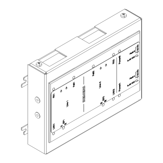
Fiber network module FN2013 / FN2014 Views 1.3 Views Fig. 2: Views of the fiber network module from above and the side Fiber-optic SC connection for circuit 1 Fiber-optic SC connection for circuit 2 10 LED indicators for data transmission, errors and power supply for both channels Power B socket, do not use Fastening tab for housing mounting... -
Page 8: Wiring
Fiber network module FN2013 / FN2014 Wiring 1.4 Wiring 1.4.1 Wiring for Desigo/Cerberus PRO Modular ● In Desigo/Cerberus PRO Modular systems, 'Power B' connections to the fiber module and monitoring of its trouble contacts are not required, as the fiber modules must be installed in the same enclosure as the power supplies that provide power to them. -
Page 9: Fig. 3 Class B, Hnet/Xnet Wiring On Nic-C
Fiber network module FN2013 / FN2014 Wiring Wiring class B HNET/XNET on NIC-C FN2013 / FN2014 Line 1 SIEMENS Line 2 Power A Power B NC NC DC 24 V NIC-C ONE SLOT OF CC-5/CC-2 Fig. 3: Class B, HNET/XNET wiring on NIC-C... -
Page 10: Fig. 4 Class X, Hnet/Xnet Wiring On Nic-C (Two Fn2013/Fn2014 Required)
Fiber network module FN2013 / FN2014 Wiring Wiring class X HNET/XNET on NIC-C FN2013 / FN2014 Line 1 FN2013 / FN2014 SIEMENS Line 1 Line 2 SIEMENS Power B Power A Line 2 NC NC DC 4 2 V Power A Power B... -
Page 11: Fig. 5 Class B, Rs485/Hub-4 Fsi Wiring
Only connect to a UL864/ULC-S527 approved, power-limited, and regulated power unit, e.g., PSC-12 / PSC-12M (TB3). No EOL resistor required on NIC-C or fiber network module. Wiring class B RS485 on HUB-4 FSI FN2013 / FN2014 Line 1 SIEMENS EOLR Port 1 Port 2 Line 2 + + _... -
Page 12: Fig. 6 Class X, Rs485/Hub-4 Fsi Wiring (Two Fn2013/Fn2014 Required)
COM-2 card. If only one interface card is being used on a COM-2 card, it must be inserted into port 1 or port 3. EOLR 120 Ω, ¼ W, P/N 104-820150 Wiring class X RS485 on HUB-4 FSI FN2013 / FN2014 Line 1 SIEMENS FN2013 / FN2014 Line 2 Line 1 Power B Power A... -
Page 13: Fig. 7 Class B Wiring To An Snc (Desigo Cc/Cerberus Dms/Ncc)
EOLR 120 Ω, ¼ W, P/N 104-820150 Wiring class B to an SNC EOLR FN2013 / FN2014 Line 1 EOLR SIEMENS Line 2 Power A Power B NC NC DC 4 2 V Fig. 7: Class B wiring to an SNC (Desigo CC/Cerberus DMS/NCC) -
Page 14: Fig. 8 Class X Wiring To An Snc (Desigo Cc/Cerberus Dms/Ncc) (Two Fn2013/Fn2014 Required)
Only connect to a UL864/ULC-S527 approved, power-limited, and regulated power unit, e.g., PSC-12 / PSC-12M (TB3). EOLR 120 Ω, 1/2 W, P/N 104-820350 Wiring class X to an SNC FN2013 / FN2014 Line 1 SIEMENS FN2013 / FN2014 Line 2 Line 1 Power A Power B... -
Page 15: Power Supply Sockets (4, 6)
Fiber network module FN2013 / FN2014 Wiring RS485 ratings: - 8 V P-P, 150 mA max., - 20 ft/6 m max. in conduit, not monitored - 16 AWG max., 18 AWG min. Only connect to a UL864/ULC-S527 approved, power-limited, and regulated power unit, e.g., PSC-12 / PSC-12M (TB3). -
Page 16: Sockets For Hnet, Xnet, Hub-4, Snc (7, 8)
Fiber network module FN2013 / FN2014 Wiring Terminal block with housing 1 2 3 C NO NC Do not use! Fig. 9: Connector power A (B) Connector plug without housing Connector plug with housing Connector 360° shielding Cover cap, open NOTICE Do not use housing when installing on COM-BRK. 1.4.3 Sockets for HNET, XNET, HUB-4, SNC (7, 8) The 3-pole connectors for the HNET/XNET/HUB-4/SNC connection are supplied with the fiber network module. -
Page 17: Indicators
Fiber network module FN2013 / FN2014 Indicators Connection A1/B1(8) Designation Description HNET/XNET/HUB-4/SNC circuit 1 (-) Do not use HNET/XNET/HUB-4/SNC circuit 1 (+) Admissible cable cross-section: 16…18 AWG Connection A2/B2 (7) Designation Description HNET/XNET/HUB-4/SNC circuit 2 (-) Do not use HNET/XNET/HUB-4/SNC circuit 2 (+) Admissible cable cross-section: 16…18 AWG 1 2 3 Fig. 10: Connector EF1/EF2, FCnet/C-WEB A1/B1 (A2/B2) Connector plug without housing Connector plug with housing Connector... -
Page 18: Technical Data
Fiber network module FN2013 / FN2014 Technical data Color Function Condition Meaning Green Receiving data from fiber- Lit up Data is being received from circuit '2' optic circuit '2' Power B Green Supervision of feeding voltage Normal operation (feeding voltage for 'Power B' available) No feeding voltage or voltage below minimum input voltage (9 V) Power A... -
Page 19: Appendix
Fiber network module FN2013 / FN2014 Appendix FN2013-U1 Single mode Range: ● Fiber type 9/125 µm 131000 ft/40000 m Optical budget: ● Fiber type 9/125 µm 29 dBm ● Minimum optical attenuation 3 dBm (corresponds to a minimum fiber length of 13000 ft / 3962 m) RS485 connection Length of line: HNET, XNET (NIC-C) 2,000 ft/610 m at 19.2 kbit/s... -
Page 20: Fig. 11 Fiber-Optic Cascading (Daisy Chain)
Fiber network module FN2013 / FN2014 Appendix Fiber-optic cascading (daisy chain) Tx Rx Tx Rx Tx Rx Tx Rx Tx Rx Tx Rx Tx Rx Tx Rx Tx Rx Tx Rx FN2013/14 FN2013/14 FN2013/14 FN2013/14 FN2013/14 RS485 RS485 RS485 RS485 RS485 EOLR EOLR EOLR EOLR... -
Page 21: Fig. 12 Star-Shaped Fiber-Optic Network
Fiber network module FN2013 / FN2014 Appendix Star-shaped fiber-optic network FACP FACP FACP FACP EOLR EOLR EOLR EOLR RS485 RS485 RS485 RS485 FN2013/14 FN2013/14 FN2013/14 FN2013/14 Tx Rx Tx Rx Tx Rx Tx Rx Tx Rx Tx Rx Tx Rx Tx Rx FACP FACP FACP... -
Page 22: Integrating Fn2013/Fn2014 Into Existing D23Xx Networks
Fiber network module FN2013 / FN2014 Appendix FACP Fire control panel Management station EOLR Terminating resistor 120 Ω All modules connected via fiber-optic cables must be the same model (FN2013 or FN2014) and use the same type of fiber (multi-mode or single-mode). Mixing of module types and types of fiber is permitted on the RS485 network. -
Page 23: Fig. 14 Adding A New Panel In Cascade
Fiber network module FN2013 / FN2014 Appendix Adding a new panel to an existing cascade (daisy chain) Tx Rx Tx Rx Tx Rx Tx Rx Tx Rx Tx Rx Tx Rx Tx Rx Tx Rx Tx Rx D23XX D23XX D23XX FN2013/14 FN2013/14 RS485 RS485 RS485... -
Page 24: Fig. 15 New Panel In Existing Star-Shaped Network
Fiber network module FN2013 / FN2014 Appendix Adding a new panel to an existing star-shaped network FACP FACP FACP FACP EOLR EOLR EOLR EOLR EOLR EOLR EOLR RS485 RS485 RS485 RS485 D23XX D23XX D23XX FN2013/14 Tx Rx Tx Rx Tx Rx Tx Rx Tx Rx Tx Rx Tx Rx... - Page 25 Fiber network module FN2013 / FN2014 Appendix Fiber-optic SC connection circuit B on D23xx RS485 connection on D23xx Existing fire control panel or management station New fire control panel or management station EOLR Terminating resistor 120 Ω FN2013 or FN2014 modules have an internal 120-ohm terminating resistor at the EF1 port.
-
Page 26: Fcc Statement
FCC Statement 2 FCC Statement WARNING Installation and usage of equipment is not in accordance with instructions manual Radiation of radio frequency energy Interference to radio communications ● Install and use equipment in accordance with instructions manual. ● Read the following information. This equipment generates, uses, and can radiate radio frequency energy and if not installed and used in accordance with the instructions manual, may cause interference to radio communications. - Page 27 A6V12093642_en--_b 27 | 28...
- Page 28 Issued by Siemens Industry, Inc. Smart Infrastructure 2 Gatehall Drive Parsippany, NJ 07054 +1 973-593-2600 www.usa.siemens.com/fire © Siemens Industry, Inc., 2021 Technical specifications and availability subject to change without notice. A6V12093642_en--_b...
Need help?
Do you have a question about the FN2013-U1 and is the answer not in the manual?
Questions and answers