Table of Contents
Advertisement
Quick Links
Advertisement
Table of Contents

Related Manuals for Pepperl+Fuchs LS684 Series


Summary of Contents for Pepperl+Fuchs LS684 Series
- Page 1 FACTORY AUTOMATION MANUAL LS684* Optical Data Coupler...
- Page 2 LS684* With regard to the supply of products, the current issue of the following document is applicable: The General Terms of Delivery for Products and Services of the Electrical Industry, published by the Central Association of the Electrical Industry (Zentralverband Elektrotechnik und Elektroindustrie (ZVEI) e.V.) in its most recent version as well as the supplementary clause: "Expanded reservation of proprietorship"...
-
Page 3: Table Of Contents
LS684* Contents 1 Introduction................. 4 Content of this Document ................4 Manufacturer....................4 Target Group, Personnel ................4 Symbols Used....................5 2 Safety................... 6 Intended Use ....................6 General Safety Information ................6 3 Product Description ............9 Intended Use ....................9 Model Varieties ...................11 Displays and Operating Elements ...............12 Signaling of the Connection Status .............12 Interfaces and Connections ................14 Scope of Delivery ..................15... -
Page 4: Introduction
Attestation of conformity Certificates Control drawings Instruction manual Other documents Manufacturer Pepperl+Fuchs GmbH Lilienthalstraße 200, 68307 Mannheim, Germany Internet: www.pepperl-fuchs.com Target Group, Personnel Responsibility for planning, assembly, commissioning, operation, maintenance, and dismounting lies with the plant operator. Only appropriately trained and qualified personnel may carry out mounting, installation, commissioning, operation, maintenance, and dismounting of the product. -
Page 5: Symbols Used
LS684* Introduction Prior to using the product make yourself familiar with it. Read the document carefully. Symbols Used This document contains symbols for the identification of warning messages and of informative messages. Warning Messages You will find warning messages, whenever dangers may arise from your actions. It is mandatory that you observe these warning messages for your personal safety and in order to avoid property damage. -
Page 6: Safety
If serious faults occur, stop using the device. Secure the device against inadvertent operation. In the event of repairs, return the device to your local Pepperl+Fuchs representative or sales office. General Safety Information Class 1M laser product... - Page 7 LS684* Safety LS68*-DA-F2 Warning! Danger due to visible class 1M laser light If the laser light is pointed at people, especially in the dark, this can lead to irritation and result in the risk of an accident due to glare. If the laser light is viewed through optical instruments (magnifying glasses, microscopes, telescopes, or binoculars, etc.), it may damage the observer's eyes due to a burning lens effect.
- Page 8 User modification and or repair are dangerous and will void the warranty and exclude the manufacturer from any liability. If serious faults occur, stop using the device. Secure the device against inadvertent operation. In the event of repairs, return the device to your local Pepperl+Fuchs representative or sales office.
-
Page 9: Product Description
LS684* Product Description Product Description Intended Use The optical data coupler serves as an optical link between two Ethernet devices; ideally, one of these devices is mobile. The opening angle is optimized for operations in high-rack storage. Devices in industrial Ethernet networks (e.g., with PROFINET, EtherNet/IP, and other Ethernet protocol designs) can be connected to the optical data coupler. - Page 10 LS684* Product Description Runtime compensation Real-time Ethernet systems allow cycle times in the microsecond range. Process data is synchronized throughout the system on the basis of a distributed time signal. The transmission paths between the network devices are measured for this purpose.
-
Page 11: Model Varieties
LS684* Product Description Throughput times of the LS684 optical data coupler Effective operating Throughput time Jitter (in LS684 models distance (meters) (per direction, in µs) LS684-DA-EN/F1 150 m 2.9 µs +/- 40 ns LS684-DA-EN/F2 LS684-DA-EN/F1/35 300 m 3.4 µs +/- 40 ns LS684-DA-EN/F2/35 Table 3.1 Throughput time depending on the model type of the LS684 optical data... -
Page 12: Displays And Operating Elements
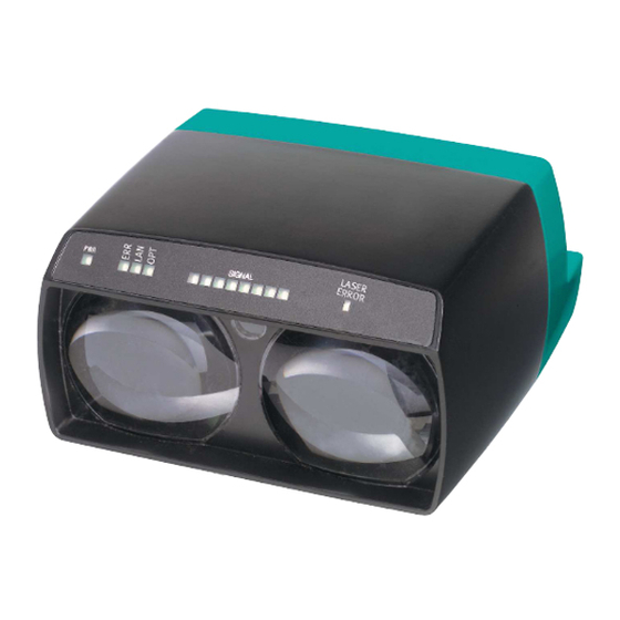
LS684* Product Description Displays and Operating Elements LASER S I G N A L ERROR Lights up as soon as the optical data coupler receives operating voltage in the correct manner. Status of the overall connection. Lights up in the event of errors (insufficient signal strength to establish the connection, e.g., misalignment, light beam obstructions, extra- neous light in the optical channel). - Page 13 LS684* Product Description If the optical data coupler detects an interruption on one of the sections, this information is displayed immediately with the status "Link Down" on both sides of the LS684 path via the Ethernet cable. As soon as the interruption is resolved, the cable connection on both sides will be restored.
-
Page 14: Interfaces And Connections
Alarm Service There is an 8-pin M12 plug on the rear of the housing for servicing. This plug is for internal use at Pepperl+Fuchs. Pinout for M12 plug, 8-pin Network A 4-pin M12 D-coded socket is located on the rear of the housing for connecting... -
Page 15: Scope Of Delivery
LS684* Product Description Pinout for M12 socket, 4-pin, D-coded Figure 3.2 Connection layout for network socket Transmit data (+) Receive data (+) Transmit data (-) Receive data (-) Scope of Delivery LS684 Package insert Accessories 3.7.1 Mounting Accessories The following mounting accessories are available: Designation Description OMH-LS610-01... -
Page 16: Network Connection Cable
LS684* Product Description Designation Description V1-G-PG9 Female single-ended cordset, straight, M12, 4-pin, field attachable V1-W-PG9 Female single-ended cordset, angled, M12, 4-pin, field attachable V1-W-2M-PVC Female single-ended cordset, angled, M12, 4-pin, PVC cable, length: 2 m V1-W-2M-PUR Female single-ended cordset, angled, M12, 4-pin, PUR cable, length: 2 m V1-W-5M-PVC Female single-ended cordset, angled, M12, 4-pin, PVC cable,... -
Page 17: Installation
2. Check the package contents against your order and the shipping documents for completeness and accuracy. Should you have any questions, direct them to Pepperl+Fuchs. 3. Retain the original packaging in case the device is to be stored or shipped again at a later date. - Page 18 LS684* Installation LS68 housing dimensions* Receiver Alignment aid Output Laser, class 1M laser product Earthing plate Socket M12 x 1, 4-pin D-coded Service Connector M12 x 1, 8-pin A-coded Power Socket M12 x 1, 4-pin A-coded Mounting using OMH-LS610-01 Caution! Danger due to inadequate operating or adjustment equipment Use of operating or adjusting equipment other than that specified here or operating and adjusting procedures other than those described in this document...
- Page 19 LS684* Installation Assembling the mounting aid and attaching the device To assemble the mounting aid and attach the optical data coupler to the adjustment device, proceed as follows: 1. Place the adjustment device on the mounting bracket in the required direction and tighten the two M4 nuts.
-
Page 20: Connection
LS684* Installation 6. Now perform the required adjustment. See chapter 5.1. 7. Once you have made the adjustments, tighten the central M6 fixing screw to fix the position in the horizontal direction. Connection Connecting the supply voltage The device conforms to protection class III. Note that the power must be supplied as a protective extra-low voltage (PELV) and must be limited according to UL Class 2 (100 W). -
Page 21: Storage And Transportation
LS684* Installation 3. Connect the other end of the grounding cable to adjacent metal components (e.g., mounting base, frame, etc.). The device is grounded. Establishing the network The M12 D-coded plug on both devices features the standard assignment for Ethernet. The optical data coupler automatically locates transmitting and receiving lines (Auto-MDIX), meaning there is no need for a crossover cable. -
Page 22: Commissioning
LS684* Commissioning Commissioning Alignment and Adjustment Warning! Danger due to visible class 1M laser light If the laser light is pointed at people, especially in the dark, this can lead to irritation and result in the risk of an accident due to glare. If the laser light is viewed through optical instruments (magnifying glasses, microscopes, telescopes, or binoculars, etc.), it may damage the observer's eyes due to a burning lens effect. - Page 23 LS684* Commissioning Alignment aids in "unidirectional" display mode To make alignment easier, an alignment LED that is visible from far away is located on the front of the device. As soon as a receiver detects the emitted light of the device opposite it, the flashing frequency of the alignment LED decreases. When the alignment LED goes out, the devices are optimally aligned.
- Page 24 LS684* Commissioning Operating reserve In the "Operating reserve" status (green zone), the received signal strength of the optical data coupler is sufficient for operational purposes. The optical data coupler should operate in the green zone within the nominal range (at least one green LED);...
- Page 25 LS684* Commissioning Example 2 Figure 5.4 The reception level of both devices is equally good: green LED flashes (local measured value/opposite side measured value identical) Example 3 Figure 5.5 The reception level of the opposite side is greater than the reception level of the local device: green LED lights up (local device), green LED flashes (opposite side) Example 4...
- Page 26 LS684* Commissioning Aligning using the adjustment aid The beam axis is aligned in the x and y direction using the two adjustment screws (hollow, 5 mm). This position is then fixed by tightening the central M6 fixing screw. Ethernet data communication is not needed for the alignment. Adjusting the optical data coupler The mounting aid is assembled and the optical data coupler is inserted into the adjustment device.
- Page 27 LS684* Commissioning If the alignment LED flashes again, stop turning. Now turn the adjustment screw half the number of turns in a clockwise direction to get it back to the middle. 4. To align the horizontal x-adjustment screw, proceed in the same way as described above.
- Page 28 LS684* Commissioning Note! In parallel light path arrangements, disconnecting one side of an optical data coupler is not permitted. Similarly, the light beam must not be obstructed. Parallel arrangement with distance sensors of type VDM100 The optical data coupler and distance sensors of type VDM100 can be arranged in parallel.
-
Page 29: Topology
LS684* Commissioning Topology The optical data coupler does not contain any address routing logic. As a result, the distribution of the information must always be controlled by an external network switch. The internal Ethernet adapter is permanently set to 100 MBit full duplex, as this is the only format that is converted for the optical transmission. -
Page 30: Maintenance And Repair
LS684* Maintenance and Repair Maintenance and Repair Maintenance To get the best possible performance out of your device, clean the optical unit on the device when necessary and always keep it clean. When cleaning the optical unit you should note the following: Do not touch the optical unit with your fingers. -
Page 31: Troubleshooting
LS684* Troubleshooting Troubleshooting What to Do in the Event of a Fault Check that the following actions have been taken: Plant test according to the following checklist Telephone assistance obtained from the Support team to isolate the problem Checklist for fault repair Displays Error Cause... - Page 32 Twinsburg, Ohio 44087 · USA Tel. +1 330 4253555 E-mail: sales@us.pepperl-fuchs.com Asia Pacific Headquarters Pepperl+Fuchs Pte Ltd. Company Registration No. 199003130E Singapore 139942 Tel. +65 67799091 E-mail: sales@sg.pepperl-fuchs.com www.pepperl-fuchs.com Subject to modifications Copyright PEPPERL+FUCHS • Printed in Germany DOCT-6215 12/2018...
Need help?
Do you have a question about the LS684 Series and is the answer not in the manual?
Questions and answers