
Related Manuals for Spectrum Digital TMS320VC5505


Summary of Contents for Spectrum Digital TMS320VC5505
- Page 1 TMS320VC5505 Evaluation Module (EVM) Technical Reference 2009 DSP Development Systems...
- Page 3 TMS320VC5505 Evaluation Module (EVM) Technical Reference 510885-0001 Rev. B July 2009 SPECTRUM DIGITAL, INC. 12502 Exchange Drive, Suite 440 Stafford, TX. 77477 Tel: 281.494.4505 Fax: 281.494.5310 sales@spectrumdigital.com www.spectrumdigital.com...
-
Page 4: Important Notice
IMPORTANT NOTICE Spectrum Digital, Inc. reserves the right to make changes to its products or to discontinue any product or service without notice. Customers are advised to obtain the latest version of relevant information to verify that the data being relied on is current before placing orders. - Page 5 Introduction to the TMS320VC5505 Evaluation Module ..... . Provides you with a description of the TMS320VC5505 EVM, key features, and block diagram. 1.1 Key Features .
- Page 6 ..........Contains the mechanical information about the TMS320VC5505 EVM...
- Page 7 Evaluation Module (EVM). The EVM is based on the Texas Instruments TMS320VC5505 Digital Signal Processor. The TMS320VC5505 EVM is a table top card to allow engineers and software developers to evaluate certain characteristics of the TMS320VC5505 DSP to determine if the processor meets the designers application requirements. Evaluators can create software to execute on board or expand the system in a variety of ways.
- Page 8 Table 1: Hardware History Revision History Prototype Release Alpha Release Beta Release Production Release Table 2: Manual History Revision History Alpha Release Production Release...
- Page 9 Chapter 1 Introduction to the TMS320VC5505 EVM Chapter One provides a description of the TMS320VC5505 EVM along with the key features and a block diagram of the circuit board. Topic Page Key Features Development Tools Memory Map Power Supply VC5505 GIO Schedule...
- Page 10 The VC5505 EVM is a standalone development platform that enables users to evaluate and develop applications for the TI TMS320VC5505 Digital Signal Processor (DSP). The EVM also serves as a hardware reference design for the TMS320VC5505 DSP. Schematics, logic equations and application notes are available to ease hardware development and reduce time to market.
- Page 11 An EVM specific version of Code Composer Studio ships with the EVM. 1.3 Memory Map Refer to the TMS320VC5505 device documentation for a more specific memory information on the VC5505 device. 1.4 Power Supply The EVM operates from a +5V external power supply or battery.
- Page 12 Expansion connector, LCD connector, RS232 connector (UART_RTS) PD13 LCD_D13 GPIO29 Expansion connector, LCD connector, RS232 connector (UART_CTS) PD14 LCD_D14 GPIO30 Expansion connector, LCD connector, RS232 connector (UART_RX) PD15 LCD_D15 GPIO31 Expansion connector, LCD connector, RS232 connector (UART_TX) TMS320VC5505 EVM Technical Reference...
- Page 13 Spectrum Digital, Inc 1.6 VC5505 I C Addressing The VC5505 EVM has multiple I C devices for different purposes. The table below shows the addresses of these devices on the I2C bus. Table 2: VC5505 GIO Schedule Wired To EVM I...
- Page 14 Spectrum Digital, Inc TMS320VC5505 EVM Technical Reference...
-
Page 15: Physical Description
Chapter 2 Physical Description This chapter describes the physical layout of the TMS320VC5505 EVM and its connectors. Topic Page Board Layout Connector Index 2.2.1 J2, I C Probe Headers 2.2.2 J3, USB-B Connector 2.2.3 J4, External JTAG Interface 2.2.4 J5, Expansion Connector 2.2.5... - Page 16 JP15, V2.3 Source Select 2-24 2.6.1.3 JP17, Vsel Select 2-25 2.6.1.4 JP22, UART Enable Jumper 2-25 2.6.1.5 JP23, Microphone Bias Select 2-26 2.6.1. JP25, WAKEUP Source Select 2-26 2.6.2 VC5505 EVM Power Domain Probe Points 2-27 Test Points 2-28 TMS320VC5505 EVM Technical Reference...
-
Page 17: Board Layout
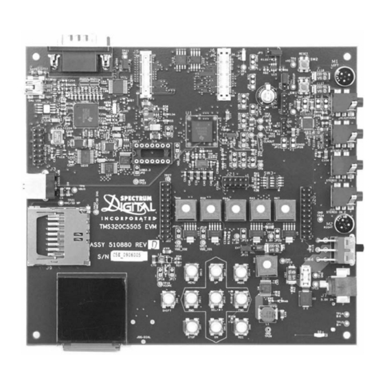
The VC5505 EVM is a 6.35 x 5.75 inch (161 x 146 mm.) ten (10) layer board which is powered by an external +5 volt only power supply. Figure 2-1 shows the layout of the top side of the VC5505 EVM. DS201 J201 SW14 SW15 SW11 SW13 SW10 SW12 Figure 2-1, TMS320VC5505 EVM (top) - Page 18 Spectrum Digital, Inc Figure 2-2 shows the layout of the bottom side of the VC5505 EVM. Figure 2-2, TMS320VC5505 EVM (bottom) TMS320VC5505 EVM Technical Reference...
-
Page 19: Connector Index
Spectrum Digital, Inc 2.2 Connector Index The TMS320VC5505 EVM has twenty-two (22) connectors which provide the user access to the various signals on the EVM. Table 1: TMS320VC5505 EVM Connectors Schematic Connector # Pins Function Board Side Page I2C Probe Headers... - Page 20 The J3 connector is a USB Type B connector. This connector interfaces directly to the VC5505 processor. The signals on this connector are shown in the table below. Table 3: J3, USB Type B Connector VC5505 Signal, Pin # USB Signal VBUS USB VBUS, J12 USB_DM, J14 USB_DP, H14 TMS320VC5505 EVM Technical Reference...
- Page 21 Spectrum Digital, Inc 2.2.3 J4, External JTAG Header The TMS320VC5505 EVM is supplied with a 14 pin header interface, J4. This is the standard interface used by JTAG emulators to interface to Texas Instruments processors. The pinout for the connector is shown in the figure below.
- Page 22 I2S2_FS / LCD_DATA9 / SPI_CS0 I2S2_RX / LCD_DATA10 / SPI_RX I2S2_DX / LCD_DATA11 / SPI_DX LCD_RE / SPI_ALT_CLK LCD_DATA0 / SPI_ALT_RX SDCLK LCD_DATA1 / SPI_ALT_DX SDCLKE LCD_BIAS_OE / SPI_CS0 LCD_MCLK / SPI_ALT_CS1 LCD_nWE / SPI_ALT_CS2 LCD_ALE / SPI_ALT_CS3 TMS320VC5505 EVM Technical Reference...
- Page 23 Spectrum Digital, Inc 2.2.5 J6, Expansion Connector Expansion connector J6 is a female receptacle used for attaching daughter cards to the EVM. The pin out for this connector is shown in the figure below. Table 5: J6, Expansion Connector Pin #...
- Page 24 Spectrum Digital, Inc 2.2.6 J7, +5 Volt In Connector Power (+5 volts) is brought onto the TMS320VC5505 EVM via the J7 connector. The connector has an outside diameter of 5.5 mm. and an inside diameter of 2.5 mm. The diagram of J7 is shown below.
- Page 25 Spectrum Digital, Inc 2.2.8 J9, MMC/SD Connector Connector J9 is used to provide a MMC/SD interface to the VC5505 processor. The signals on this connector are shown in the table below. Table 6: J9, MMC/SD Connector Pin # Signal Name MMC0.DATA3...
- Page 26 These inputs connect to AIC LINE2L and AIC LINE2R of the TLV320AIC3254. The signals on the mating plug are shown in the figure below. Ground Right Line In Left Line In Figure 2-7, Stereo In 1 Jack 2-12 TMS320VC5505 EVM Technical Reference...
- Page 27 Spectrum Digital, Inc 2.2.11 J15, Stereo In 2 Connector The J15 connector in is a stereo input. The input connector is a 3.5 mm stereo jack. These inputs connect to AIC LINE3L and AIC LINE3R of the TLV320AIC3254. The signals on the mating plug are shown in the figure below.
- Page 28 AIC3254 ROUT of the TLV320AIC3254.The output connector is a 3.5 mm stereo jack. The signals on the mating plug are shown in the figure below. Ground Right Line Out Left Line Out Figure 2-11, Stereo Out Connector 2-14 TMS320VC5505 EVM Technical Reference...
- Page 29 Spectrum Digital, Inc 2.2.15 J19, Display Interface Connector J19 provides an interface to a display module. This connector is located on the bottom side of the board. The signals on this connector are shown in the table below. Table 9: J19, Display Interface...
- Page 30 Spectrum Digital, Inc 2.2.16 Daughter Card Interfaces The TMS320VC5505 EVM has 3 daughter card interfaces. The Medical Development Kit (MDK) daughter cards from Texas Instruments use these interfaces. For more information about these cards refer to the following web sites: http://focus.ti.com/docs/toolsw/folders/print/tmdxmdkek1258.html...
- Page 31 Spectrum Digital, Inc 2.2.16.3 J22, Daughter Card Interface Connector J22 is a 2 x 11 double row male header (.1 in. centers) used to interface to plug on daughter cards. The signals on this connector are shown in the table below.
-
Page 32: System Leds
Schematic Color Function Designator Page Green Connected to the XF bit on the VC5505 processor Indicates +5 volts is applied at the J7 connector DS201 Green USB activity, blinks during USB access to embedded emulation 2-18 TMS320VC5505 EVM Technical Reference... - Page 33 The VC5505 EVM has 5 potentiometers that allow the user to evaluate the low power features of the processor. These adjustable resistors and the voltage they control are shown in the table below. Table 15: TMS320VC5505 EVM Potentiometers Schematic Board...
- Page 34 2.5.4 SW4, On/Off Switch The On/Off switch provides +5 volts to the logic on the board. In the “OFF” position this switch interrupts the power from the power supply as well as the battery holder. 2-20 TMS320VC5505 EVM Technical Reference...
- Page 35 Spectrum Digital, Inc 2.5.5 SW6 - SW15, Function Switches Switches SW6-SW15 are push button momentary switches which are read by the processor. These switches can take on any function defined by user software. The silk screen nomenclature is provided for user convenience and are shown in the table below.
- Page 36 EVM board are shown in the figure below. JP22 JP13 JP12 JP14 JP10 JP25 JP29 JP27 JP26 JP24 JP23 JP28 JP11 JP20 JP19 JP15 JP16 JP17 JP21 JP18 Figure 2-12, TMS320VC5505 EVM Jumpers 2-22 TMS320VC5505 EVM Technical Reference...
- Page 37 Spectrum Digital, Inc 2.6.1 VC5505 EVM Option Jumpers The fourteen (14) option jumpers fall into two categories; factory installed(9), and user selectable(5). The factory installed jumpers are pre-configured with a zero ohm resistor at the factory and are not meant to be changed by users. The table below lists the factory installed option jumpers and their function.
- Page 38 V3.3 is sourced from the +5 volt power supply Shown below is a top view of the JP15. 3.3V SEL 3.3V SEL Factory JP15 JP15 Configuration 1-2 Position 2-3 Position Figure 2-21, Top View of the Jumper JP15 2-24 TMS320VC5505 EVM Technical Reference...
- Page 39 Spectrum Digital, Inc 2.6.1.3 JP17, Vsel Select Jumper JP17 is a two position unpopulated jumper that routes V3.3 to the VSEL of the of the TPS6254. This jumper is pre-configured at the factory to be shorted (*). The table below shows the positions and their function.
- Page 40 GND pulldown is the signal level sourced to the WAKEUP signal of the VC5505 processor Shown below is a top view of the JP25. Factory Configuration 1-2 Position 2-3 Position Figure 2-25, Top View of the Jumper JP25 2-26 TMS320VC5505 EVM Technical Reference...
- Page 41 Spectrum Digital, Inc 2.6.2 VC5505 EVM Power Domain Probe Points The VC5505 EVM has pre-designed probe points in the circuitry which could be used to observe power domains. These measurement points consist of a 2 pin 0.1 inch spaced printed circuit board (pcb) footprint jumper shorted by a zero ohm resistor. The probe points are shown in the table below.
-
Page 42: Test Points
VC5505 EVM are shown in the figure below. TP11 TP25 TP27 TP23 TP24 TP22 TP19 TP21 TP10 TP12 TP13 TP14 TP15 TP16 TP20 TP17 TP18 TP26 Figure 2-27, TMS320VC5505 EVM Test Points 2-28 TMS320VC5505 EVM Technical Reference... - Page 43 Spectrum Digital, Inc The table below shows the signals present on each test point. Table 28: VC5505 EVM Test Points Test Schematic Signal Point # Page WAKEUP INT0 INT1 nRESET VBUS CLKOUT RTC_CLKOUT TP10 TP11 TP12 TP13 +5 Volt In...
- Page 44 Spectrum Digital, Inc 2-30 TMS320VC5505 EVM Technical Reference...
- Page 45 Appendix A Schematics This appendix contains the schematics for the TMS320VC5505 EVM. Board components with designators over 200 (e.g. DS210, R211) are part of Spectrum Digital’s embedded JTAG emulator and are not included in these schematics.
- Page 46 Spectrum Digital, Inc TMS320VC5505 EVM Technical Reference...
- Page 47 Spectrum Digital, Inc...
- Page 48 Spectrum Digital, Inc TMS320VC5505 EVM Technical Reference...
- Page 49 Spectrum Digital, Inc...
- Page 50 Spectrum Digital, Inc TMS320VC5505 EVM Technical Reference...
- Page 51 Spectrum Digital, Inc...
- Page 52 Spectrum Digital, Inc TMS320VC5505 EVM Technical Reference...
- Page 53 Spectrum Digital, Inc...
- Page 54 Spectrum Digital, Inc A-10 TMS320VC5505 EVM Technical Reference...
- Page 55 Spectrum Digital, Inc A-11...
- Page 56 Spectrum Digital, Inc A-12 TMS320VC5505 EVM Technical Reference...
- Page 57 Spectrum Digital, Inc A-13...
- Page 58 Spectrum Digital, Inc A-14 TMS320VC5505 EVM Technical Reference...
- Page 59 Spectrum Digital, Inc A-15...
- Page 60 Spectrum Digital, Inc A-16 TMS320VC5505 EVM Technical Reference...
- Page 61 Spectrum Digital, Inc A-17...
- Page 62 Spectrum Digital, Inc A-18 TMS320VC5505 EVM Technical Reference...
-
Page 63: Mechanical Information
Appendix B Mechanical Information This appendix contains the mechanical information about the TMS320VC5505 EVM produced by Spectrum Digital. - Page 64 Spectrum Digital, Inc TMS320VC5505 EVM Technical Reference...
- Page 65 Spectrum Digital, Inc...
- Page 66 Spectrum Digital, Inc TMS320VC5505 EVM Technical Reference...
- Page 68 Printed in U.S.A., July 2009 510885-0001 Rev. B...
Need help?
Do you have a question about the TMS320VC5505 and is the answer not in the manual?
Questions and answers