Advertisement
Quick Links
Using the CY3274-HV High Voltage 110-240 V AC PLC Development Kit
To evaluate this kit, a second CY3274 kit is needed. This guide assumes that two CY3274 kits are available.
1
1. Install CY3274 Kit installer from the kit website. Open PSoC
Programmer from Start menu.
2. Set AutoDetection to Off, set the 'Device Family' to
CY8C-PLC-LED16P, 'Device' to CY8CPLC20-OCD, programming
mode to Reset and Verification to either option.
3. Open the CY3274_PLC_Demo.hex file from the firmware ->
CY3274_PLC_Demo inside CY3274 kit installation folder.
3
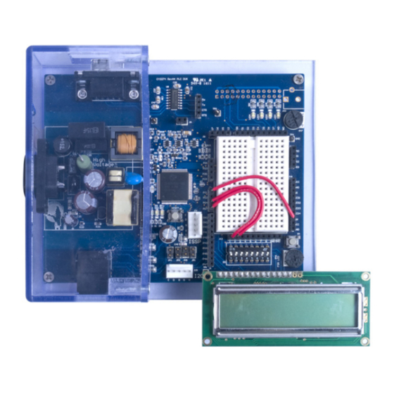
1. Connect the LCD Module to LCD1 header.
2. On kit 1, connect a jumper wire from SW (on J18) to P0[1] (on
J13), from P0[4] to one of the 8 DIP switches on J12 (the 8 DIP
switch array on S3 is connected to J12) and from P0[7] to another
DIP switch.
3. Repeat steps 1 and 2 on kit 2 as well.
4. Put the 2 DIP switches (S3) on kit 1 to ON position to set it as Tx
and the 2 DIP switches on kit 2 to OFF position to set it as Rx.
5
CY3274-HV PLC DEVELOPMENT KIT
QUICK START GUIDE
CAUTION: High Voltage (Risk of Electric Shock)
All work in powerline communications must be done with extreme care.
Caution must be exercised when using power supplies or power related equipment.
2
1. Connect the USB cable from the PC to the MiniProg programmer.
Connect the MiniProg to the ISSP header J21 on kit 1.
2. In PSoC Programmer, power the device by clicking 'Toggle Power'
button. Click the Program button (downward arrow). When the
status says 'Programming Successful', remove the MiniProg from
the ISSP header.
3. Repeat the above programming operation on kit 2.
4
1. Connect the power cable from the AC mains to the AC power
connector on the first CY3274 kit. The blue LED (DS1) turns on.
Repeat the same for kit 2.
1. Push the reset button S2 on both nodes. A message "PLC Demo"
initially appears on the LCD. The kit will be a transmitter if the DIP
switch connected to P0[7] is pulled high, else the kit will act as a
receiver.
2. Press the push button (S4) on transmitter to start transmission of
packets upto a packet count of 1000. The LCD shows transmission
statistics.
3. Transmission can be started or halted (if transmission is in progress)
or resumed (if transmission is halted) or restarted (when the packet
count of 1000 is completed) by pressing the push button (S4) on
the transmitter kit.
4. Received packet count can be reset by pressing the push button
(S4) on the receiver kit.
Advertisement

Related Manuals for Cypress CY3274-HV


Summary of Contents for Cypress CY3274-HV
- Page 1 CY3274-HV PLC DEVELOPMENT KIT QUICK START GUIDE Using the CY3274-HV High Voltage 110-240 V AC PLC Development Kit CAUTION: High Voltage (Risk of Electric Shock) All work in powerline communications must be done with extreme care. Caution must be exercised when using power supplies or power related equipment.
- Page 2 (JP1, JP3, JP4, JP5) LEDs (DS2, DS3, DS4) For the latest information about this kit visit www.cypress.com/go/plc © 2009-2014 Cypress Semiconductor Corporation. All rights reserved. All trademarks or registered trademarks referenced herein are the properties of their respective owners. DOC#: 001-54836 REV *E...
Need help?
Do you have a question about the CY3274-HV and is the answer not in the manual?
Questions and answers