
Related Manuals for TOPP S200


Summary of Contents for TOPP S200
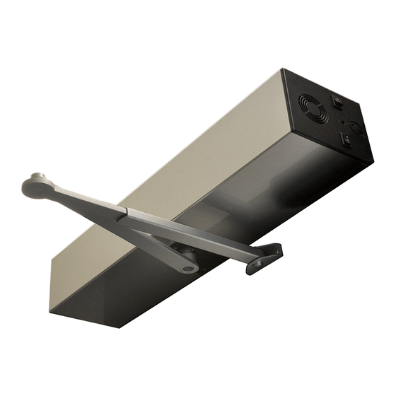
- Page 1 S200 INSTRUCTIONS FOR INSTALLATION AND USE STANDARD INSTALLATION ORIGINAL INSTRUCTION COD. 0P5701 VER. 00 REV.03.20 instructions for installation...
- Page 2 S200 INDEX TECHNICAL DATA GENERAL INFORMATION and PAG 3 SAFETY PAG 4 PRELIMINARY OPERATIONS PAG 5 ARTICULATED ARM INSTALLATION PAG 6 SLIDING ARM INSTALLATION SLIDING ELBOW ARM INSTALLATION PAG 8 PAG 10 ELECTRICAL CONNECTIONS FIRST STARTUP PAG 12 SELF LEARNING PAG 17...
-
Page 3: Technical Data
S200 -AUTOMATION FOR SWING DOORS The Automation S200 for hinged doors is designed and produced in accordance to the European standard EN16005. It is designed to for indoor installation only. The automation is an electromechanical type servo-assisted by a spring that ensures the closure in case of lack of electric and battery power. -
Page 4: General Information And Safety
• Automation S200 in low energy operating mode can be installed in places where the door is used by disabled, elderly or fragile persons or persons with limited motor capacity, after performing the risk analysis and considering that the risk for this type of user is low. -
Page 5: Preliminary Operations
S200 PRELIMINARY OPERATIONS ELECTRONIC BOARD DIP-SWITCHES SETTING open full energy pushing mode- open low energy pulling mode- ONLY IN CASE OF LOW ENERGY INSTALLATION WITH ARTICULATED ARM AND DOOR WIDTH BELOW 800mm: 1) DISCONNECT THE FULL ENERGY PLUG DISCONNECT 2) TURN THE AUTOMATION 180° AND CONNECT THE LOW ENERGY PLUG... - Page 6 S200 ARTICULATED PUSHING ARM INSTALLATION COMPONENTS 1- Cover, triangular plates and 6 fixing screws 2- Automation S200 3- Fixing plate 4- Automation fitting nuts 5- Articulated arm * 6- Axle extension and corresponding screw (optional) * * Supplied separately Automation positioning with left hinge...
- Page 7 S200 ARTICULATED PUSHING ARM INSTALLATION AUTOMATION INSTALLATION S200 with articulated pushing arm DRILLING HOLES Check the correct direction of the arrow on the fixing plate With a suitable drill, make the 6 holes as per the position specifications and insert the 6 anchors in...
- Page 8 S200 SLIDING PULLING ARM INSTALLATION COMPONENTS 1- Cover, triangular plates and 6 fixing screws 2- Automation S200 3- Fixing plate 4- Automation fitting nuts 5- Sliding arm * 6- Axle extension and corresponding screw (optional) * * Supplied separately Automation positioning with left hinge...
- Page 9 S200 SLIDING PULLING ARM INSTALLATION AUTOMATION INSTALLATION S200 with pulling sliding DRILLING HOLES Check the correct direction of the arrow on the fixing plate With a suitable drill, make the 6 holes as per the position specifications and insert the 6 anchors in the...
- Page 10 S200 SLIDING PULLING ARM INSTALLATION - ELBOW COMPONENTS 1- Cover, triangular plates and 6 fixing screws 2- Automation S200 3- Fixing plate 4- Automation fitting nuts 5- Sliding elbow arm * 6- Axle extension and corresponding screw (optional) * * Supplied separately...
- Page 11 S200 SLIDING PULLING ARM INSTALLATION - ELBOW AUTOMATION INSTALLATION S200 with pulling sliding elbow arm DRILLING HOLES Check the correct direction of the arrow on the fixing plate With a suitable drill, make the 6 holes as per the position specifications and insert the 6 anchors in the...
-
Page 12: Electrical Connections
S200 ELECTRICAL CONNECTIONS BEFORE MAKING THE ELECTRICAL CONNECTION OF THE AUTOMATION, CHECK THAT: • The main power supply connected to the automation must comply with the requisites contemplated by the legislation in force in the country of installation, and must have the technical characteristics indicated in tab.2- cap.2.5 and on the rating plate, as well as the “CE”... - Page 13 S200 ELECTRICAL CONNECTIONS PRE-WIRED ELECTRIC CONNECTIONS - ELECTRONIC BOARD * not regulated instructions for installation...
- Page 14 S200 ELECTRICAL CONNECTIONS SAFETY SENSORS CONNECTION, IF THEY ARE PRESENT CONNECTION OF IS6 TOPP SAFETY SENSOR HOTRON SSS-5 CONNECTION OF OPTEX SAFETY SENSORS OPTEX AO EDGE T instructions for installation...
- Page 15 S200 ELECTRICAL CONNECTIONS SUPPLEMENTARY SAFETY SENSORS CONNECTION, IF THEY ARE PRESENT CONNECTION OF IS6 TOPP SUPPLEMENTARY SAFETY SENSOR- HOTRON SSS-5 CONNECTION OF OPTEX SUPPLEMENTARY SAFETY SENSORS OPTEX AO EDGE T instructions for installation...
- Page 16 S200 ELECTRICAL CONNECTIONS ACTIVATION SENSORS CONNECTION, IF THEY ARE PRESENT ATTIVAZIONE 1 1 7 7 1 1 8 8 N.O. 1 1 9 9 1 1 2 2 2 2 0 0 1 1 3 3 2 2 1 1...
- Page 17 1.Press and hold the <DOWN> key for 5 seconds, the display shows the word “RADIO” blinking on the 7-segment display. 2.If you are using the 4-channel Topp TS1S remote control, press the second button (closed function). To confirm that the remote control has been memorized, the blinking word “RADIO”...
- Page 18 S200 DOUBLE LEAF INSTALLATION DOUBLE LEAF OPERATION Perform the mechanical installation and the electric wiring assuming the two leaves would be independent, following page 6 in presence of articulated arm or page 8 sliding arm or page10 elbow arm. The Double leaf operation has a MASTER and a SLAVE leaf. The MASTER leaf is the first one to OPEN.
-
Page 19: Maintenance
A regular maintenance is required to ensure the correct operation of the automation, this maintenance activity may be carried out either by TOPP, in accordance with a specific agreement made with the user, or by the installation technician or by other competent and qual-ified technical personnel in possession of all legal requirements. - Page 20 S200 LIST OF ERROR MESSAGES AND NOTICES instructions for installation...
- Page 21 S200 CONFIGURATION OF AUTOMATION PARAMETERS CONFIGURATION OF PARAMETERS/FUNCTIONS It is possible to enter the basic parameters using the 7 segment display and the <ENTER> and <DOWN> keys.Press and hold <ENTER> for 5 sec to enter the configuration menu. Press <DOWN> to pass from a parameter to another, press <ENTER>...
- Page 22 S200 CONFIGURATION OF AUTOMATION PARAMETERS val. ref. display parameter description value description *default* SAFETY LOGIC NO with active low test (to GND) Setting with logic of the 4 safety sensors. For values NC with active high test (NC with test 24V)
- Page 23 S200 CONFIGURATION OF AUTOMATION PARAMETERS val. ref. display parameter description value description *default* Resets everything MAINTENANCE Resets only cycle counter Reset only distance 0° ANGLE OF INHIBITION OF 3° OBSTACLE SAFETY SENSOR 6° 9° Blind spot of safety sensor on opening (hinge side): 12°...
- Page 24 S200 CONFIGURATION OF AUTOMATION PARAMETERS val. ref. display parameter description value description *default* 10 s 15 s DOOR OPEN PAUSE TIME. 20 s Regulates the open door pause time after radar 30 s reading. 40 s 60 s 120 s...
- Page 25 S200 CONFIGURATION OF AUTOMATION PARAMETERS val. ref. display parameter description value description *default* FINAL STROKE Increasing the value increases the force. Serves to regulate the closing velocity and facilitate the fastening of the electric lock. ELECTRIC LOCK STATUS CON- TROL MODE...
- Page 26 S200 PRE-WIRED ELECTRIC CONNECTIONS instructions for installation...
- Page 27 S200 AUTOMATIC SPRING LOAD 1Automatic load procedure: The display shows Simultaneously press ENTER BUTTON - DOWN BUTTON and “TURN ON” the automation. The display shows «REC» TURN ON Hold down 2-Press and hold down Load DOWN BUTTON until the reference F is aligned with...
-
Page 28: Arm Removal
S200 LATERAL COVERS – DISASSEMBLY AND REASSEMBLY ARM REMOVAL 1) Make sure that the spring is locked by inserting both the grub screws (GLM and GLS). 2) Isert the extractor cap by screwing it clockwise. 3)Turn the fastening screw anti-... - Page 29 S200 DISABLE SPECIAL FUNCTIONS SERVOASSISTED FUNCTION WITH DISABLE USER BUTTON By connecting the external and internal opening buttons as per the following diagram and correctly setting parameter 113 on the board, the door will enter Servo / Push & GO mode. Setting parameter 113 = 3, the Push & GO function is activated with safety sensors activated Setting parameter 113 = 2 the Push &...
-
Page 30: Ec Declaration Of Conformity
S200 EC DECLARATION OF CONFORMITY instructions for installation... - Page 31 S200 instructions for installation...
-
Page 32: Instruction For Installation
S200 INSTRUCTION for INSTALLATION Max capacity 250 Kg Società a socio unico soggetta a direzione e coordinamento di 2 Plus 3 Holding S.p.a. via Galvani 59, 36066 Sandrigo (VI) tel. +39 0444 656700 fax +39 0444 656701 www.topp.it info@topp.it instructions for installation...
Need help?
Do you have a question about the S200 and is the answer not in the manual?
Questions and answers