Table of Contents
Advertisement
Advertisement
Table of Contents

Subscribe to Our Youtube Channel
Related Manuals for Millipore Milli-Q Integral 3


Summary of Contents for Millipore Milli-Q Integral 3
- Page 1 ® User Manual Milli-Q Integral 3/5/10/15 Systems...
- Page 2 Water Purification System. • If this User Manual is not the correct one for your Water Purification ® System, then please contact Millipore The term “Milli-Q Integral Water Purification System” is replaced by the Terminology term “Milli-Q System” for the remainder of this User Manual unless otherwise noted.
- Page 3 Millipore Corporation assumes no responsibility for any errors that might appear in this document. This manual is believed to be complete and accurate at the time of publication. In no event shall Millipore Corporation be liable for incidental or consequential damages in connection with or arising from the use of this manual.
- Page 4 A10, Elix, Q-POD, Quantum, Milli-Q, Millipak and Progard are registered trademarks of Millipore Corporation. Millipore is a registered trademark of Millipore Corporation. The M mark is a trademark of Millipore Corporation. E-POD, BioPak, EDS-Pak and ROClean are trademarks of Millipore Corporation.
- Page 5 Do not remove the covers of the Milli-Q System at any time. Electrical and mechanical components inside the Milli-Q System could pose a hazard. A qualified Millipore Service Representative should perform any work that needs to be done while the Milli-Q System is opened.
-
Page 6: Table Of Contents
Dispensing water ........................83 Printing ..........................86 Lab Closed feature ......................91 Viewing water quality ......................93 Viewing Operation ......................95 Viewing Consumable Status ....................98 Calling Millipore ......................100 Viewing Information ......................101 Maintenance ...........................103 Overview ..........................103 Maintenance Schedule......................104 Replacing the Progard Pack and Vent Filter ..............106 Replacing the Quantum Cartridge..................110... - Page 7 Sanitising or cleaning the RO Cartridge(s) ..............119 Cleaning the Inlet Strainer....................124 Alarms.............................127 Overview ..........................127 Alarm Information......................128 Summary of Alarm messages...................133 Alerts............................139 Overview ..........................139 Alert information......................140 Summary of Alert messages.....................147 Ordering Information ......................152 Consumables, Accessories and Systems ................152...
-
Page 8: Product Information
Product Information Overview Purpose This chapter contains topics related to the Milli-Q System. Some of the more important topics in this chapter are: • installation requirements, • consumable information, and • dimensions of various components of the Milli-Q System Contents This chapter contains the following topics: Topic See Page... -
Page 9: Cabinet
Cabinet Overview Item Description/Name Main Display Connections for tubings, power cord, level sensor and other cables ® Progard Pack ® Quantum Cartridge Sanitisation Port Main Display The Main Display is used to navigate the Milli-Q System software. function Continued on next page... - Page 10 Cabinet, Continued Details of the Main Display Item Description LEDs • Green = No Alerts or Alarms • Yellow = Alert • Red = Alarm Main LCD Main Keypad • The use of the Right Keypad button is shown below. •...
- Page 11 Cabinet, Continued The use of the Left Keypad button is shown below. Left Diagram 1 Action Diagram 2 Press The use of the Up Keypad button is shown below. Diagram 1 Action Diagram 2 Press The use of the Down Keypad button is shown below. Down Diagram 1 Action...
- Page 12 Cabinet, Continued The use of the Validate Keypad button is shown below. Diagram 1 Action Diagram 2 Validate Press • The READY Mode screen display is explained below. READY Mode • This screen display shows the resistivity and temperature of the water filling –...
- Page 13 Cabinet, Continued LEDs The LEDs are described below. Item Description Green LED Milli-Q System is operating within specifications. Yellow LED An Alert is present. Red LED An Alarm is present. NOTE: • If an Alarm and an Alert are present at the same time, then only the red LED is lit.
- Page 14 Cabinet, Continued Ports and cables Item Description Item Description RO Reject Port E-POD™ Unit (Accessory) Port Feedwater Port Reservoir Port Port for RC-Link to Q-POD Power Entry connection Unit (100 – 240 V) Port for RC-Link to Q-POD Accessories connection Unit (maximum 24 VDC) E-POD Unit (Accessory)
-
Page 15: Q-Pod Unit
Q-POD Unit Overview Item Description ® Q-POD Plunger Point of Delivery POD Pak (BioPak™ Ultrafilter pictured here) Q-POD Arm Q-POD Mast Q-POD Base Q-POD Display Q-POD Keypad Continued on next page... - Page 16 Q-POD Unit, Continued Display The Q-POD Display is shown and explained here. • STANDBY Mode is used only to access the Maintenance and Manager Display - 1 STANDBY and Menus. READY • READY Mode is the normal mode for Milli-Q Water production and delivery.
- Page 17 Q-POD Unit, Continued Display – 4 Status of consumables Progard Pack out Progard Pack in use Progard Pack not in use UV 185 nm Lamp on UV 254 nm Lamp on UV Lamps off Quantum Cartridge out Quantum Cartridge in Quantum Cartridge not in use NOTE:...
- Page 18 Q-POD Unit, Continued Display – • The Milli-Q System has dispensed FLOW AUTOSTOP beyond the POD FLOW STOP Alarm time. The FLOW AUTO STOP Steady Alarm is shown on the Main Display. • Press the Q-POD Plunger all the way down and release. Display –...
- Page 19 Q-POD Unit, Continued Keypad The Q-POD Keypad is shown and explained here. Item Description Press to start Milli-Q Water Recirculation Decrease volume Press to start volumetric dispensing Increase volume Press to get Instant Quality printout (if a printer is connected to the Q-POD Unit) Connections Item Description...
- Page 20 Q-POD Unit, Continued Termination The Termination Plug (shown below) is connected next to the PS/2 cable on Plug the Q-POD Base. • The RC-Link is the set of tubings and the PS/2 cable inside a sheath. RC-Link • The RC-Link is 2.7 metres in length. Item Description PS/2 Cable...
-
Page 21: Reservoir
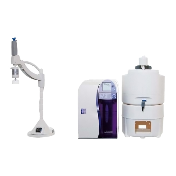
Reservoir Information Millipore recommends using a Reservoir having the following catalogue number: Size Catalogue Number 30 Litre TANKPE030 60 Litre TANKPE060 100 Litre TANKPE100 • An example of a Milli-Q System is shown here. Example • This pictures shows an (from left to right): −... -
Page 22: Consumables
Consumables Flow diagram The water flow through a Milli-Q System is shown here in a flow diagram. The various consumables are described below. Item Description Item Description Progard Pack Quantum Cartridge ® UV 254 nm Lamp TOC Monitor Lamp UV 185 nm Lamp POD Pak Continued on next page... - Page 23 Consumables, Continued • The Progard Pack protects the RO Cartridge in order to increase its lifetime. Progard Pack • The Progard Pack prevents mineral scaling, organic fouling and chlorine oxidation of the RO Cartridge(s). Item Description Progard Pack Performs benefits listed above. •...
- Page 24 Consumables, Continued • The A10 TOC Monitor uses a small lamp during its TOC Analysis Mode. A10 Lamp • This is called the A10 Lamp. • The POD Pak is the final water purification device. POD Pak • It is attached to the Point of Delivery outlet. •...
-
Page 25: Specifications And Requirements
Operating Dry Weight Shipping Weight Weight Q-POD Unit 4.7 kg 4.6 kg 7.2 kg Milli-Q Integral 3 Cabinet 24 kg 18 kg 22 kg Milli-Q Integral 5 Cabinet 25 kg 19 kg 23 kg Milli-Q Integral 10 Cabinet 27 kg... - Page 26 Frequency • 3.15 Amp Fast Acting; 5 mm x 20 mm; 250 V Main Fuse safety voltage. • The fuse should be serviced by a qualified Millipore Service Representative. Power Used 160 VA Power Cord Length 2.5 metres Electrical Ground Earth Grounded •...
- Page 27 Specifications and requirements, Continued Dimensions 50 cm 48.4 cm 33.2 cm 34.6 cm 54.6 52.2 81.4 57.9 45.7 55 cm ∅ 23 cm Continued on next page...
- Page 28 Specifications and requirements, Continued Materials of Please contact Millipore for a list of the Materials of Construction. construction Feedwater The Feedwater requirements are listed here. Parameter Value Type of Feedwater Potable tap water < 2000 μS/cm Conductivity Pressure 1 bar < P < 6 bar Temperature 5°C <...
- Page 29 Specifications and requirements, Continued • The minimum consumables required for installation are listed here. Consumables • Note that these items are not shipped with the Milli-Q System and must be ordered separately: − Progard Pack, − Quantum Cartridge, and − POD Pak. Reservoir The Reservoir must be located relative to the Milli-Q Cabinet: •...
-
Page 30: Installation
Installation Overview Purpose This chapter explains how to install the Milli-Q System. Contents This chapter contains the following topics: Topic See Page Alarms generated during installation Q-POD Unit Main Cabinet tubings, cables and power cord Installing the Quantum Cartridge Installing the Progard Pack Rinsing the RO Cartridges Rinsing the Quantum Cartridge Installing a POD Pak... -
Page 31: Alarms Generated During Installation
Alarms generated during installation • During the installation of a Milli-Q System, certain Alarm messages are Overview generated. • This occurs because: − the Reservoir is empty, − there is air in the tubings and in the Progard Pack, − the Progard Pack is not installed, −... - Page 32 Alarms generated during installation, Continued • This alarm occurs because the Quantum Cartridge is not fully rinsed out or MILLI-Q RES < SP, there is air in the tubing near a resistivity sensor. REPLACE • This alarm goes away when a few litres of water are dispensed from the QUANTUM Q-POD Unit.
- Page 33 Alarms generated during installation, Continued Eliminate LOW FEED WATER Step Action Diagram PRESSURE message Press (continued) • The Milli-Q System tests the feedwater pressure again. • If the pressure is sufficient, then the alarm does not appear again.
-
Page 34: Q-Pod Unit
Q-POD Unit Assembling Follow the steps below to assemble the Q-POD Unit. Step Action Result • Open the Q-POD Unit box. • Locate the Q-POD Base and the Q-POD Mast. • Screw them together. • Locate the Q-POD Arm. • Press on the locking handle and slide the Q-POD Arm onto the Q-POD Mast. - Page 35 Q-POD Unit, Continued Connecting the Follow the steps below to connect the RC-Link to the Q-POD Base. RC-Link Step Action Diagram Locate the two tubing ports on the back of the Q-POD Base. Connect the RC-Link tubing to the Q-POD Ports: •...
- Page 36 Q-POD Unit, Continued Connecting the RC-Link Step Action Diagram (continued) Connect the Termination Plug to the other PS/2 port on the Q-POD Base. Make sure the PS/2 cable and the Termination Plug are well connected to the Q-POD Unit.
-
Page 37: Main Cabinet Tubings, Cables And Power Cord
Main Cabinet tubings, cables and power cord Summary Item Description RO Reject Water tubing goes to a drain. Feedwater supply tubing to Milli-Q Integral system. Tubing to Q-POD Unit. Use the RC-Link tubing. Tubing to Q-POD Unit. Use the RC-Link tubing. Water to E-POD Unit (accessory). - Page 38 Main Cabinet tubings, cables and power cord, Continued Reservoir The tubings from Milli-Q Cabinet Ports 7 and 9 are connected to the connections Reservoir as shown here. NOTE: The valve where the tubing from Port 7 is connected must be opened. •...
- Page 39 Main Cabinet tubings, cables and power cord, Continued • Plug the power cord into the Milli-Q System. Powering the • Plug the power cord into a source of electrical power. system • The Main LCD shows a series of start-up screens. •...
-
Page 40: Installing The Quantum Cartridge
Installing the Quantum Cartridge Procedure Follow the steps below to install a new Quantum Cartridge. Step Action Diagram • Open the right door of the Milli-Q System Cabinet. • Remove the 2 protective caps located on the ports inside. • Remove the covers on the 2 ports of the Quantum Cartridge. - Page 41 Installing the Quantum Cartridge, Continued Procedure (continued) Step Action Diagram Press...
-
Page 42: Installing The Progard Pack
Installing the Progard Pack • Follow the steps below to install a new Progard Pack. Procedure • After the Progard Pack is installed, the Milli-Q System starts an automatic flush. • During Milli-Q System installation procedure, the automatic flush is cancelled. - Page 43 Installing the Progard Pack, Continued Procedure (continued) Step Action Diagram • Remove the covers on the 2 ports of the Progard Pack. • Make sure the rubber O-rings are firmly in place. • Wet the O-rings with water. Push the top of the Progard Pack into the ports on the Milli-Q System.
- Page 44 Installing the Progard Pack, Continued Procedure (continued) Step Action Diagram • Push the pack locking handle down. • Close the left door. One minute later, the Main LCD shows that a new Progard Pack is installed. Press • Wait 5 minutes. •...
-
Page 45: Rinsing The Ro Cartridges
Rinsing the RO Cartridges • The RO Cartridges must be flushed and rinsed when the Milli-Q System is installed. Very • Failure to do this results in poor water quality. important! Rinse the RO Cartridges Procedure Follow the steps below to flush and rinse the RO Cartridge(s). Step Action Diagram... - Page 46 Rinsing the RO Cartridges, Continued Procedure (continued) Step Action Diagram • Select <Install new RO>. • Press Press Press Press After 15 minutes, the LCD looks like this. Continued on next page...
- Page 47 Rinsing the RO Cartridges, Continued Procedure (continued) Step Action Diagram When the 225 minute RO rinse is finished, the Milli-Q System returns to READY Mode. • The Reservoir is now being filled. • The Reservoir water level is indicated on the bottom of the READY Mode screen or on the Q-POD Display.
-
Page 48: Rinsing The Quantum Cartridge
Have enough • If there is not enough water in the Reservoir, the TANK EMPTY Alarm is water! shown. Additionally, air can enter the tubings and can temporarily affect other sensors. Millipore Reservoir Minimum 30 Litre 100% Tank Level 60 Litre >... - Page 49 Rinsing the Quantum Cartridge, Continued Procedure Follow the steps below to rinse the Quantum Cartridge. Step Action Diagram • Locate the clear tubing and the barbed fitting from the Milli-Q System Accessories Bag. • Screw the barbed fitting onto the Q-POD Unit. •...
- Page 50 Rinsing the Quantum Cartridge, Continued Procedure (continued) Step Action Diagram Dispense water for about 10 minutes. • Push the Q-POD Plunger all the way down and then release it to stop dispensing water. • Leave the Milli-Q System in READY Mode.
-
Page 51: Installing A Pod Pak
Installing a POD Pak Overview The installation of a POD Pak involves 2 steps. These are: • placing and flushing the POD Pak onto the Q-POD Unit, and • registering the installation of a specific POD Pak. Placing and Follow the instructions delivered with the POD Pak. flushing Registering Follow the steps below to register the installation of the POD Pak. - Page 52 Installing a POD Pak, Continued Registering (continued) Step Action Diagram • Scroll down to <Install Q-POD Pak 1>. • Select it. Press Press • In this example, you choose <Millipak>. • Press Press Continued on next page...
- Page 53 Installing a POD Pak, Continued Registering (continued) Step Action Diagram Press Press 3 times on...
-
Page 54: Registering Uv Lamp Timers
Registering UV Lamp timers • The timer used for each UV Lamp must be reset when the Milli-Q System is Introduction installed. • If this is not done, then the message indicating that a Lamp replacement is needed is shown too early. •... - Page 55 Registering UV Lamp timers, Continued Procedure (continued) Step Action Diagram • Select <Install UV 254 nm Lamp>. • Press Press Press Press Press 3 times on Reset timer for After resetting the UV 254 nm Lamp timer, reset the UV Lamp timer for the: •...
-
Page 56: Registering
Registering <Examine Inlet Strainer> message timer • The timer used for cleaning the Inlet Strainer must be reset when the Introduction Milli-Q System is installed. • If this is not done, then the message indicating that the message Examine Inlet Strainer is shown too early. Procedure This procedure shows how to reset the timer used for the message Examine Inlet Strainer.Message Timer - Page 57 Registering <Examine Inlet Strainer> message timer, Continued Procedure (continued) Step Action Diagram Press Press Press 3 times on...
-
Page 58: Calibrating The Flowrate
Calibrating the Flowrate • The Milli-Q Water flowrate should be calibrated when the Milli-Q System Introduction is installed. • This calibration should be done with Q-POD Unit 1 in case there are multiple Q-POD Units. • A 1 Litre graduated cylinder is needed. Procedure Follow the steps below to perform a Flow Calibration. - Page 59 Calibrating the Flowrate, Continued Procedure (continued) Step Action Diagram • Select <Flow Calibration>. • Press • Place a 1 L Graduated Cylinder under the Q-POD Unit. • Press • Using the Q-POD Keypad, press • Water dispenses automatically from Q-POD Unit 1.
- Page 60 Calibrating the Flowrate, Continued Procedure (continued) Step Action Diagram Press Press 3 times on...
-
Page 61: Cleaning The A10 Toc Monitor
Cleaning the A10 TOC Monitor Introduction The A10 TOC Monitor is cleaned whenever a new Quantum Cartridge is installed. Procedure Follow the steps below to clean the A10 TOC Monitor. Step Action Diagram Start in STANDBY Mode. • Select <Menu>. •... - Page 62 Cleaning the A10 TOC Monitor, Continued Procedure (continued) Step Action Diagram Press When the A10 CLEANING Mode is finished, the Milli-Q System automatically goes into READY Mode. Installation The installation is now complete. complete!
-
Page 63: Software
Software Overview Purpose The purpose of this chapter is to explain the various software used in the Milli-Q System. Contents This chapter contains the following topics: Topic See Page Software Map Standby Mode Manager Menu Ready Mode... -
Page 64: Software Map
Software Map... -
Page 65: Standby Mode
Standby Mode General information Purpose STANDBY mode is used primarily for: • maintenance actions, and • accessing the Manager Menu. Display Main Display Q-POD Display READY Mode from Diagram 1 Action Diagram 2 STANDBY Press Mode... -
Page 66: Description Of Standby Menu
Description of Standby Menu Maintenance The Maintenance Menu is described below. Diagram 1 Diagram 2 Item Description Install Pretreatment Used to reset Alert message ‘REPLACE EXTERNAL PRE-TREATMENT’. Clean Strainer Used to reset Alert message ‘EXAMINE INLET STRAINER’. Install Progard Used to see general information about the Progard Pack exchange. - Page 67 Used to sanitise the RO Cartridge(s). RO pH Cleaning Used to clean the RO Cartridge(s). A10 Cleaning Used to clean the A10 TOC Monitor. System Cleaning Contact Millipore for more information. Suitability Tests Diagram 1 Diagram 2 Item Description Res Suitability Test...
- Page 68 Description of Standby Menu, Continued Language Diagram 1 Diagram 2 Item Description Language Change the displayed language. Manager Menu See the next section for information about the Manager Menu.
-
Page 69: Manager Menu
Manager Menu Description • See the Software Map at the beginning of this chapter. The map shows how How to enter to enter the Manager Menu. • To enter the Manager Menu, it is necessary to input a Login and a Password. - Page 70 Description, Continued Set Points Diagram 1 Diagram 2 Item Description Pretreatment Change set point for controlling the frequency of the message REPLACE EXTERNAL PRE-TREATMENT. Strainer Frequency Change set points for controlling the frequency of the message EXAMINE INLET STRAINER. Tap Feed Cond Change set point controlling the message TAP FEED CONDUCTIVITY >...
- Page 71 Description, Continued Units Diagram 1 Diagram 2 Item Description • Change the displayed units of pressure. Pressure • Choices are bar, psi and KPa. • Change the displayed units of Elix Product Elix Product Water quality. • Choices are MΩ.cm or μS/cm. •...
- Page 72 • Used to change the times when the ASM ASM UV Lamp Schedule (Automatic Sanitisation Module) turns on. • See the ASM User Manual for more information. • Change Network settings. Network Settings • Contact Millipore for more information. Continued on next page...
- Page 73 Description, Continued User The User Parameters are seen when a History Report is printed out. Parameters Diagram 1 Diagram 2 Item Description Company Name Department Name Address Change the item Postal Code City Country Email History Summary Diagram 1 Diagram 2 Item Description History Summary...
-
Page 74: Ready Mode
Ready Mode General information • In READY Mode, water can be dispensed from the Q-POD Plunger. Purpose • The Milli-Q System should be left in READY Mode most of the time. Display Main Display Q-POD Display STANDBY Mode from Display Action Result READY Mode... - Page 75 General information, Continued • The READY Mode screen display is explained below. READY Mode • This screen shows the resistivity and temperature of the water filling the – water quality values Reservoir. • The Reservoir water is further purified and dispensed from the Q-POD Unit. •...
-
Page 76: Description Of Ready Menu
Description of Ready Menu Water Quality Diagram 1 Diagram 2 Item Description • View the quality of the water filling the Elix Water Quality Reservoir. • Reverse Osmosis Cartridge data − feed and permeate conductivity, and − RO % Rejection Tank Level View the level of water in the Reservoir. - Page 77 Description of Ready Menu, Continued View Operation Diagram 1 Diagram 2 Item Description System Operation View operating parameters: • operating mode, • feedwater and pump pressures, • status of UV lamps, and • status of pumps. • View a list of active Alert messages. System Alerts •...
- Page 78 Description of Ready Menu, Continued Consumables Status Diagram 1 Diagram 2 Consumable Description Pretreatment View information about various consumable items. Information Progard may include: UV 254 nm Lamp • installation date, ASM UV Lamp • lifetime remaining, UV 185 nm Lamp •...
- Page 79 Diagram 2 Item Description Application Specialist View: • name, Service Engineer • phone number, and Tech Service • email address of a Millipore Other Representative. NOTE: This information is typically inputted by a Millipore Service Representative. Continued on next page...
- Page 80 Milli-Q System at time of servicing. Service Contract • View information related to Contract Expires upcoming service. Next Service Next Calibration NOTE: Next Qualification This information is typically inputted by a Millipore Representative. Continued on next page...
- Page 81 Description of Ready Menu, Continued Information Diagram 1 Diagram 2 Item Description Flow Schematic View information that explains the purpose of the major components. Version View Software versions. System Information View: • System Type, • Catalogue Number, • Serial Number, •...
-
Page 82: Using The Milli-Q System
• how to view information, operating parameters and other things about the Milli-Q System. Contents This chapter contains the following topics: Topic See Page Dispensing water Printing Lab Closed feature Viewing water quality Viewing Operation Viewing Consumable Status Calling Millipore Viewing Information... -
Page 83: Dispensing Water
Dispensing water Optimise Water The Milli-Q Product Water quality can be optimised before dispensing it. Quality To do this: • Press the Recirculation Keypad Button on the Q-POD Keypad (the system will recirculate water for 3 minutes). • wait for the displayed Resistivity to rise (may take several seconds), and •... - Page 84 Dispensing water, Continued Volumetric Follow the steps below to volumetrically dispense from the Q-POD Unit. dispensing Step Action Diagram Make sure the Milli-Q System is in READY Mode. • Place the Milli-Q System into a forced recirculation mode. • To do this, press this button on the Q-POD Keypad.
- Page 85 Q-POD Display will look like this for 3 minutes. After 3 minutes, the Q-POD Display will look like this. Footswitch It is possible to use a Footswitch accessory with the Q-POD Unit. Contact Millipore for more information.
-
Page 86: Printing
− 1 end = 25 pin Db-25 male parallel printer port connection, and − 1 end = 36 pin Centronics male parallel port connection. • A parallel port printer is needed. • Contact Millipore for a list of recommended printers. Printer cable The printer cable is connected to the Q-POD Base. - Page 87 Printing, Continued Instant Quality Follow the steps below to obtain an Instant Quality Report from the Main Report from Display. Main Display Step Action Diagram • Make sure the Milli-Q System is in READY Mode. • Select MENU. Press • Select <Print Menu>. •...
- Page 88 Printing, Continued Instant Quality Report from Step Action Diagram Main Display (continued) Press The printing has finished. Press 3 times on • A history report can be printed out. History • There are 3 types of History Reports. These are: Printout −...
- Page 89 Printing, Continued History Follow the steps below to print a History Report. Printout procedure Step Action Diagram • Go to the MANAGER MENU. • See the Software Chapter Map for information on how to access the MANAGER MENU. • Select <History>. •...
- Page 90 Printing, Continued History Printout Step Action Diagram procedure Repeat the steps above to adjust (continued) the <End Date>. • Select <Print>. • Press Press When the printing is done, the LCD looks like this. Press 3 times on...
-
Page 91: Lab Closed Feature
Lab Closed feature Overview Whenever a Milli-Q System is not used for a long time, it is beneficial to have periodic flushes of various components. This ensures optimal water quality when the system is used again. What not to do Do not turn off the power to the Milli-Q System when it is not used for a long time (i.e. - Page 92 Lab Closed feature, Continued Procedure (continued) Step Action • Place a piece of tubing between a valve on the bottom of the Reservoir and a sink or drain. • Open the valve. NOTE: Do not place the tubing directly into a drain. This helps to minimise bacterial contamination.
-
Page 93: Viewing Water Quality
Viewing water quality Procedure Follow the steps below to view the water quality. NOTE: • Milli-Q Water Quality refers to the water dispensed from the Q-POD Unit. • Elix Water Quality refers to the water filling the Reservoir. Step Action Diagram Make sure the Milli-Q System is in READY Mode. - Page 94 Viewing water quality, Continued Procedure (continued) Step Action Diagram • Select the <Water Quality> to be viewed. • Press NOTE: The Elix Water Quality values are shown. The term ‘TC’ means that the resistivity value is temperature compensated. Press 3 times on...
-
Page 95: Viewing Operation
Viewing Operation • VIEW OPERATION allows you to see the status of major components. Introduction • Under the View Operation LCD, the following items can be selected: − System Operation, − System Alerts, − System Alarms, and − System Measures System Follow the steps below to go to the System Operation LCD. - Page 96 Viewing Operation, Continued System Operation Step Action Diagram (continued) • Select <System Operation>. • Press To see more, press System Alerts An example Alert is shown here. This is an Alert that is currently being displayed on the bottom of the Main Display in READY Mode or in STANDBY Mode.
- Page 97 Viewing Operation, Continued System Alarms An example Alarm is shown here. This is an Alarm that is currently displayed on the Main Display unless you override the display for one hour. When the cause of this Alarm is fixed, then this Alarm is no longer shown on the SYSTEM ALARMS LCD.
-
Page 98: Viewing Consumable Status
Viewing Consumable Status Introduction Consumables Status allows you to see information related to the various consumables. Procedure Follow the steps below to view Consumables Status. Step Action Diagram Start in READY Mode. • Select <Menu>. • Press • Select <Consumables Status>. •... - Page 99 Viewing Consumable Status, Continued Procedure (continued) Step Action Diagram • Select the consumable that you would like to see information about. • As an example, the Quantum Cartridge status is shown here. • Choose other consumables to see their status...
-
Page 100: Calling Millipore
Calling Millipore • Call Millipore allows you to see contact information. Introduction • A Millipore Service Representative can put this information into the Milli-Q System. Procedure Follow the steps below to view information under Call Millipore. Step Action Diagram Start in READY Mode. -
Page 101: Viewing Information
Viewing Information Introduction INFORMATION allows you to view: • flow schematic information, • version information, and • serial number and other information. Procedure Follow the steps below to see information about the Milli-Q System. Step Action Diagram Start in READY Mode. •... - Page 102 The Serial Number is something you should reference when you contact Millipore. This LCD shows information such as the Serial Number and the Catalogue Number. NOTE: The Inst Date (Installation Date) needs to be inputted by a Millipore Service Representative. The date is not automatically generated by the Milli-Q System.
-
Page 103: Maintenance
Regularly scheduled preventive maintenance/calibration will help you obtain the best performance from your Millipore water purification system throughout its entire lifetime. Please contact your Millipore representative to find the best options for your system including our maintenance programs. Purpose The purpose of this chapter is to explain the common maintenance needed for a Milli-Q System. -
Page 104: Maintenance Schedule
Lamp an LCD message. NOTE: • It is recommended to have a Millipore Field Service Representative change the various lamps in the system. • The replacement of these lamps involves removing the cover of the system. The instructions for replacing these lamps are not included in this User Manual. - Page 105 LCD message or as necessary. • When a new A10 TOC Monitor Cleaning Quantum Cartridge is installed. • When TOC values fluctuate. RO Cartridge(s) cleaning As necessary. RO Cartridge(s) pH Cleaning As necessary. System Entire system Contact Millipore for more details.
-
Page 106: Replacing The Progard Pack And Vent Filter
Replacing the Progard Pack and Vent Filter When The Progard Pack and Tank Vent Filter should be replaced when the following Alert message is displayed. • Alert message = REPLACE PROGARD AND TANK VENT FILTER The Progard Pack must be rinsed after it is installed. Attention Removing Remove the used Progard Pack by following the steps below. - Page 107 Replacing the Progard Pack and Vent Filter, Continued Removing (continued) Step Action Diagram Remove the used Progard Pack. The system will indicate that the Progard Pack is removed in a few moments. Continued on next page...
- Page 108 Replacing the Progard Pack and Vent Filter, Continued Placing Follow the steps below to install a new Progard Pack. Step Action Diagram • Remove the covers on the 2 ports of the Progard Pack. • Look inside the ports. • Make sure the rubber O-rings are firmly in place.
- Page 109 Replacing the Progard Pack and Vent Filter, Continued • The Progard Pack must be flushed out when it is newly installed. Flushing • Follow the steps below. Step Action Diagram When a new Progard Pack is installed, the LCD looks like this.
-
Page 110: Replacing The Quantum Cartridge
Replacing the Quantum Cartridge When The Quantum Cartridge should be replaced when one of the following Alert or Alarm messages is displayed. • Alert message = REPLACE QUANTUM CARTRIDGE • Alarm message = MILLI-Q RES < SP, REPLACE QUANTUM Removing Follow the steps below to remove the used Quantum Cartridge. - Page 111 Replacing the Quantum Cartridge, Continued Placing Follow the steps below to install a new Quantum Cartridge. Step Action Diagram • Remove the covers on the 2 ports of the Quantum Cartridge. • Wet the O-rings with water. • Install the Quantum Cartridge until it is fully seated.
- Page 112 Replacing the Quantum Cartridge, Continued • The Quantum Cartridge, when newly installed, needs to be rinsed. Rinsing • This ensures optimal water quality. • Make sure that the reservoir is at least 80% full of water. Step Action Diagram • Locate the clear tubing and the barbed fitting from the Milli-Q System Accessories Bag.
- Page 113 Replacing the Quantum Cartridge, Continued Rinsing (continued) Step Action Diagram • Dispense water for about 10 minutes. • This flushes out any trapped air in most of the Milli-Q System. • This also rinses off the purification media located in the Quantum Cartridge.
-
Page 114: Replacing A Pod Pak
Replacing a POD Pak • One possible reason for a decrease in Milli-Q Water flowrate is a clogged Basing on flowrate POD Pak. The POD Pak should be replaced when it appears to be clogged. • Make sure the POD Pak is not air-locked. Dispense water and open the vent to see if there is any trapped air. - Page 115 Replacing a POD Pak, Continued Registering (continued) Step Action Diagram • Select <Maintenance>. • Press Scroll down to <Install Q-POD Pak 1>. Press Press • In this example, the replacement POD Pak is a <Millipak>. • Press Continued on next page...
- Page 116 Replacing a POD Pak, Continued Registering (continued) Step Action Diagram Press Press Press 3 times on...
-
Page 117: Cleaning The A10 Toc Monitor
Cleaning the A10 TOC Monitor Purpose The purpose of cleaning the A10 TOC Monitor is to remove any accumulated organic debris. When The A10 TOC Monitor cleaning is recommended when: • a new Quantum Cartridge is installed, • the TOC values are fluctuating, or •... - Page 118 Cleaning the A10 TOC Monitor, Continued Procedure (continued) Step Action Diagram • Select <A10 Cleaning>. • Press • Press • The A10 cleaning will last 60 minutes. When the A10 CLEANING Mode has finished, the Milli-Q System automatically goes into READY Mode.
-
Page 119: Sanitising Or Cleaning The Ro Cartridge(S)
Sanitising or cleaning the RO Cartridge(s) Wear Eye Safety Glasses and Laboratory Gloves and other appropriate safety equipment when sanitising or cleaning the RO Cartridge(s). Safety Opening the Follow the steps below to open the Sanitisation Port. Sanitisation Port Step Action Diagram •... - Page 120 Sanitising or cleaning the RO Cartridge(s), Continued Sanitising Follow the steps below to sanitise the RO Cartridge(s). Step Action Diagram Place a chlorine tablet into the Sanitisation Port. Put the cap back on and tighten Go to STANDBY Mode. • Select <Menu>. •...
- Page 121 Sanitising or cleaning the RO Cartridge(s), Continued Sanitising (continued) Step Action Diagram • Select <Sanitise/Clean>. • Press • Select <RO CL2 Cleaning>. • Press • Press • The RO CL2 cleaning mode will last 19 minutes. When the cleaning is finished, the Milli-Q System automatically goes into READY Mode.
- Page 122 Sanitising or cleaning the RO Cartridge(s), Continued Cleaning Step Action Diagram Place a cleaning agent pouch (ROClean™ A or ROClean B) into the Sanitisation Port. Put the cap back on and tighten NOTE: The chemical in the pouch will dissolve during the pH Cleaning sequence.
- Page 123 Sanitising or cleaning the RO Cartridge(s), Continued Cleaning (continued) Step Action Diagram • Select <Sanitise/Clean>. • Press • Select <RO pH Cleaning>. • Press • Press • The RO pH cleaning will last 142 minutes. When the pH Cleaning is finished, the Milli-Q System automatically returns to READY Mode.
-
Page 124: Cleaning The Inlet Strainer
Cleaning the Inlet Strainer • The purpose of the Inlet Strainer is to prevent a large particle from entering Purpose the Milli-Q System. • If the Inlet Strainer becomes clogged, then feedwater does not flow freely to the Milli-Q System. •... - Page 125 Cleaning the Inlet Strainer, Continued Registering Follow the steps below to register the cleaning of the Inlet Strainer. Step Action Diagram Go to STANDBY Mode. • Select <Menu>. • Press • Select <Maintenance>. • Press • Select <Clean Strainer>. • Press •...
- Page 126 Cleaning the Inlet Strainer, Continued Registering (continued) Step Action Diagram Press Press 3 times on Go to READY Mode.
-
Page 127: Alarms
Alarms Overview • The purpose of this chapter is to explain the Alarm messages shown on a Introduction Milli-Q System. • Specifically, this chapter explains: − how an Alarm message is displayed, − how to read an Alarm message, − how to cancel an Alarm, and −... -
Page 128: Alarm Information
Milli-Q System. • It is not recommended to use the Milli-Q System when an Alarm message is shown. Alarm shown – • Contact Millipore if an Alarm message is shown and the problem can not be what to do? resolved. Types The following table summarizes the different types of Alarm messages. - Page 129 Alarm Information, Continued Q-POD Display The Q-POD Display has a flashing symbol indicating an Alarm. System Alarms When an Alarm is shown, it is listed under the System Alarms LCD. See the section <View Operation> for information on how to access this LCD.
- Page 130 Alarm Information, Continued Viewing an Alarm Message Step Action Diagram (continued) Press • The display of an Alarm message can be cancelled by: Cancelling an − fixing the cause of the Alarm, or Alarm message − by using the Keypad. This cancels the display of the Alarm message for 1 hour.
- Page 131 Alarm Information, Continued Cancelling an Follow the steps below to cancel an Alarm message. Alarm message procedure Step Action Diagram The Alarm message is shown superimposed on the Main Display. Press • The display of the Alarm is Press cancelled for one hour. •...
- Page 132 Alarm Information, Continued Alarm – fixed Now suppose a Millipore Service Representative fixes the cause of the Alarm. Main Display Q-POD Display LEDs Main Display ê...
-
Page 133: Summary Of Alarm Messages
• The water entering the A10 is < A10 ERROR 4 4°C. • If the problem can not be resolved, then contact Millipore. • The water entering the A10 is > A10 ERROR 5 41°C. • If the problem can not be resolved, then contact Millipore. - Page 134 • The conductivity of the water A10 ERROR 6 entering the A10 is > 1.1 μS/cm. • If the problem can not be resolved, then contact Millipore. • The temperature inside the A10 A10 ERROR 7 during its Analysis Mode exceeded 55°C.
- Page 135 Reservoir. • The resistivity of the water filling ELIX PRODUCT R < SP the Reservoir is < set point. • Contact Millipore. • The resistivity of the water filling ELIX PRODUCT R > MAX the Reservoir is out of measurement range.
- Page 136 LOW FEED WATER PRESSURE rectify. • Go to STANDBY Mode and go to READY Mode to release any trapped air in the Milli-Q System. • Contact Millipore if problem persists. • The Milli-Q Water resistivity is < MILLI-Q RES < SP, REPLACE QUANTUM set point.
- Page 137 • The Milli-Q System stops operating. • Verify that the Progard Pack is installed correctly. • Contact Millipore if the problem continues. • The Quantum Cartridge is not QUANTUM CARTRIDGE OUT installed correctly or it has been removed.
- Page 138 Summary of Alarm messages, Continued Alarm messages LCD message What it means (continued) • The Milli-Q System has detected TANK EMPTY an empty Reservoir. • Refill the Reservoir. • Verify that the Reservoir level sensor is plugged into the Milli-Q System Cabinet.
-
Page 139: Alerts
Alerts Overview • The purpose of this chapter is to explain the Alert messages shown on a Introduction Milli-Q System. • Specifically, this chapter explains: − how an Alert message is displayed, − how to read an Alert message, − how to cancel an Alert, and −... -
Page 140: Alert Information
Alert information Purpose An Alert message corresponds to a maintenance request. Most of the Alert messages are related to the replacement of a consumable. Types The following table summarises the different types of Alert messages. Type Description Minor Alert A minor alert message indicates that a maintenance action is needed within a number of days. - Page 141 Alert information, Continued Q-POD Display The Q-POD Display has a flashing yellow symbol indicating an Alert. Viewing an Follow the steps below to view an Alert message. Alert Message Step Action Diagram Start in either READY or STANDBY Mode. Press Press Continued on next page...
- Page 142 Alert information, Continued Viewing an Alert Message Step Action Diagram (continued) Press Press Continued on next page...
- Page 143 Alert information, Continued Cancelling a A Minor alert message can be cancelled by: • performing the maintenance action (i.e. replace consumable), Minor Alert message - • using the Keypad (see below), or procedure • a Major Alert message is shown. This eliminates the Minor Alert message.
- Page 144 Alert information, Continued Minor Alert - The Alert message has been cancelled but the cause of the message is still after cancelling active. Main Display Q-POD Display LEDs Main Display ê Minor Alert - The Alert message has been cancelled when the A10 Lamp has been replaced. consumable replaced Main Display...
- Page 145 Alert information, Continued Cancelling a A Major Alert message can be cancelled by: • performing the maintenance action (i.e. replace consumable), or Major Alert message - • by using the Keypad. This cancels the display of the Major Alert procedure message for 24 hours.
- Page 146 Alert information, Continued Major Alert - The Alert message has been cancelled when the A10 Lamp has been replaced. consumable replaced Main Display Q-POD Display LEDs Main Display ê...
-
Page 147: Summary Of Alert Messages
• The Milli-Q System has CALIBRATION VISIT OVERDUE XX DAYS determined that a Calibration Visit is overdue. • Contact Millipore. • The ASM UV Lamp is not turning CHECK ASM UV LAMP • Contact Millipore. • The UV 185 nm Lamp is not CHECK UV 185 NM LAMP turning on. - Page 148 • Restart the Milli-Q System. • The Milli-Q System has QUALIFICATION VISIT OVERDUE XX DAYS determined that a Qualification Visit is overdue. • Contact Millipore. • The Milli-Q System has REPLACE A10 LAMP determined that the A10 Lamp should be replaced. • Contact Millipore.
- Page 149 Summary of Alert messages, Continued Alert messages (continued) LCD message What it means • The Milli-Q System has REPLACE EXTERNAL PRETREATMENT determined that the external pretreatment should be replaced. • Consult the documentation supplied with the external pretreatment for more information. •...
- Page 150 • The Milli-Q System has REPLACE UV 185 NM LAMP determined that the UV 185 nm Lamp should be replaced. • Contact Millipore. • The Milli-Q System has REPLACE UV 185 NM LAMP IN XX DAYS determined that the UV 185 nm Lamp should be replaced in XX days, where XX is 14, 13, …, 1.
- Page 151 (continued) LCD message What it means • The RO % Rejection is < set RO REJECTION < SP point. • Contact Millipore. • The Milli-Q System has SERVICE VISIT OVERDUE XX DAYS determined that a Service Visit is overdue. • Contact Millipore.
-
Page 152: Ordering Information
Ordering Information Consumables, Accessories and Systems Consumables Item Catalogue Number BioPak Ultrafilter CDUFBI001 Millipak Express 40 Final Filter MPGP04001 EDSPAK001 EDS™- Pak Final Filter EDS-Pak Installation Kit EDSKIT001 - ordered 1 time only for multiple EDS-Pak uses. Progard TNPS2 Pack PR0G0TNP2 Progard TS2 Pack PR0G0T0S2... - Page 153 • a Progard Pack, Quantum Cartridge and POD Pak. Note Regularly scheduled preventive maintenance/calibration will help you obtain the best performance from your Millipore water purification system throughout its entire lifetime. Please contact your Millipore representative to find the best options for your system including our maintenance programs.
Need help?
Do you have a question about the Milli-Q Integral 3 and is the answer not in the manual?
Questions and answers