Advertisement
Quick Links
Advertisement

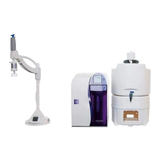
Summary of Contents for Millipore Milli-Q Integral 3
- Page 1 User Manual Milli-Q Integral 3/5/10/15 Systems...
- Page 2 Water Purification System. If this User Manual is not the correct one for your Water Purification System, then please contact Millipore . The term “Milli-Q Integral Water Purification System” is replaced by the Terminology term “Milli-Q System”...
- Page 3 Millipore Corporation assumes no responsibility for any errors that might appear in this document. This manual is believed to be complete and accurate at the time of publication. In no event shall Millipore Corporation be liable for incidental or consequential damages in connection with or arising from the use of this manual.
- Page 4 A10, Elix, Q-POD, Quantum, Milli-Q, Millipak and Progard are registered trademarks of Millipore Corporation. Millipore is a registered trademark of Millipore Corporation. The M mark is a trademark of Millipore Corporation. E-POD, BioPak, EDS-Pak and ROClean are trademarks of Millipore Corporation.
- Page 5 Do not remove the covers of the Milli-Q System at any time. Electrical and mechanical components inside the Milli-Q System could pose a hazard. A qualified Millipore Service Representative should perform any work that needs to be done while the Milli-Q System is opened.
- Page 6 Dispensing water ........................83 Printing ..........................86 Lab Closed feature ......................91 Viewing water quality ......................93 Viewing Operation ......................95 Viewing Consumable Status ....................98 Calling Millipore ......................100 Viewing Information ......................101 Maintenance ...........................103 Overview ..........................103 Maintenance Schedule......................104 Replacing the Progard Pack and Vent Filter ..............106 Replacing the Quantum Cartridge..................110...
- Page 7 Sanitising or cleaning the RO Cartridge(s) ..............119 Cleaning the Inlet Strainer....................124 Alarms.............................127 Overview ..........................127 Alarm Information......................128 Summary of Alarm messages...................133 Alerts............................139 Overview ..........................139 Alert information......................140 Summary of Alert messages.....................147 Ordering Information ......................152 Consumables, Accessories and Systems ................152...
- Page 8 Product Information Overview This chapter contains topics related to the Milli-Q System. Purpose Some of the more important topics in this chapter are: installation requirements, consumable information, and dimensions of various components of the Milli-Q System Contents This chapter contains the following topics: Topic See Page Cabinet...
- Page 9 Cabinet Overview Item Description/Name Main Display Connections for tubings, power cord, level sensor and other cables Progard Pack Quantum Cartridge Sanitisation Port The Main Display is used to navigate the Milli-Q System software. Main Display function Continued on next page...
- Page 10 Cabinet, Continued Details of the Main Display Item Description LEDs Green = No Alerts or Alarms Yellow = Alert Red = Alarm Main LCD Main Keypad The use of the Right Keypad button is shown below. In this example, the system is changed from STANDBY Mode to READY Mode.
- Page 11 Cabinet, Continued The use of the Left Keypad button is shown below. Left Diagram 1 Action Diagram 2 Press The use of the Up Keypad button is shown below. Diagram 1 Action Diagram 2 Press The use of the Down Keypad button is shown below. Down Diagram 1 Action...
- Page 12 Cabinet, Continued The use of the Validate Keypad button is shown below. Diagram 1 Action Diagram 2 Validate Press READY Mode The READY Mode screen display is explained below. – water quality This screen display shows the resistivity and temperature of the water filling values the Reservoir.
- Page 13 Cabinet, Continued LEDs The LEDs are described below. Item Description Green LED Milli-Q System is operating within specifications. Yellow LED An Alert is present. Red LED An Alarm is present. NOTE: If an Alarm and an Alert are present at the same time, then only the red LED is lit.
- Page 14 Cabinet, Continued Ports and cables Item Description Item Description RO Reject Port E-POD Unit (Accessory) Port Feedwater Port Reservoir Port Port for RC-Link to Q-POD Power Entry connection Unit (100 – 240 V) Port for RC-Link to Q-POD Accessories connection Unit (maximum 24 VDC) E-POD Unit (Accessory)
- Page 15 Q-POD Unit Overview Item Description Q-POD Plunger Point of Delivery POD Pak (BioPak Ultrafilter pictured here) Q-POD Arm Q-POD Mast Q-POD Base Q-POD Display Q-POD Keypad Continued on next page...
- Page 16 Q-POD Unit, Continued Display The Q-POD Display is shown and explained here. Display - 1 STANDBY Mode is used only to access the Maintenance and Manager STANDBY and Menus. READY READY Mode is the normal mode for Milli-Q Water production and delivery.
- Page 17 Q-POD Unit, Continued Display – 4 Status of consumables Progard Pack out Progard Pack in use Progard Pack not in use UV Lamps off UV 185 nm Lamp on UV 254 nm Lamp on Quantum Cartridge out Quantum Cartridge in Quantum Cartridge not in use NOTE:...
- Page 18 Q-POD Unit, Continued Display – FLOW The Milli-Q System has dispensed AUTOSTOP beyond the POD FLOW STOP Alarm time. The FLOW AUTO STOP Steady Alarm is shown on the Main Display. Press the Q-POD Plunger all the way down and release. Display –...
- Page 19 Q-POD Unit, Continued Keypad The Q-POD Keypad is shown and explained here. Item Description Press to start Milli-Q Water Recirculation Decrease volume Press to start volumetric dispensing Increase volume Press to get Instant Quality printout (if a printer is connected to the Q-POD Unit) Connections Item Description...
- Page 20 Q-POD Unit, Continued Termination The Termination Plug (shown below) is connected next to the PS/2 cable on Plug the Q-POD Base. RC-Link The RC-Link is the set of tubings and the PS/2 cable inside a sheath. The RC-Link is 2.7 metres in length. Item Description PS/2 Cable...


Need help?
Do you have a question about the Milli-Q Integral 3 and is the answer not in the manual?
Questions and answers