Table of Contents
Advertisement
Advertisement
Chapters
Table of Contents

Related Manuals for Detroit Diesel DDEC VI


Summary of Contents for Detroit Diesel DDEC VI
- Page 3 This document is a guideline for qualified personnel. It is intended to be used by vehicle manufacturers and contains Detroit Diesel Corporation's recommendations for the ancillary systems supporting the Detroit Diesel engines covered by this document. The vehicle manufacturer is responsible for developing, designing, manufacturing and installing these systems, including component qualification.
- Page 5 DDEC VI ELECTRONIC CONTROLS APPLICATION AND INSTALLATION ABSTRACT DDEC VI offers engine controls and an extensive range of engine and vehicle options. The detail provided will facilitate the following: □ The selection of features and settings, based on individual applications □...
- Page 6 ABSTRACT All information subject to change without notice. (Rev. 01/07) 7SA827 0701 Copyright © 2007 DETROIT DIESEL CORPORATION...
-
Page 7: Table Of Contents
DDEC VI ELECTRONIC CONTROLS APPLICATION AND INSTALLATION TABLE OF CONTENTS INTRODUCTION ......................... SAFETY PRECAUTIONS ....................STANDS .......................... GLASSES ........................WELDING ........................WORK PLACE ....................... CLOTHING ........................ELECTRIC TOOLS ......................AIR ..........................DIAGNOSTIC TOOLS ..................... FLUIDS AND PRESSURE ....................2.10 BATTERIES ........................ - Page 8 RED STOP LAMP ....................... 3-108 RED STOP LAMP REQUIREMENTS AND GUIDELINES ........3-109 RED STOP LAMP WIRING .................. 3-109 3.7.3 DPF REGENERATION LAMP ................... 3-110 All information subject to change without notice. (Rev. 01/07) 7SA827 0701 Copyright © 2007 DETROIT DIESEL CORPORATION...
- Page 9 DDEC VI ELECTRONIC CONTROLS APPLICATION AND INSTALLATION DPF REGENERATION LAMP REQUIREMENTS AND GUIDELINES ....3-110 PROGRAMMING REQUIREMENTS AND FLEXIBILITY ........3-110 3.7.4 HIGH EXHAUST SYSTEM TEMPERATURE LAMP ..........3-111 HIGH EXHAUST SYSTEM TEMPERATURE LAMP REQUIREMENTS AND GUIDELINES ......................3-111 PROGRAMMING REQUIREMENTS AND FLEXIBILITY ........
- Page 10 INSTALLATION ..................... 4-18 PROGRAMMING REQUIREMENTS & FLEXIBILITY .......... 4-18 4.1.18 REGEN SWITCH ......................4-19 INSTALLATION ..................... 4-19 PROGRAMMING REQUIREMENTS AND FLEXIBILITY ........4-19 All information subject to change without notice. (Rev. 01/07) 7SA827 0701 Copyright © 2007 DETROIT DIESEL CORPORATION...
- Page 11 DDEC VI ELECTRONIC CONTROLS APPLICATION AND INSTALLATION 4.1.19 REMOTE THROTTLE SELECT SWITCH ..............4-20 INSTALLATION ..................... 4-20 PROGRAMMING REQUIREMENTS & FLEXIBILITY .......... 4-20 4.1.20 REMOTE PTO SWITCH ..................... 4-20 INSTALLATION ..................... 4-20 4.1.21 RPM FREEZE ......................4-21 INSTALLATION ..................... 4-21 PROGRAMMING REQUIREMENTS &...
- Page 12 ANALOG OUTPUTS – CPC ................... 4-49 4.4.1 PIN 3/05 – ANALOG OUTPUT ................... 4-49 4.4.2 PIN 3/06 – ANALOG OUTPUT ................... 4-49 viii All information subject to change without notice. (Rev. 01/07) 7SA827 0701 Copyright © 2007 DETROIT DIESEL CORPORATION...
- Page 13 DDEC VI ELECTRONIC CONTROLS APPLICATION AND INSTALLATION PROGRAMMING REQUIREMENTS AND FLEXIBILITY ........4-50 PWM OUTPUT — CPC ....................4-51 4.5.1 PWM OUTPUT — PIN 4/12 PWM SELECTION ............4-51 PROGRAMMING REQUIREMENTS AND FLEXIBILITY ........4-51 FEATURES ......................... ACCELERATION LIMITER .....................
- Page 14 SINGLE-SPEED FAN INSTALLATION ..............5-57 PROGRAMMING REQUIREMENTS AND FLEXIBILITY ........5-58 5.11.4 DUAL FANS (FAN TYPE 6) ..................5-60 DUAL FANS INSTALLATION ................5-61 All information subject to change without notice. (Rev. 01/07) 7SA827 0701 Copyright © 2007 DETROIT DIESEL CORPORATION...
- Page 15 DDEC VI ELECTRONIC CONTROLS APPLICATION AND INSTALLATION PROGRAMMING REQUIREMENTS AND FLEXIBILITY ........5-62 5.11.5 TWO-SPEED FAN ...................... 5-64 TWO-SPEED FAN INSTALLATION ..............5-65 PROGRAMMING REQUIREMENTS AND FLEXIBILITY ........5-66 5.11.6 VARIABLE SPEED FAN (FAN TYPE 3) WITHOUT FAN SPEED FEEDBACK ..
- Page 16 REMOTE ACCELERATOR CONTROL FOR PTO OR ALSG ......5-146 REMOTE ACCELERATOR CONTROL EXAMPLE ..........5-146 INSTALLATION ..................... 5-147 5.25.4 RPM FREEZEE ......................5-147 All information subject to change without notice. (Rev. 01/07) 7SA827 0701 Copyright © 2007 DETROIT DIESEL CORPORATION...
- Page 17 DDEC VI ELECTRONIC CONTROLS APPLICATION AND INSTALLATION 5.26 TRANSMISSION INTERFACE ..................5-149 5.26.1 MANUAL TRANSMISSIONS ..................5-149 PROGRAMMING REQUIREMENTS AND FLEXIBILITY ........5-149 5.26.2 MERCEDES AGS2 TRANSMISSION ................ 5-149 INSTALLATION ..................... 5-150 PROGRAMMING REQUIREMENTS AND FLEXIBILITY ........5-152 5.26.3 EATON TOP2 OPERATION ..................
- Page 18 VEP – VEHICLE ELECTRICAL POWER ............. 6-76 VH — VEHICLE HOURS ..................6-77 VI – VEHICLE IDENTIFICATION ................6-77 APPENDIX A: HARNESS WIRING DIAGRAMS ................All information subject to change without notice. (Rev. 01/07) 7SA827 0701 Copyright © 2007 DETROIT DIESEL CORPORATION...
- Page 19 DDEC VI ELECTRONIC CONTROLS APPLICATION AND INSTALLATION APPENDIX B: ACRONYMS ......................APPENDIX C: PARAMETER LIST ....................INDEX ............................INDEX-1 All information subject to change without notice. (Rev. 01/07) 7SA827 0701 Copyright © 2007 DETROIT DIESEL CORPORATION...
- Page 20 TABLE OF CONTENTS All information subject to change without notice. (Rev. 01/07) 7SA827 0701 Copyright © 2007 DETROIT DIESEL CORPORATION...
- Page 21 DDEC VI ELECTRONIC CONTROLS APPLICATION AND INSTALLATION LIST OF FIGURES Figure 3-1 Motor Control Module ..................Figure 3-2 Series 60 Engine 120–pin Connector and 21–pin Connector Tie-wrapped to Brackets ......................3-16 Figure 3-3 Aftertreatment Device ..................3-20 Figure 3-4 Typical Mounting Views of an Aftertreatment Device ........
- Page 22 Compression Brake and Exhaust Flap – MBE900 ..........5-31 Figure 5-9 Compression Brake and Brake Grate – MBE4000 ........... 5-34 Figure 5-10 Engine Brake for DDEC VI – Series 60 ............. 5-39 Figure 5-11 Key Switch Starter Control ................5-49 Figure 5-12 MCM Starter Control ..................
- Page 23 DDEC VI ELECTRONIC CONTROLS APPLICATION AND INSTALLATION LIST OF TABLES Table 2-1 The Correct Type of Fire Extinguisher ............... Table 3-1 MCM Connector – Series 60 (1 of 4) ..............Table 3-2 MCM Connector – Series 60 (2 of 4) ..............
-
Page 24: Table 3-13 21-Pin Connector To The Mcm
CPC Connector #4, 18–pin Connector, Key C ..........3-70 Table 3-86 21–Pin Connector to the MCM Part Numbers ........... 3-71 Table 3-87 31–pin MCM Pigtail Connector Part Numbers ..........3-71 All information subject to change without notice. (Rev. 01/07) 7SA827 0701 Copyright © 2007 DETROIT DIESEL CORPORATION... - Page 25 DDEC VI ELECTRONIC CONTROLS APPLICATION AND INSTALLATION Table 3-88 DDC Part Numbers for the DPF 10-pin and 2–pin Connector — Horizontal Mount ATD ....................... 3-71 Table 3-89 DDC Part Numbers for the DPF 10-pin Connector — Vertical Mount ATD ..
- Page 26 Table 5-6 Cruise Control Input Configuration ..............5-13 Table 5-7 Cruise Control Parameters ................5-14 Table 5-8 Instrument Panel Lamps ................... 5-16 xxii All information subject to change without notice. (Rev. 01/07) 7SA827 0701 Copyright © 2007 DETROIT DIESEL CORPORATION...
- Page 27 DDEC VI ELECTRONIC CONTROLS APPLICATION AND INSTALLATION Table 5-9 Flashing Fault Code Parameters ............... 5-18 Table 5-10 Dual Speed Axle Digital Input ................5-19 Table 5-11 Programming the Axle Ratios ................5-19 Table 5-12 MCM Configuration Parameter for Exhaust Flap Applications - MBE900 Engine ......................
- Page 28 Vehicle Speed Limiting Parameters ..............5-161 Table 5-90 VSS Anti-tampering Parameters ............... 5-163 Table 6-1 Identifiers Used by CPC ..................Table 6-2 Message Priority Assignments ................xxiv All information subject to change without notice. (Rev. 01/07) 7SA827 0701 Copyright © 2007 DETROIT DIESEL CORPORATION...
- Page 29 DDEC VI ELECTRONIC CONTROLS APPLICATION AND INSTALLATION Table 6-3 J1939 Source Address ..................6-28 Table C-1 DDEC VI Parameters ..................C-17 All information subject to change without notice. (Rev. 01/07) 7SA827 0701 Copyright © 2007 DETROIT DIESEL CORPORATION...
- Page 30 TABLE OF CONTENTS xxvi All information subject to change without notice. (Rev. 01/07) 7SA827 0701 Copyright © 2007 DETROIT DIESEL CORPORATION...
-
Page 31: Introduction
DDEC VI ELECTRONIC CONTROLS APPLICATION AND INSTALLATION INTRODUCTION DDEC VI is a system that monitors and determines all values required for the operation of the engine. A diagnostic interface is provided to connect to an external diagnosis tester. Besides the engine related sensors and the engine-resident control unit, the Motor Control Module (MCM), this system has a cab-mounted control unit for vehicle engine management, the Common Powertrain Controller (CPC). - Page 32 INTRODUCTION THIS PAGE INTENTIONALLY LEFT BLANK All information subject to change without notice. (Rev. 01/07) 7SA827 0701 Copyright © 2007 DETROIT DIESEL CORPORATION...
-
Page 33: Safety Precautions
DDEC VI ELECTRONIC CONTROLS APPLICATION AND INSTALLATION SAFETY PRECAUTIONS The following safety measures are essential when installing DDEC VI in a vehicle equipped with a Detroit Diesel engine. PERSONAL INJURY Diesel engine exhaust and some of its constituents are known to the State of California to cause cancer, birth defects, and other reproductive harm. -
Page 34: Welding
Eliminate the possibility of a fall by: □ Wiping up oil spills □ Keeping tools and parts off the floor A fall could result in a serious injury. All information subject to change without notice. (Rev. 01/07) 7SA827 0701 Copyright © 2007 DETROIT DIESEL CORPORATION... -
Page 35: Clothing
DDEC VI ELECTRONIC CONTROLS APPLICATION AND INSTALLATION After installation of the engine is complete: PERSONAL INJURY To avoid injury from rotating belts and fans, do not remove and discard safety guards. □ Reinstall all safety devices, guards or shields □ Check to be sure that all tools and equipment used to install the engine are removed from... -
Page 36: Air
To avoid injury from penetrating fluids, do not put your hands in front of fluid under pressure. Fluids under pressure can penetrate skin and clothing. All information subject to change without notice. (Rev. 01/07) 7SA827 0701 Copyright © 2007 DETROIT DIESEL CORPORATION... -
Page 37: Batteries
□ Apply baking soda or lime to help neutralize the acid. □ Flush your eyes with water. □ Get medical attention immediately. Always disconnect the battery cable before working on the Detroit Diesel Electronic Controls system. All information subject to change without notice. (Rev. 01/07) -
Page 38: Fire
This acid is extremely corrosive and, if touched by bare skin, may cause severe burns (the symptoms could be delayed for several hours). All information subject to change without notice. (Rev. 01/07) 7SA827 0701 Copyright © 2007 DETROIT DIESEL CORPORATION... -
Page 39: Hardware And Wiring
DDEC VI ELECTRONIC CONTROLS APPLICATION AND INSTALLATION HARDWARE AND WIRING Section Page MOTOR CONTROL MODULE ..............COMMON POWERTRAIN CONTROLLER ..........3-27 WIRES AND WIRING ................3-73 CONDUIT AND LOOM ................3-87 TAPE AND TAPING ................3-89 SENSORS ....................3-91 LAMPS ....................3-107 All information subject to change without notice. - Page 40 HARDWARE AND WIRING THIS PAGE INTENTIONALLY LEFT BLANK All information subject to change without notice. (Rev. 01/07) 7SA827 0701 Copyright © 2007 DETROIT DIESEL CORPORATION...
-
Page 41: Motor Control Module
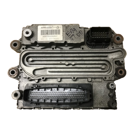
DDEC VI ELECTRONIC CONTROLS APPLICATION AND INSTALLATION MOTOR CONTROL MODULE The engine mounted Motor Control Module (MCM) includes control logic to provide overall engine management. See Figure 3-1. 1. 21–pin Connector (OEM Responsibility) 2. 120–pin Connector (Detroit Diesel Responsibility) Figure 3-1... -
Page 42: Mcm 120-Pin Connector For Series 60 Engines
Needle Control Valve (cyl 1) - pin 2 MV_B1 START_B DOC Outlet Temp Sensor DPF Outlet Pressure Sensor Table 3-1 MCM Connector – Series 60 (1 of 4) All information subject to change without notice. (Rev. 01/07) 7SA827 0701 Copyright © 2007 DETROIT DIESEL CORPORATION... -
Page 43: Table 3-2 Mcm Connector - Series 60 (2 Of 4)
DDEC VI ELECTRONIC CONTROLS APPLICATION AND INSTALLATION Signal Type Function Connector PWM_5 PWM_7 Jake 1 PWM_6 Two-speed Fan or Variable Speed Fan PWM_8 PWM_10 PWM_9 PWM_11 PV_M Ground HSW2 SW_1 HSW1 DYN3_N CKP/TRS (-) DYN3 CKP/TRS (+) DYN2_N CMP/SRS (-) -
Page 44: Table 3-3 Mcm Connector - Series 60 (3 Of 4)
Intake Manifold Pressure Sensor SGND_P Sensor Ground DOC Inlet Temp Sensor Intake Air Throttle Valve Table 3-3 MCM Connector – Series 60 (3 of 4) All information subject to change without notice. (Rev. 01/07) 7SA827 0701 Copyright © 2007 DETROIT DIESEL CORPORATION... -
Page 45: Table 3-4 Mcm Connector - Series 60 (4 Of 4)
DDEC VI ELECTRONIC CONTROLS APPLICATION AND INSTALLATION Signal Type Function Connector PV_B1 Power Supply PWM_3 PV_B1 Power Supply PWM_4 PV_M SW_4 SW_5 SW_3 Single-speed Fan or Two-speed Fan SW_7 H_Out1 Intake Air Throttle (+) H_Out2 Intake Air Throttle (-) SGND... -
Page 46: Mcm 120-Pin Connector For Mbe 900 Engines
Injector Common (cyl 1) – pin 2 START_B DOC Outlet Temp Sensor DPF Outlet Pressure Sensor Table 3-5 MCM Connector – MBE 900 (1 of 4) – C Sample All information subject to change without notice. (Rev. 01/07) 7SA827 0701 Copyright © 2007 DETROIT DIESEL CORPORATION... -
Page 47: Table 3-6 Mcm Connector - Mbe 900 (2 Of 4) - C Sample
DDEC VI ELECTRONIC CONTROLS APPLICATION AND INSTALLATION Signal Type Function Connector PWM_5 PWM_7 Constant Throttle Valve PWM_6 Two-speed Fan or Variable Speed Fan PWM_8 PWM_10 PWM_9 PWM_11 PV_M Ground HSW2 Electrostatic Oil Separator SW_1 HSW1 Grid Heater DYN3_N DYN3 CKP (+) -
Page 48: Table 3-7 Mcm Connector - Mbe 900 (3 Of 4) - C Sample
Sensor Ground DOC Inlet Temp Sensor Intake Air Throttle Position Table 3-7 MCM Connector – MBE 900 (3 of 4) – C Sample 3-10 All information subject to change without notice. (Rev. 01/07) 7SA827 0701 Copyright © 2007 DETROIT DIESEL CORPORATION... -
Page 49: Table 3-8 Mcm Connector - Mbe 900 (4 Of 4) - C Sample
DDEC VI ELECTRONIC CONTROLS APPLICATION AND INSTALLATION Signal Type Function Connector PV_B1 Power Supply PWM_3 High Tech Grid Heater PV_B1 Power Supply PWM_4 PV_M Ground SW_4 Exhaust Brake SW_5 SW_3 Single-speed or Two-speed Fan SW_7 H_OUT1 Intake Air Throttle 5kHz (+) -
Page 50: Mcm 120-Pin Connector For Mbe 4000 Engines
START_B DOC Outlet Temp Sensor DPF Outlet Pressure Sensor Table 3-9 MCM Connector – MBE 4000 (1 of 4) – C Sample 3-12 All information subject to change without notice. (Rev. 01/07) 7SA827 0701 Copyright © 2007 DETROIT DIESEL CORPORATION... -
Page 51: Table 3-10 Mcm Connector - Mbe 4000 (2 Of 4) - C Sample
DDEC VI ELECTRONIC CONTROLS APPLICATION AND INSTALLATION Signal Type Function Connector PWM_5 PWM_7 Constant Throttle Valve PWM_6 Two-speed Fan or Variable Speed Fan PWM_8 PWM_10 Wastegate PWM_9 PWM_11 PV_M Ground HSW2 Electrostatic Oil Separator SW_1 HSW1 Grid Heater DYN3_N DYN3... -
Page 52: Table 3-11 Mcm Connector - Mbe 4000 (3 Of 4) - C Sample
Sensor Ground DOC Inlet Temp Sensor Intake Air Throttle Position Table 3-11 MCM Connector – MBE 4000 (3 of 4) – C Sample 3-14 All information subject to change without notice. (Rev. 01/07) 7SA827 0701 Copyright © 2007 DETROIT DIESEL CORPORATION... -
Page 53: Table 3-12 Mcm Connector - Mbe 4000 (4 Of 4) - C Sample
DDEC VI ELECTRONIC CONTROLS APPLICATION AND INSTALLATION Signal Type Function Connector PV_B1 Power Supply PWM_3 High Tech Grid Heater PV_B1 Power Supply PWM_4 PV_M Ground EPV1 SW_4 (Entry Shutoff Flap) SW_5 SW_3 Single-speed Fan or Two-speed Fan SW_7 H_OUT1 Intake Throttle Valve 5 kHz (+) -
Page 54: Connector Brackets
Series 60 engine (see Figure 3-2). Figure 3-2 Series 60 Engine 120–pin Connector and 21–pin Connector Tie-wrapped to Brackets 3-16 All information subject to change without notice. (Rev. 01/07) 7SA827 0701 Copyright © 2007 DETROIT DIESEL CORPORATION... -
Page 55: Mcm 21-Pin And 31-Pin Connectors
DDEC VI ELECTRONIC CONTROLS APPLICATION AND INSTALLATION MCM 21–pin and 31–pin Connectors The wiring for the VIH 21–pin to the MCM is listed in Table 3-13. The side of the connector shown is looking into the pins. Signal Type Function... -
Page 56: Table 3-15 31-Pin Mcm Pigtail Connector Part Numbers
The pinout for the 31–pin pigtail on the Engine Harness is listed in Table 3-16. The OEM is responsible for wiring to this connector. 3-18 All information subject to change without notice. (Rev. 01/07) 7SA827 0701 Copyright © 2007 DETROIT DIESEL CORPORATION... -
Page 57: Table 3-16 31-Pin Mcm Pigtail Connector
DDEC VI ELECTRONIC CONTROLS APPLICATION AND INSTALLATION 31–pin 120–pin Function Series 60 MBE 900 MBE 4000 31/1 — Spare — — — — — — — — 31/2 Power Supply (IGN)* — — 31/3 Fuel Heater Supply #1† 31/4 —... -
Page 58: Dpf Harness
3. DOC Outlet Temperature Sensor 7. A= Engine Exhaust Inlet 4. Sensor Junction Box 8. B= Exhaust Outlet Figure 3-3 Aftertreatment Device 3-20 All information subject to change without notice. (Rev. 01/07) 7SA827 0701 Copyright © 2007 DETROIT DIESEL CORPORATION... -
Page 59: Figure 3-4 Typical Mounting Views Of An Aftertreatment Device
DDEC VI ELECTRONIC CONTROLS APPLICATION AND INSTALLATION The ATD may be horizontally or vertically mounted depending on the vehicle chassis configuration. See Figure 3-4 for a typical mounting view of the ATD. Typical Mounting Views of an Aftertreatment Device Figure 3-4 The wiring for the DPF Harness is determined by the ATD mount position. -
Page 60: Dpf Harness - Vertical Mount Atd (31-Pin To 10 Pin Connector)
See Figure 3-5 for the DPF Harness wiring for vertical mount ATDs. Figure 3-5 Vertical and Under Step Mount ATD Wiring — OEM Responsibility 3-22 All information subject to change without notice. (Rev. 01/07) 7SA827 0701 Copyright © 2007 DETROIT DIESEL CORPORATION... -
Page 61: Table 3-17 Dpf 10-Pin Connector
DDEC VI ELECTRONIC CONTROLS APPLICATION AND INSTALLATION The wiring for the 10–pin DPF connector is listed in Table 3-17. The DDC part numbers for the DPF connector arelisted in Table 3-18. Function Connector Sensor Ground Sensor Supply DPF Inlet Pressure Sensor (Exhaust Gas Pressure... -
Page 62: Dpf Harness - Horizontal Mount Atd (31-Pin To 10-Pin Connector/2-Pin Connector)
Connector) See Figure 3-6 for the DPF Harness wiring for horizontal mount ATDs. Figure 3-6 Horizontal Mount ATD Wiring — OEM Responsibility 3-24 All information subject to change without notice. (Rev. 01/07) 7SA827 0701 Copyright © 2007 DETROIT DIESEL CORPORATION... -
Page 63: Table 3-19 Dpf 10-Pin Connector And 2-Pin Connector - Horizontal Mount Atd
DDEC VI ELECTRONIC CONTROLS APPLICATION AND INSTALLATION The wiring for the DPF 10–pin connector and 2–pin connector is listed in Table 3-19. The DDC part numbers for the DPF connector arelisted in Table 3-20. Function Connector Sensor Ground Sensor Supply... - Page 64 HARDWARE AND WIRING THIS PAGE INTENTIONALLY LEFT BLANK 3-26 All information subject to change without notice. (Rev. 01/07) 7SA827 0701 Copyright © 2007 DETROIT DIESEL CORPORATION...
-
Page 65: Common Powertrain Controller
DDEC VI ELECTRONIC CONTROLS APPLICATION AND INSTALLATION COMMON POWERTRAIN CONTROLLER The Common Powertrain Controller (CPC) has three 18–pin connectors and one 21–pin connector. The following sections contain the connector pin-outs for truck, vocational, transit bus, fire truck, and crane applications. -
Page 66: Figure 3-8 Cpc Dimensions
VIH. See Figure 3-8 for the CPC dimensions. Figure 3-8 CPC Dimensions NOTE: The CPC should be mounted with the connectors pointing down. 3-28 All information subject to change without notice. (Rev. 01/07) 7SA827 0701 Copyright © 2007 DETROIT DIESEL CORPORATION... -
Page 67: Environmental Conditions
DDEC VI ELECTRONIC CONTROLS APPLICATION AND INSTALLATION The CPC communicates over the J1587 and J1939 Data Links to the vehicle (see Figure 3-9). Figure 3-9 NAFTA Architecture On-highway Within the CPC, sets of data for specific applications are stored. These include idle speed, maximum running speed, and speed limitation. -
Page 68: Cpc Vehicle Interface Harness
The OEM supplied Vehicle Interface Harness (VIH) connects the CPC to the MCM and other vehicle systems (see Figure 3-10). Figure 3-10 Vehicle Interface Harness 3-30 All information subject to change without notice. (Rev. 01/07) 7SA827 0701 Copyright © 2007 DETROIT DIESEL CORPORATION... -
Page 69: Frequency Input
DDEC VI ELECTRONIC CONTROLS APPLICATION AND INSTALLATION The following criteria are to be used when designing the VIH. Criteria: VIH Design The four vehicle connectors are designed to accept 18 AWG wires for all circuits. The conductor must be annealed copper, not aluminum, and must comply with the industry standard SAE J1128 document. -
Page 70: Digital Inputs
≤ 800 mH (if valve or relay load) Capacity: ≤ 10 nF Isink: Capable of sinking less than or equal to 2.0 A 3-32 All information subject to change without notice. (Rev. 01/07) 7SA827 0701 Copyright © 2007 DETROIT DIESEL CORPORATION... - Page 71 DDEC VI ELECTRONIC CONTROLS APPLICATION AND INSTALLATION Low Power Outputs DO_HP_FLEX-1 – 1/13 DO_HP_FLEX_2 – 2/10 DO_HP_FLEX_3 — 3/10 DO_HP_FLEX_4 — 3/12 DO_HP_FLEX_5 — 3/16 DO_HP_FLEX_6 — 4/6 DO_HP_LS_01 — 1/4 DO_HP_LS_02 — 1/5 Low-side Low Power Output Characteristics: Resistance: 12 V - vehicle power: R >...
-
Page 72: Vih Wiring
013 545 76 26 CPC - socket 1.0-2.5mm wire (single) 013 545 78 26 Table 3-23 Connector #1, 18–pin Connector, B Key 3-34 All information subject to change without notice. (Rev. 01/07) 7SA827 0701 Copyright © 2007 DETROIT DIESEL CORPORATION... -
Page 73: Table 3-24 Connector #2 Pin Assignments - Truck Application
DDEC VI ELECTRONIC CONTROLS APPLICATION AND INSTALLATION The pin assignments for the Common Powertrain Controller (CPC) #2 connector (18–pins) for truck applications is listed in Table 3-24. The side of the connector shown is looking into the pins. The part numbers for the #2 connector, Key A and terminals are listed in Table 3-25. - Page 74 013 545 76 26 CPC - socket 1.0-2.5mm wire (single) 013 545 78 26 Table 3-27 Connector #3, 21–pin Connector, Key A 3-36 All information subject to change without notice. (Rev. 01/07) 7SA827 0701 Copyright © 2007 DETROIT DIESEL CORPORATION...
-
Page 75: Table 3-28 Connector #4 Pin Assignments - Truck Application
DDEC VI ELECTRONIC CONTROLS APPLICATION AND INSTALLATION The pin assignments for the Common Powertrain Controller (CPC) #4 connector (18–pins) for truck applications islisted in Table 3-28. The side of the connector shown is looking into the pins. The part numbers for the #4 connector, Key C and terminals are listed in Table 3-29. -
Page 76: Vocational Applications
013 545 76 26 CPC - socket 1.0-2.5mm wire (single) 013 545 78 26 Table 3-31 Connector #1, 18–pin Connector, B Key 3-38 All information subject to change without notice. (Rev. 01/07) 7SA827 0701 Copyright © 2007 DETROIT DIESEL CORPORATION... -
Page 77: Table 3-32 Connector #2 Pin Assignments - Vocational Applications
DDEC VI ELECTRONIC CONTROLS APPLICATION AND INSTALLATION The pin assignments for the Common Powertrain Controller (CPC) #2 connector (18–pin) for vocational applications are listed in Table 3-32. The side of the connector shown is looking into the pins. The part numbers for the #2 connector, Key A and terminals are listed in Table 3-33. - Page 78 013 545 76 26 CPC - socket 1.0-2.5mm wire (single) 013 545 78 26 Table 3-35 Connector #3, 21–pin Connector, Key A 3-40 All information subject to change without notice. (Rev. 01/07) 7SA827 0701 Copyright © 2007 DETROIT DIESEL CORPORATION...
- Page 79 DDEC VI ELECTRONIC CONTROLS APPLICATION AND INSTALLATION The pin assignments for the Common Powertrain Controller (CPC) #4 connector (18–pin) for vocational applications are listed in Table 3-36. The side of the connector shown is looking into the pins. The part numbers for the #4 connector, Key C and terminals are listed in Table 3-37.
-
Page 80: Coach Applications
013 545 76 26 CPC - socket 1.0-2.5mm wire (single) 013 545 78 26 Table 3-39 Connector #1, 18–pin Connector, B Key 3-42 All information subject to change without notice. (Rev. 01/07) 7SA827 0701 Copyright © 2007 DETROIT DIESEL CORPORATION... -
Page 81: Table 3-40 Connector #2 Pin Assignments - Coach Application
DDEC VI ELECTRONIC CONTROLS APPLICATION AND INSTALLATION The pin assignments for the Common Powertrain Controller (CPC) #2 connector (18–pin) for coach applications are listed in Table 3-40. The part numbers for the #2 connector, Key A and terminals are listed in Table 3-41. - Page 82 013 545 76 26 CPC - socket 1.0-2.5mm wire (single) 013 545 78 26 Table 3-43 Connector #3, 21–pin Connector, Key A 3-44 All information subject to change without notice. (Rev. 01/07) 7SA827 0701 Copyright © 2007 DETROIT DIESEL CORPORATION...
- Page 83 DDEC VI ELECTRONIC CONTROLS APPLICATION AND INSTALLATION The pin assignments for the Common Powertrain Controller (CPC) #4 connector (18–pin) for coach applications are listed in Table 3-44. The part numbers for the #4 connector, Key C and terminals are listed in Table 3-45.
-
Page 84: Fire Truck Applications
013 545 76 26 CPC - socket 1.0-2.5mm wire (single) 013 545 78 26 Table 3-47 Connector #1, 18–pin Connector, B Key 3-46 All information subject to change without notice. (Rev. 01/07) 7SA827 0701 Copyright © 2007 DETROIT DIESEL CORPORATION... - Page 85 DDEC VI ELECTRONIC CONTROLS APPLICATION AND INSTALLATION The pin assignments for the Common Powertrain Controller #2 connector (18–pin) for fire truck applications are listed in Table 3-48. The part numbers for the #2 connector, Key A and terminals are listed in Table 3-49.
- Page 86 013 545 76 26 CPC - socket 1.0-2.5mm wire (single) 013 545 78 26 Table 3-51 Connector #3, 21–pin Connector, Key A 3-48 All information subject to change without notice. (Rev. 01/07) 7SA827 0701 Copyright © 2007 DETROIT DIESEL CORPORATION...
- Page 87 DDEC VI ELECTRONIC CONTROLS APPLICATION AND INSTALLATION The pin assignments for the Common Powertrain Controller #4 connector (18–pin) for fire truck applications are listed in Table 3-52. The part numbers for the #4 connector, Key C and terminals are listed in Table 3-53.
-
Page 88: Crane Applications
013 545 76 26 CPC - socket 1.0-2.5mm wire (single) 013 545 78 26 Table 3-55 Connector #1, 18–pin Connector, B Key 3-50 All information subject to change without notice. (Rev. 01/07) 7SA827 0701 Copyright © 2007 DETROIT DIESEL CORPORATION... - Page 89 DDEC VI ELECTRONIC CONTROLS APPLICATION AND INSTALLATION The pin assignments for the Common Powertrain Controller #2 connector (18–pin) for crane applications are listed in Table 3-56. The part numbers for the #2 connector, Key A and terminals are listed in Table 3-57.
- Page 90 013 545 76 26 CPC - socket 1.0-2.5mm wire (single) 013 545 78 26 Table 3-59 Connector #3, 21–pin Connector, Key A 3-52 All information subject to change without notice. (Rev. 01/07) 7SA827 0701 Copyright © 2007 DETROIT DIESEL CORPORATION...
- Page 91 DDEC VI ELECTRONIC CONTROLS APPLICATION AND INSTALLATION The pin assignments for the Common Powertrain Controller #4 connector (18–pin) for crane applications are listed in Table 3-60 The part numbers for the #4 connector, Key C and terminals are listed in Table 3-61.
-
Page 92: Transit Bus Applications
013 545 76 26 CPC - socket 1.0-2.5mm wire (single) 013 545 78 26 Table 3-63 Connector #1, 18–pin Connector, B Key 3-54 All information subject to change without notice. (Rev. 01/07) 7SA827 0701 Copyright © 2007 DETROIT DIESEL CORPORATION... - Page 93 DDEC VI ELECTRONIC CONTROLS APPLICATION AND INSTALLATION The pin assignments for the Common Powertrain Controller (CPC) #2 connector (18–pin) for transit bus applications are listed in Table 3-64. The part numbers for the #2 connector, Key A and terminals are listed in Table 3-65.
- Page 94 013 545 76 26 CPC - socket 1.0-2.5mm wire (single) 013 545 78 26 Table 3-67 Connector #3, 21–pin Connector, Key A 3-56 All information subject to change without notice. (Rev. 01/07) 7SA827 0701 Copyright © 2007 DETROIT DIESEL CORPORATION...
- Page 95 DDEC VI ELECTRONIC CONTROLS APPLICATION AND INSTALLATION The pin assignments for the Common Powertrain Controller (CPC) #4 connector (18–pin) for transit bus applications are Table 3-66, and listed in Table 3-68. The part numbers for the #4 connector, Key C and terminals are listed in Table 3-69.
-
Page 96: Vih To Mcm Connector Wiring
000 545 28 39 Backshell 001 545 79 83 Cavity Plug 000 545 62 80 Table 3-71 21–Pin Connector to the MCM Part Numbers 3-58 All information subject to change without notice. (Rev. 01/07) 7SA827 0701 Copyright © 2007 DETROIT DIESEL CORPORATION... - Page 97 DDEC VI ELECTRONIC CONTROLS APPLICATION AND INSTALLATION The part numbers for the 31–pin MCM pigtail connector are listed in Table 3-72. Part DDC Part Number Connector 008 545 31 26 Terminal 006 545 52 26 Seals 000 545 72 80...
- Page 98 † Optional for MBE 900 and HDE. Must use 14 AWG wire and fuse at 20A. Table 3-73 31–pin MCM Pigtail Connector 3-60 All information subject to change without notice. (Rev. 01/07) 7SA827 0701 Copyright © 2007 DETROIT DIESEL CORPORATION...
-
Page 99: Vih Power Wiring
DDEC VI ELECTRONIC CONTROLS APPLICATION AND INSTALLATION VIH Power Wiring The OEM-supplied VIH power wiring (see Figure 3-11) supplies 12 volts to the CPC and MCM. The system must be sourced directly from the battery. The terminals are designed to accept 14 AWG wire with an insulation diameter of 3.2 mm minimum and 5.6 mm maximum. - Page 100 Splices must be soldered and sealed with a waterproof insulator. Alpha FIT-300, Raychem TAT-125 or any equivalent heat shrink - dual wall epoxy encapsulating adhesive polyolefin is required. Detroit Diesel Corporation recommends color coding. Alternatively, wires may be hot stamped with the cavity number. 3-62 All information subject to change without notice.
-
Page 101: Wire Resistances
DDEC VI ELECTRONIC CONTROLS APPLICATION AND INSTALLATION Wire Resistances VIH power terminals require 14 AWG wire. The total resistance of the power harness cannot exceed 60 mΩ. The characteristics for Teflon coated and GXL type wire gauges are listed in listed in Table 3-74. - Page 102 2200 U.S. 27 South Raychem Wire & Harnessing Richmond, IN 47374 300 Constitution Drive Phone: 1–800–235–3361 Menlo Park, CA 94025 www.belden.com www.raychem.com 3-64 All information subject to change without notice. (Rev. 01/07) 7SA827 0701 Copyright © 2007 DETROIT DIESEL CORPORATION...
-
Page 103: Communications - Proprietary Engine-Can Data Link
DDEC VI ELECTRONIC CONTROLS APPLICATION AND INSTALLATION Communications – Proprietary Engine-CAN Data Link The low speed proprietary Engine-CAN link between the MCM and the CPC must be a twisted shielded cable with 0.75 mm diameter wire (approximately 20 AWG), bundle shielded with drain wire and 30 twists per meter. -
Page 104: Average Current Draw
A battery isolator is not required. However, some applications require a battery that is dedicated to the engine and completely isolated from the rest of the vehicle. Commercially available battery isolators can be used. 3-66 All information subject to change without notice. (Rev. 01/07) 7SA827 0701 Copyright © 2007 DETROIT DIESEL CORPORATION... -
Page 105: Main Power Shutdown
DDEC VI ELECTRONIC CONTROLS APPLICATION AND INSTALLATION Main Power Shutdown The main power supply shutdown schematic shows the DDC approved method for main power switch implementation. See Figure 3-12. Figure 3-12 Main Power Supply Shutdown NOTE: Switches must remain closed for 30 seconds after ignition is off for the MCM and CPC to write non-volatile data. -
Page 106: Fuses
Additional loads may blow the fuse (or trip the circuit breaker) and cause the circuit to overheat and burn. 3-68 All information subject to change without notice. (Rev. 01/07) 7SA827 0701 Copyright © 2007 DETROIT DIESEL CORPORATION... - Page 107 DDEC VI ELECTRONIC CONTROLS APPLICATION AND INSTALLATION FIRE To avoid injury from fire, do not replace an existing fuse with a larger amperage fuse. The increased current may overheat the wiring, causing the insulation and surrounding materials to burn. The ignition fuse current rating must be sized for the loads utilized in each application; however, a rating of between 5 and 10 amps is usually sufficient.
-
Page 108: Connectors
013 545 76 26 CPC - socket 1.0-2.5mm wire (single) 013 545 78 26 Table 3-85 CPC Connector #4, 18–pin Connector, Key C 3-70 All information subject to change without notice. (Rev. 01/07) 7SA827 0701 Copyright © 2007 DETROIT DIESEL CORPORATION... - Page 109 DDEC VI ELECTRONIC CONTROLS APPLICATION AND INSTALLATION Part DDC Part Number Connector 024 545 76 26 1.0 – 2.5 mm Contact (single) 014 545 82 26 0.5 – 1.0 mm Contact (single) 014 545 83 26 Seal (2.2 – 3.0 mm...
-
Page 110: Data Link Connector
The SAE J1587/J1708 Data Link must be twisted pairs. The twists are a minimum of 12 turns per foot (305 mm). The maximum length for the SAE J1587/J1708 Data Link is 130 ft (40 m). 3-72 All information subject to change without notice. (Rev. 01/07) 7SA827 0701 Copyright © 2007 DETROIT DIESEL CORPORATION... -
Page 111: Wires And Wiring
DDC circuit numbers when conflicts exist. 3.3.2 GENERAL WIRE All wires used in conjunction with DDEC VI must meet the following criteria: NOTICE: DDC does not recommend using any type of terminal lubricant or grease compounds. These products may cause dirt or other harmful substances to be retained in the connector. -
Page 112: Crimp Tools
HDT-48-00 to assure gas tight connections. NOTICE: If a separate seal is required, be sure to install the seal onto the wire before stripping the insulation. 3-74 All information subject to change without notice. (Rev. 01/07) 7SA827 0701 Copyright © 2007 DETROIT DIESEL CORPORATION... -
Page 113: Figure 3-14 Setting Wire Gage Selector And Positioning The Contact
DDEC VI ELECTRONIC CONTROLS APPLICATION AND INSTALLATION Use the following instructions for installing Deutsch terminals: 1. Strip approximately .25 inch (6 mm) of insulation from the cable. 2. Remove the lock clip, raise the wire gage selector, and rotate the knob to the number matching the gage wire that is being used. -
Page 114: Deutsch Terminal Removal
Table 3-92. Tool Kent-Moore Part Number J–37451 Removing (12 AWG) Removing (16-18 AWG) J–34513-1 Table 3-92 Removal Tools for Deutsch Terminals 3-76 All information subject to change without notice. (Rev. 01/07) 7SA827 0701 Copyright © 2007 DETROIT DIESEL CORPORATION... -
Page 115: Figure 3-17 Removal Tool Position
DDEC VI ELECTRONIC CONTROLS APPLICATION AND INSTALLATION Remove Deutsch terminals as follows: 1. With the rear insert toward you, snap the appropriate size remover tool over the cable of contact to be removed. See Figure 3-17. Figure 3-17 Removal Tool Position 2. -
Page 116: Splicing Guidelines
No more than one strand in a 16 strand wire may be cut or missing. Use Sn 60 solder with rosin core flux. The exposed wire must be clean before the splice is soldered. 3-78 All information subject to change without notice. (Rev. 01/07) 7SA827 0701 Copyright © 2007 DETROIT DIESEL CORPORATION... -
Page 117: Figure 3-19 Positioning The Leads
DDEC VI ELECTRONIC CONTROLS APPLICATION AND INSTALLATION Soldering splice connectors is optional. To solder splice connectors: 1. Position the leads, so one overlaps the other. See Figure 3-19. Figure 3-19 Positioning the Leads 2. Secure the leads with a commercially available clip and hand tool. See Figure 3-20. -
Page 118: Splicing And Repairing Straight Leads-Alternate Method 1
Terminal Crimper for Weather Pack Kent-Moore J–35606 Kent-Moore J–34182 Terminal Crimper for Deutsch Terminal Crimper for Metri-Pack 150 Kent-Moore J–35123 Table 3-95 Recommended Splicing Tools 3-80 All information subject to change without notice. (Rev. 01/07) 7SA827 0701 Copyright © 2007 DETROIT DIESEL CORPORATION... - Page 119 DDEC VI ELECTRONIC CONTROLS APPLICATION AND INSTALLATION Criteria: Splicing Straight Leads No more than one strand in a 16 strand wire may be cut or missing. The recommended method to splice straight leads follows: 1. Locate broken wire. 2. Remove insulation as required; be sure exposed wire is clean and not corroded.
-
Page 120: Figure 3-22 Splicing Straight Leads - Alternate Method
HARDWARE AND WIRING Figure 3-22 Splicing Straight Leads - Alternate Method 1 3-82 All information subject to change without notice. (Rev. 01/07) 7SA827 0701 Copyright © 2007 DETROIT DIESEL CORPORATION... -
Page 121: Splicing And Repairing Straight Leads - Alternate Method 2
DDEC VI ELECTRONIC CONTROLS APPLICATION AND INSTALLATION Splicing and Repairing Straight Leads - Alternate Method 2 This method is not allowed or recommended for power or ignition circuits. The tools required are listed in Table 3-97. Tool Part Number Heat Gun Wire Stripper Kent-Moore J–35615 or equivalent... -
Page 122: Figure 3-23 Splicing Straight Leads - Alternate Method
9. Loop the lead back over the spliced joint and tape. See Figure 3-21. Figure 3-23 Splicing Straight Leads - Alternate Method 2 3-84 All information subject to change without notice. (Rev. 01/07) 7SA827 0701 Copyright © 2007 DETROIT DIESEL CORPORATION... -
Page 123: Shrink Wrap
DDEC VI ELECTRONIC CONTROLS APPLICATION AND INSTALLATION Shrink Wrap Shrink wrap is required when splicing non insulated connections. Raychem HTAT or any equivalent heat shrink dual wall epoxy encapsulating adhesive polyolefin is required. Shrink wrap must extend at least .25 in. (6 mm) over wire insulation past splice in both directions. -
Page 124: Staggering Wire Splices
2. Heat shrink a minimum of two layers of heat shrink tubing. 3. Tape the spliced wires to each other. Refer to section 3.4. 3-86 All information subject to change without notice. (Rev. 01/07) 7SA827 0701 Copyright © 2007 DETROIT DIESEL CORPORATION... -
Page 125: Conduit And Loom
DDEC VI ELECTRONIC CONTROLS APPLICATION AND INSTALLATION CONDUIT AND LOOM Conduit must be used to protect the harness cable and cable splices. NOTICE: The conduit must not cover any connectors, switches, relays, fuses, or sensors. The following guidelines should be used when designing a harness:... - Page 126 HARDWARE AND WIRING THIS PAGE INTENTIONALLY LEFT BLANK 3-88 All information subject to change without notice. (Rev. 01/07) 7SA827 0701 Copyright © 2007 DETROIT DIESEL CORPORATION...
-
Page 127: Tape And Taping
DDEC VI ELECTRONIC CONTROLS APPLICATION AND INSTALLATION TAPE AND TAPING Tape must be used when conduit is utilized. Be sure to follow the tape manufacturers' guidelines. The harness manufacturer may use tape under the harness covering (conduit or loom) to facilitate harness building. - Page 128 HARDWARE AND WIRING THIS PAGE INTENTIONALLY LEFT BLANK 3-90 All information subject to change without notice. (Rev. 01/07) 7SA827 0701 Copyright © 2007 DETROIT DIESEL CORPORATION...
-
Page 129: Sensors
DDEC VI ELECTRONIC CONTROLS APPLICATION AND INSTALLATION SENSORS DDEC is designed to operate with several types of sensors as listed in Table 3-98. Sensor Type Description Used to monitor the crankshaft position, engine speed, turbo Variable Reluctance/Magnetic Pick-up speed, and vehicle speed. -
Page 130: Factory-Installed Sensors
Detects water in the fuel filter that alerts the owner/driver that the (MBE 900 only) fuel filter needs to be dried out. Table 3-99 Function of Factory-installed Sensors 3-92 All information subject to change without notice. (Rev. 01/07) 7SA827 0701 Copyright © 2007 DETROIT DIESEL CORPORATION... -
Page 131: Figure 3-25 Sensor Location For The Doc And Dpf
DDEC VI ELECTRONIC CONTROLS APPLICATION AND INSTALLATION See Figure 3-25 for the location of the sensors for the DOC and DPF. Figure 3-25 Sensor Location for the DOC and DPF 3-93 All information subject to change without notice. (Rev. 01/07) -
Page 132: Oem-Installed Sensors
The OEM harness must be securely fastened every six (6) in. It is required that the harness be fastened within six (6) in. of the sensor. 3-94 All information subject to change without notice. (Rev. 01/07) 7SA827 0701 Copyright © 2007 DETROIT DIESEL CORPORATION... -
Page 133: Ambient Air Temperature Sensor
DDEC VI ELECTRONIC CONTROLS APPLICATION AND INSTALLATION 3.6.3 AMBIENT AIR TEMPERATURE SENSOR The AAT Sensor is a thermistor type sensor with a variable resistance that produces an analog signal between 0 and 5 V, representing the temperature of the ambient air. The AAT Sensor (see Figure 3-26) is used with the Idle Shutdown Timer, specifically for the Ambient Air... -
Page 134: Ambient Air Temperature Sensor Installation
3 – J1587 4 – ECAN MID for Ambient 0 — 255 VEPS, DRS Air Temp Table 3-101 Ambient Air Temperature Sensor Parameters 3-96 All information subject to change without notice. (Rev. 01/07) 7SA827 0701 Copyright © 2007 DETROIT DIESEL CORPORATION... -
Page 135: Engine Coolant Level Sensor
DDEC VI ELECTRONIC CONTROLS APPLICATION AND INSTALLATION 3.6.4 ENGINE COOLANT LEVEL SENSOR The ECL Sensor provides an input to the engine protection system and warn the operator if a low coolant level has been reached. NOTE: This sensor is required. -
Page 136: Figure 3-29 Engine Coolant Level Sensor Installation For Cpc
The OEM must connect the ECL Sensor probe as shown in the next illustration (see Figure 3-29). Polarity of the ground and signal must be correct for proper operation. Figure 3-29 Engine Coolant Level Sensor Installation for CPC 3-98 All information subject to change without notice. (Rev. 01/07) 7SA827 0701 Copyright © 2007 DETROIT DIESEL CORPORATION... -
Page 137: Figure 3-30 Engine Coolant Level Sensor Location - Top Of Radiator Tank
DDEC VI ELECTRONIC CONTROLS APPLICATION AND INSTALLATION The probe should be located in either the radiator top tank or a remote mounted surge tank. It should be mounted horizontally in the center of the tank and must be in a position to signal low coolant before aeration occurs. - Page 138 Gentec 4 = Single Level Probe Sensor, fixed threshold * Not supported in NAFTA Table 3-105 Enabling the Engine Coolant Level Sensor 3-100 All information subject to change without notice. (Rev. 01/07) 7SA827 0701 Copyright © 2007 DETROIT DIESEL CORPORATION...
-
Page 139: Turbo Compressor In Temperature Sensor
DDEC VI ELECTRONIC CONTROLS APPLICATION AND INSTALLATION 3.6.5 TURBO COMPRESSOR IN TEMPERATURE SENSOR The TCI Sensor produces a signal representing the temperature of the turbo compressor inlet. See Figure 3-31 and Figure 3-32 for installation. NOTE: This sensor is required for the Series 60. -
Page 140: Vehicle Speed Sensor
Cruise Control and Vehicle Speed Limiting. The VSS signal type can be changed. NOTE: DDC does not approve of the use of signal generator sensors. Figure 3-33 Vehicle Speed Sensor 3-102 All information subject to change without notice. (Rev. 01/07) 7SA827 0701 Copyright © 2007 DETROIT DIESEL CORPORATION... -
Page 141: Magnetic Pickup
DDEC VI ELECTRONIC CONTROLS APPLICATION AND INSTALLATION To obtain accurate vehicle mileage, the parameters listed in Table 3-106 must be programmed with VEPS, DRS, or DDDL 7.0. Parameter Parameter Range Default Group 0 = No Sensor 1 = C3 Sensor... -
Page 142: Figure 3-34 Magnetic Vehicle Speed Sensor Installation - Cpc
HARDWARE AND WIRING See Figure 3-34 for the installation of the Magnetic VSS. Figure 3-34 Magnetic Vehicle Speed Sensor Installation – CPC 3-104 All information subject to change without notice. (Rev. 01/07) 7SA827 0701 Copyright © 2007 DETROIT DIESEL CORPORATION... -
Page 143: Sae J1939 Data Link
DDEC VI ELECTRONIC CONTROLS APPLICATION AND INSTALLATION SAE J1939 Data Link A VSS wired to the CPC is not required if the transmission output shaft speed message is being transmitted over the SAE J1939 Data Link. To obtain accurate vehicle mileage, the parameters listed in Table 3-109 must be programmed with VEPS. - Page 144 HARDWARE AND WIRING THIS PAGE INTENTIONALLY LEFT BLANK 3-106 All information subject to change without notice. (Rev. 01/07) 7SA827 0701 Copyright © 2007 DETROIT DIESEL CORPORATION...
-
Page 145: Lamps
DDEC VI ELECTRONIC CONTROLS APPLICATION AND INSTALLATION LAMPS The instrument panel warning lamps, the Amber Warning Lamp (AWL) and the Red Stop Lamp (RSL), are supplied by the OEM. The functionality of each lamp along with the wiring requirements are covered separately in the following sections. -
Page 146: Wiring Requirements
Figure 3-35 Amber Warning Lamp Wiring 3.7.2 RED STOP LAMP The RSL is controlled by DDEC VI. The RSL remains ON: □ For approximately five (5) seconds at the start of every ignition cycle (a bulb check) □ When a potential engine damaging fault is detected The RSL flashes:... -
Page 147: Red Stop Lamp Requirements And Guidelines
DDEC VI ELECTRONIC CONTROLS APPLICATION AND INSTALLATION Red Stop Lamp Requirements and Guidelines The following requirements and guidelines apply to the RSL: □ The RSL is required. □ A 12 volt light of less than 0.25 (DC) is required depending on the ignition source. Digital output circuits are designed to sink no more than 0.25 (DC) current. -
Page 148: Dpf Regeneration Lamp
HARDWARE AND WIRING 3.7.3 DPF REGENERATION LAMP This lamp is controlled by DDEC VI. The DPF Regeneration Lamp remains ON when □ Stationary regeneration is required. □ At the start of every ignition cycle, the lamp turns ON for approximately five (5) seconds (a bulb check). -
Page 149: High Exhaust System Temperature Lamp
DDEC VI ELECTRONIC CONTROLS APPLICATION AND INSTALLATION 3.7.4 HIGH EXHAUST SYSTEM TEMPERATURE LAMP The HEST Lamp is controlled by DDEC VI. The HEST Lamp remains ON: □ For approximately five (5) seconds at the start of every ignition cycle (a bulb check). -
Page 150: Malfunction Indicator Lamp
High Exhaust System Temperature Lamp Options 3.7.5 MALFUNCTION INDICATOR LAMP The Malfunction Indicator Lamp (MIL) is controlled by DDEC VI. The MIL remains ON: □ For approximately five (5) seconds at the start of every ignition cycle (a bulb check) □... -
Page 151: Low Oil Pressure Lamp
DDEC VI ELECTRONIC CONTROLS APPLICATION AND INSTALLATION 3.7.6 LOW OIL PRESSURE LAMP The Low Oil Pressure Lamp is controlled by DDEC VI.. The Low Oil Pressure Lamp remains ON: □ For approximately five (5) seconds at the start of every ignition cycle (a bulb check) □... -
Page 152: Cruise Active Lamp
HARDWARE AND WIRING 3.7.7 CRUISE ACTIVE LAMP The Cruise Active Lamp is controlled by DDEC VI.. The Cruise Active Lamp remains ON: □ For approximately five (5) seconds at the start of every ignition cycle (a bulb check) □ When Cruise Control is active... -
Page 153: Deceleration Lamp
DDEC VI ELECTRONIC CONTROLS APPLICATION AND INSTALLATION 3.7.8 DECELERATION LAMP The Deceleration Lamp is controlled by DDEC VI. The Deceleration Lamp remains ON: □ For approximately five (5) seconds at the start of every ignition cycle (a bulb check) □ When percent throttle is zero and Cruise Control is inactive... -
Page 154: Low Battery Voltage Lamp
HARDWARE AND WIRING 3.7.9 LOW BATTERY VOLTAGE LAMP The Low Battery Voltage Lamp is controlled by DDEC VI. The Low Battery Voltage Lamp remains ON: □ For approximately five (5) seconds at the start of every ignition cycle (a bulb check) □... -
Page 155: Low Coolant Level Lamp
DDEC VI ELECTRONIC CONTROLS APPLICATION AND INSTALLATION 3.7.10 LOW COOLANT LEVEL LAMP The Low Coolant Level Lamp is controlled by DDEC VI.. The Low Coolant Level Lamp remains ON: □ For approximately five (5) seconds at the start of every ignition cycle (a bulb check) □... -
Page 156: Optimized Idle Active Lamp
HARDWARE AND WIRING 3.7.11 OPTIMIZED IDLE ACTIVE LAMP The Optimized Idle Active Lamp is controlled by DDEC VI.. The Optimized Idle Active Lamp remains ON: □ For approximately five (5) seconds at the start of every ignition cycle (a bulb check) □... -
Page 157: Wait To Start Lamp
DDEC VI ELECTRONIC CONTROLS APPLICATION AND INSTALLATION 3.7.12 WAIT TO START LAMP The Wait to Start Lamp is controlled by DDEC VI.. The Wait to Start Lamp remains ON: □ For approximately five (5) seconds at the start of every ignition cycle (a bulb check) □... -
Page 158: Ags2 Backup Lamp
HARDWARE AND WIRING 3.7.13 AGS2 BACKUP LAMP The AGS2 Backup Lamp is controlled by DDEC VI. The AGS2 Backup Lamp remains ON: □ For approximately five (5) seconds at the start of every ignition cycle (a bulb check) □ When the AGS2 transmission is in reverse... -
Page 159: Ags2 Check Trans Lamp
DDEC VI ELECTRONIC CONTROLS APPLICATION AND INSTALLATION 3.7.14 AGS2 CHECK TRANS LAMP The AGS2 Check Trans Lamp is controlled by DDEC VI.. The AGS2 Check Trans Lamp remains ON: □ For approximately five (5) seconds at the start of every ignition cycle (a bulb check) □... -
Page 160: Ags2 Trans Temp Lamp
HARDWARE AND WIRING 3.7.15 AGS2 TRANS TEMP LAMP The AGS2 Trans Temp Lamp is controlled by DDEC VI.. The AGS2 Trans Temp Lamp remains ON: □ For approximately five (5) seconds at the start of every ignition cycle (a bulb check) □... - Page 161 DDEC VI ELECTRONIC CONTROLS APPLICATION AND INSTALLATION INPUTS AND OUTPUTS Section Page INPUTS ....................SWITCH INPUTS RECEIVED OVER J1939 DATA LINK ....... 4-27 DIGITAL OUTPUTS – CPC ..............4-29 ANALOG OUTPUTS – CPC ..............4-49 PWM OUTPUT — CPC ................
-
Page 162: Inputs And Outputs
INPUTS AND OUTPUTS THIS PAGE INTENTIONALLY LEFT BLANK All information subject to change without notice. (Rev. 01/07) 7SA827 0701 Copyright © 2007 DETROIT DIESEL CORPORATION... -
Page 163: Inputs
DDEC VI ELECTRONIC CONTROLS APPLICATION AND INSTALLATION INPUTS The input functions and their associated pins are listed in Table 4-1. Digital Input Functions CPC Connector / Pin A/C Status 2/12 ABS Active 3/18 Aux Shutdown #1 1/10 Clutch Released Switch... -
Page 164: Air Condition Status
VEPS or Enable Auto the fan when the 1 – Enable 1 – Enable A/C is on Table 4-2 Air Condition Status Programming Options All information subject to change without notice. (Rev. 01/07) 7SA827 0701 Copyright © 2007 DETROIT DIESEL CORPORATION... -
Page 165: Abs Active
DDEC VI ELECTRONIC CONTROLS APPLICATION AND INSTALLATION 4.1.2 ABS ACTIVE The anti-lock brake system (ABS) input is used with AGS2 transmissions for ABS indication to the CPC. Installation This switch is wired to pin 3/18 of the CPC. Programming Requirements and Flexibility The options for the ABS digital input are listed in Table 4-3. -
Page 166: Auxiliary Shutdown #1
1 — Enable Aux Shutdown Selection Shutdown Disable 2 — FUSO Accelerator Switch* * Not supported in NAFTA Table 4-4 Aux Shutdown #1 Programming Options All information subject to change without notice. (Rev. 01/07) 7SA827 0701 Copyright © 2007 DETROIT DIESEL CORPORATION... -
Page 167: Clutch Switch
DDEC VI ELECTRONIC CONTROLS APPLICATION AND INSTALLATION 4.1.4 CLUTCH SWITCH This input indicates that the clutch is released and is used for suspending Cruise Control and Auto Resume. When the clutch is released, the input is at battery ground. Cruise Control is suspended if the clutch is pressed once if Auto Resume is enabled. -
Page 168: Installation
1 – CCVS1 0 – Hardwired VEPS or DRS Config 2 – CCVS2 3 – CCVS3 Table 4-6 Cruise Control On/Off Switch Programming Options All information subject to change without notice. (Rev. 01/07) 7SA827 0701 Copyright © 2007 DETROIT DIESEL CORPORATION... -
Page 169: Cruise Control Resume/Accel Switch And Set/Coast Switch
DDEC VI ELECTRONIC CONTROLS APPLICATION AND INSTALLATION 4.1.6 CRUISE CONTROL RESUME/ACCEL SWITCH AND SET/COAST SWITCH RESUME – If Cruise Control has been disabled with the service brake or the clutch switch, momentary contact to the ON position (switching to battery ground) restores the previously set cruise speed. -
Page 170: Diagnostic Request Switch
flashing) 3 – Diagnostic Request Switch (fault code flashing) * Not supported in NAFTA Table 4-8 Diagnostic Request Switch Programming Options 4-10 All information subject to change without notice. (Rev. 01/07) 7SA827 0701 Copyright © 2007 DETROIT DIESEL CORPORATION... -
Page 171: Dual-Speed Axle Switch
DDEC VI ELECTRONIC CONTROLS APPLICATION AND INSTALLATION 4.1.8 DUAL-SPEED AXLE SWITCH This input indicates that the dual-speed axle ratio has been switched when the input is grounded. When the switch is open, the dual speed axle ratio is normal. The Dual-speed Axle Switch is a normally open switch. -
Page 172: Engine Brake Disable
The CPC, which controls the Engine Brake directly, will not allow engine braking when the input is switched to battery ground. DDEC VI supports the J1939 message to disable engine brake (TSC1 command to source address 15). -
Page 173: Engine Brake Low & Medium
DDEC VI ELECTRONIC CONTROLS APPLICATION AND INSTALLATION 4.1.10 ENGINE BRAKE LOW & MEDIUM The Engine Brake Low and Engine Brake Medium switches select the level of engine braking as listed in Table 4-11. Engine Brake Medium Engine Brake Low Digital Input... -
Page 174: Fast Engine Heat Up Switch
5 — Engine Brake Disable 6 — Fast Engine Heat Up Switch * Not supported in NAFTA Table 4-13 Fast Engine Heat Up Switch Programming Options 4-14 All information subject to change without notice. (Rev. 01/07) 7SA827 0701 Copyright © 2007 DETROIT DIESEL CORPORATION... -
Page 175: Idle Validation 1 & Idle Validation 2
DDEC VI ELECTRONIC CONTROLS APPLICATION AND INSTALLATION 4.1.13 IDLE VALIDATION 1 & IDLE VALIDATION 2 The Idle Validation Switch consists of two contacts. Idle Validation 1 is normally closed and indicates that the accelerator pedal is in the idle position when the input is grounded. Idle Validation 2 is normally open and indicates that the accelerator pedal is not in the idle position when it is grounded. -
Page 176: Optimized Idle Hood Tilt Switch
5 — Engine Brake Disable 6 — Fast Engine Heat Up Switch * Not supported in NAFTA Table 4-14 Hood Tilt Switch Programming Options 4-16 All information subject to change without notice. (Rev. 01/07) 7SA827 0701 Copyright © 2007 DETROIT DIESEL CORPORATION... -
Page 177: Optimized Idle Thermostat
DDEC VI ELECTRONIC CONTROLS APPLICATION AND INSTALLATION 4.1.16 OPTIMIZED IDLE THERMOSTAT The OI thermostat input indicates when the engine should run to heat/cool the cab when operating in Optimized Idle mode. This input is normally open. Installation The OI thermostat is wired to the CPC on pin 3/1. -
Page 178: Installation
0 – Hardwired 2 – CCVS2 3 – CCVS3 * Not supported in NAFTA Table 4-16 Configuring the Park Brake Switch Input 4-18 All information subject to change without notice. (Rev. 01/07) 7SA827 0701 Copyright © 2007 DETROIT DIESEL CORPORATION... -
Page 179: Regen Switch
DDEC VI ELECTRONIC CONTROLS APPLICATION AND INSTALLATION 4.1.18 REGEN SWITCH The Regen Switch is used by the operator to initiate a parked regeneration. If “DPF J1939 Regen SW Enable” is active, the CPC will no longer process the hardwired DPF Regen Switch requests. - Page 180 “PTO Throttle Override” is disabled. The Remote PTO Switch is a normally open switch. Installation This input is wired to the CPC pin 2/9. 4-20 All information subject to change without notice. (Rev. 01/07) 7SA827 0701 Copyright © 2007 DETROIT DIESEL CORPORATION...
- Page 181 DDEC VI ELECTRONIC CONTROLS APPLICATION AND INSTALLATION 4.1.21 RPM FREEZE The RPM Freeze input (when grounded) allows the operator to request that PTO maintain the current engine speed. Locking on to a fixed engine speed is desirable in applications where the input is subjected to electrical noise which in turn causes the engine speed to fluctuate.
- Page 182 1 – CCVS1 0 – Hardwired VEPS or DRS Config 2 – CCVS2 3 – CCVS3 Table 4-20 Configuring the Service Brake Switch Input 4-22 All information subject to change without notice. (Rev. 01/07) 7SA827 0701 Copyright © 2007 DETROIT DIESEL CORPORATION...
- Page 183 DDEC VI ELECTRONIC CONTROLS APPLICATION AND INSTALLATION 4.1.23 STOP ENGINE OVERRIDE The Stop Engine Override Switch is a momentary normally open switch. When the input is switched to battery ground, a shutdown override is enabled. Shutdown Override Switch is a momentary normally open switch.
- Page 184 1 — Info from J1939 0 – Hardwired VEPS or DRS Config 255 – Not Available Table 4-22 Configuring the Transmission Neutral Switch Input 4-24 All information subject to change without notice. (Rev. 01/07) 7SA827 0701 Copyright © 2007 DETROIT DIESEL CORPORATION...
- Page 185 DDEC VI ELECTRONIC CONTROLS APPLICATION AND INSTALLATION 4.1.26 TRANSMISSION RETARDER ACTIVE This input indicates that the transmission retarder is active. When the input is switched to ground, the fan is turned off. When the input is open, the fan will be turned on. The fan will be on for a minimum of 30 seconds.
- Page 186 INPUTS AND OUTPUTS THIS PAGE INTENTIONALLY LEFT BLANK 4-26 All information subject to change without notice. (Rev. 01/07) 7SA827 0701 Copyright © 2007 DETROIT DIESEL CORPORATION...
-
Page 187: Cruise Control
DDEC VI ELECTRONIC CONTROLS APPLICATION AND INSTALLATION SWITCH INPUTS RECEIVED OVER J1939 DATA LINK Multiplexing is available for several switch inputs over the SAE J1939 Data Link. The CPC supports this feature for the following switch inputs: □ Cruise Control On/Off Switch □... - Page 188 4 – CCVS1 or Hardwired 5 – CCVS2 or Hardwired 6 – CCVS1 or Hardwired * Not supported in NAFTA Table 4-25 Parameters for Multiplexing 4-28 All information subject to change without notice. (Rev. 01/07) 7SA827 0701 Copyright © 2007 DETROIT DIESEL CORPORATION...
- Page 189 DDEC VI ELECTRONIC CONTROLS APPLICATION AND INSTALLATION DIGITAL OUTPUTS – CPC The CPC has 15 digital output pins, 12 low side and three high side. The CPC digital output functions and their associated pins are listed in Table 4-26. Digital Output Function...
- Page 190 VEPS or — 0 – Disabled Detection 1 – Enabled * Not supported in NAFTA Table 4-28 AGS2 Backup Lamp Programming Options 4-30 All information subject to change without notice. (Rev. 01/07) 7SA827 0701 Copyright © 2007 DETROIT DIESEL CORPORATION...
- Page 191 DDEC VI ELECTRONIC CONTROLS APPLICATION AND INSTALLATION 4.3.2 AGS2 CHECK TRANS LAMP This digital output is used for non-multiplexed applications with the AGS2 transmission. Installation This digital output circuit is designed to sink no more that 250 mA (DC) current.
- Page 192 This digital output circuit is designed to sink no more than 250 mA (DC) current. The AWL is wired to pin 2/10 of the CPC. NOTE: This digital output is REQUIRED. 4-32 All information subject to change without notice. (Rev. 01/07) 7SA827 0701 Copyright © 2007 DETROIT DIESEL CORPORATION...
- Page 193 DDEC VI ELECTRONIC CONTROLS APPLICATION AND INSTALLATION 4.3.5 CRUISE ACTIVE LAMP When Cruise Control's Cruise Switch PTO is active, this digital output is switched to ground. This digital output can be used to drive a lamp indicating the active state of Cruise Control.
- Page 194 VEPS or DO Fault — 0 — Disabled 1 — Enabled Detection * Not supported in NAFTA Table 4-32 Deceleration Lamp Programming Options 4-34 All information subject to change without notice. (Rev. 01/07) 7SA827 0701 Copyright © 2007 DETROIT DIESEL CORPORATION...
- Page 195 DDEC VI ELECTRONIC CONTROLS APPLICATION AND INSTALLATION 4.3.7 DPF REGENERATION LAMP (HARDWIRED AND J1939) The purpose of this lamp is to let the operator know that a parked regeneration is required. This lamp can be hardwired or multiplexed. Solid illumination indicates a manual regeneration is required.
- Page 196 DO Fault — 0 – Disabled 1 — Enabled Detection * Not supported in NAFTA Table 4-34 Engine Brake Active Programming Options 4-36 All information subject to change without notice. (Rev. 01/07) 7SA827 0701 Copyright © 2007 DETROIT DIESEL CORPORATION...
- Page 197 DDEC VI ELECTRONIC CONTROLS APPLICATION AND INSTALLATION 4.3.9 ETHER START This digital output is switched to ground when ether should be injected into the engine for cold start purposes. NOTE: This output is used on a Series 60 engine only.
- Page 198 0 = Hardwired VEPS, DRS Lamp Config 1 = 1939 PTC1 * Not Available in NAFTA Table 4-36 High Exhaust System Temperature Lamp Options 4-38 All information subject to change without notice. (Rev. 01/07) 7SA827 0701 Copyright © 2007 DETROIT DIESEL CORPORATION...
- Page 199 DDEC VI ELECTRONIC CONTROLS APPLICATION AND INSTALLATION 4.3.11 LOW BATTERY VOLTAGE LAMP This digital output is switched to ground when a low battery voltage fault is detected. NOTE: This function is optional. Installation This digital output circuit is designed to sink no more than 2.0 A (DC) current.
- Page 200 DO Fault 0 – Disabled 1 — Enabled Detection * Not supported in NAFTA Table 4-38 Coolant Level Low Lamp Programming Options 4-40 All information subject to change without notice. (Rev. 01/07) 7SA827 0701 Copyright © 2007 DETROIT DIESEL CORPORATION...
- Page 201 DDEC VI ELECTRONIC CONTROLS APPLICATION AND INSTALLATION 4.3.13 LOW OIL PRESSURE LAMP This digital output is switched to ground when a low oil pressure fault is detected. NOTE: This function is optional. Installation This digital output circuit is designed to sink no more than 250 mA (DC) current.
- Page 202 Table 4-40 Optimized Idle Active Lamp Programming Options Diagnostics A Diagnostic Trouble Code (DTC) will be logged for an open or shorted circuit. 4-42 All information subject to change without notice. (Rev. 01/07) 7SA827 0701 Copyright © 2007 DETROIT DIESEL CORPORATION...
- Page 203 DDEC VI ELECTRONIC CONTROLS APPLICATION AND INSTALLATION 4.3.16 OPTIMIZED IDLE ALARM The Optimized Idle Alarm digital output is switched to sensor return to turn on the Optimized Idle Alarm. The alarm will sound for five seconds prior to any Optimized Idle engine start. For more information on Optimized Idle, refer to section 5.18, “Optimized Idle.”...
- Page 204 VEPS or DO Fault — 0 – Disabled 1 — Enabled Detection * Not supported in NAFTA Table 4-42 Starter Lockout Programming Options 4-44 All information subject to change without notice. (Rev. 01/07) 7SA827 0701 Copyright © 2007 DETROIT DIESEL CORPORATION...
- Page 205 DDEC VI ELECTRONIC CONTROLS APPLICATION AND INSTALLATION 4.3.19 TOP2 SHIFT SOLENOID The shift solenoid is used to command an automatic shift between the top two gears in an Eaton® Top2 transmission. When the digital output is switched to power, the shift solenoid commands a shift to the top gear position.
- Page 206 Table 4-44 Top2 Shift Lockout Solenoid Programming Options Diagnostics A Diagnostic Trouble Code (DTC) will be logged for an open or shorted circuit. 4-46 All information subject to change without notice. (Rev. 01/07) 7SA827 0701 Copyright © 2007 DETROIT DIESEL CORPORATION...
- Page 207 DDEC VI ELECTRONIC CONTROLS APPLICATION AND INSTALLATION 4.3.21 VEHICLE POWER SHUTDOWN This digital output actuates a relay that shuts down the rest of the electrical power to the vehicle when an idle shutdown or engine protection shutdown occurs. Installation The Vehicle Power Shutdown is wired to pin 4/10 of the CPC. This is a high side digital output.
- Page 208 VEPS or — 0 – Disabled Detection 1 — Enabled * Not supported in NAFTA Table 4-46 Wait to Start Lamp Programming Options 4-48 All information subject to change without notice. (Rev. 01/07) 7SA827 0701 Copyright © 2007 DETROIT DIESEL CORPORATION...
- Page 209 DDEC VI ELECTRONIC CONTROLS APPLICATION AND INSTALLATION ANALOG OUTPUTS – CPC The CPC has two analog outputs that can be used for various functions. 4.4.1 PIN 3/05 – ANALOG OUTPUT This pin can be configured for the functions listed in Table 4-47.
- Page 210 VEPS, DRS 2 – Coolant Temperature Gauge 3 – OI Thermostat Input* * Not supported in NAFTA Table 4-49 Analog Output Options 4-50 All information subject to change without notice. (Rev. 01/07) 7SA827 0701 Copyright © 2007 DETROIT DIESEL CORPORATION...
- Page 211 DDEC VI ELECTRONIC CONTROLS APPLICATION AND INSTALLATION PWM OUTPUT — CPC There is one PWM output on the CPC. 4.5.1 PWM OUTPUT — PIN 4/12 PWM SELECTION This selection is pin 4/12. This pin can be used for a Road Speed PWM output as listed in Table 4-50.
- Page 212 INPUTS AND OUTPUTS THIS PAGE INTENTIONALLY LEFT BLANK 4-52 All information subject to change without notice. (Rev. 01/07) 7SA827 0701 Copyright © 2007 DETROIT DIESEL CORPORATION...
- Page 213 DDEC VI ELECTRONIC CONTROLS APPLICATION AND INSTALLATION FEATURES Section Page ACCELERATION LIMITER ..............COLD START – MBE900 AND MBE4000 ..........CRUISE CONTROL ................DIAGNOSTICS ..................5-15 DUAL SPEED AXLE ................5-19 ENGINE BRAKE CONTROLS – MBE900 AND MBE4000 ..... 5-21 ENGINE BRAKE CONTROLS –...
- Page 214 5.25 THROTTLE CONTROL/GOVERNORS ..........5-133 5.26 TRANSMISSION INTERFACE ..............5-149 5.27 VEHICLE SPEED LIMITING ..............5-161 5.28 VEHICLE SPEED SENSOR ANTI-TAMPERING ........5-163 All information subject to change without notice. (Rev. 01/07) 7SA827 0701 Copyright © 2007 DETROIT DIESEL CORPORATION...
-
Page 215: Acceleration Limiter
DDEC VI ELECTRONIC CONTROLS APPLICATION AND INSTALLATION ACCELERATION LIMITER 5.1.1 PROGRAMMING REQUIREMENTS AND FLEXIBILITY The parameters and options for Acceleration Limiter are listed in Table 5-1. Series Parameter Parameter Description Options Default Access Group Setting Maximum engine Noise Max 1800... - Page 216 FEATURES THIS PAGE INTENTIONALLY LEFT BLANK All information subject to change without notice. (Rev. 01/07) 7SA827 0701 Copyright © 2007 DETROIT DIESEL CORPORATION...
-
Page 217: Operation
DDEC VI ELECTRONIC CONTROLS APPLICATION AND INSTALLATION COLD START – MBE900 AND MBE4000 The MCM has optional support for an electric Grid Heater for use as a cold start aid. The Grid Heater element is operated by a high current relay. If the heater is enabled, the MCM will turn the Grid Heater relay on and off as required. -
Page 218: Figure 5-1 Grid Heater - Mbe4000
Figure 5-3 for the heavy-duty engine. 1. Battery Ground 3. Battery Supply (+12 V) 2. Connector to MCM (included in on-engine harness) Figure 5-1 Grid Heater – MBE4000 All information subject to change without notice. (Rev. 01/07) 7SA827 0701 Copyright © 2007 DETROIT DIESEL CORPORATION... -
Page 219: Figure 5-2 Grid Heater - Mbe900
DDEC VI ELECTRONIC CONTROLS APPLICATION AND INSTALLATION 1. Battery Supply (+12 V) 3. Connector to MCM (included in on-engine harness) 2. Possible Battery Ground Connection Figure 5-2 Grid Heater – MBE900 1. Battery Ground 3. Battery Supply (+12 V) 2. Connector to MCM Figure 5-3 Grid Heater –... - Page 220 Cold Start is cancelled No increase of intake air manifold temperature during Cold Start is cancelled preheating state Table 5-4 Cold Start Failures and Action Taken All information subject to change without notice. (Rev. 01/07) 7SA827 0701 Copyright © 2007 DETROIT DIESEL CORPORATION...
-
Page 221: Cruise Control
DDEC VI ELECTRONIC CONTROLS APPLICATION AND INSTALLATION CRUISE CONTROL Cruise Control maintains a targeted speed (MPH) by increasing or decreasing fueling. The targeted speed can be selected and adjusted with dash-mounted switches. Up to five digital inputs are required (four for automatic transmission) for Cruise Control operation. A Vehicle Speed Sensor (VSS) or an output shaft speed message over the J1939 data link is required for Cruise Control. -
Page 222: Engine Brakes In Cruise Control (Optional)
Cruise Control. Holding the Set/Coast will decrease the set point by 1 mph (1.6 km/hr) per second. When released the Cruise Control set point will be at the current speed. 5-10 All information subject to change without notice. (Rev. 01/07) 7SA827 0701 Copyright © 2007 DETROIT DIESEL CORPORATION... -
Page 223: Resume / Accel
DDEC VI ELECTRONIC CONTROLS APPLICATION AND INSTALLATION Resume / Accel The Resume/Accel switch is a momentary switch. Resume: If Cruise Control has been disabled with the service brake or the clutch switch, momentary contact to the ON position (switching the input to battery ground) restores the previously set cruise speed. -
Page 224: Figure 5-4 Cruise Control Circuit
□ Vehicle Speed Sensor (or J1939) See Figure 5-4 for a diagram of the Cruise Control circuit. Figure 5-4 Cruise Control Circuit 5-12 All information subject to change without notice. (Rev. 01/07) 7SA827 0701 Copyright © 2007 DETROIT DIESEL CORPORATION... -
Page 225: Programming Requirements And Flexibility
DDEC VI ELECTRONIC CONTROLS APPLICATION AND INSTALLATION 5.3.3 PROGRAMMING REQUIREMENTS AND FLEXIBILITY To configure an engine for Cruise Control, the digital inputs listed in Table 5-6 must be selected. These parameters can be set with VEPS or DRS. Refer to section 4.1, “Digital Inputs,” for more information. -
Page 226: Interaction With Other Features
If LIM0 OR LIM1 are grounded and programmed for a vehicle speed limit, the “Cruise Max Set speed” will be limited to this value. 5-14 All information subject to change without notice. (Rev. 01/07) 7SA827 0701 Copyright © 2007 DETROIT DIESEL CORPORATION... -
Page 227: Diagnostics
DDEC VI ELECTRONIC CONTROLS APPLICATION AND INSTALLATION DIAGNOSTICS Diagnostics is a standard feature of DDEC VI. The purpose of this feature is to provide information for problem identification and problem solving in the form of a code. The MCM and CPC continuously perform self diagnostic checks and monitors the other system components. - Page 228 Lamp (MIL) illuminate at the same time of the shift. Call for service as the Amber Warning Lamp Table 5-8 Instrument Panel Lamps 5-16 All information subject to change without notice. (Rev. 01/07) 7SA827 0701 Copyright © 2007 DETROIT DIESEL CORPORATION...
-
Page 229: Flashing Fault Codes With Awl / Sel
DDEC VI ELECTRONIC CONTROLS APPLICATION AND INSTALLATION Flashing Fault Codes with AWL / SEL The Stop Engine Override (SEO)/Diagnostic Request Switch is used to activate the AWL/RSL to flash codes. Active codes are flashed on the RSL and inactive codes are flashed on the AWL. - Page 230 2 – CC Cancel* Request feature Request Switch 3 – Diagnostic Request Switch * Not available in NAFTA Table 5-9 Flashing Fault Code Parameters 5-18 All information subject to change without notice. (Rev. 01/07) 7SA827 0701 Copyright © 2007 DETROIT DIESEL CORPORATION...
-
Page 231: Programming Requirements & Flexibility
DDEC VI ELECTRONIC CONTROLS APPLICATION AND INSTALLATION DUAL SPEED AXLE The Dual Speed Axle feature allows a digital input to be configured to switch between two axle ratios for calculation of vehicle speed. 5.5.1 OPERATION When the digital input is open the first axle ratio will be used. When the switch is grounded, the second axle ratio will be used. - Page 232 FEATURES THIS PAGE INTENTIONALLY LEFT BLANK 5-20 All information subject to change without notice. (Rev. 01/07) 7SA827 0701 Copyright © 2007 DETROIT DIESEL CORPORATION...
-
Page 233: Engine Brake Controls - Mbe900 And Mbe4000
DDEC VI ELECTRONIC CONTROLS APPLICATION AND INSTALLATION ENGINE BRAKE CONTROLS – MBE900 AND MBE4000 The Engine Brake option converts a power-producing diesel engine into a power-absorbing air compressor. This is accomplished by opening the constant throttle valve over all cylinders near the top of the normal compression stroke and releasing the compressed cylinder charge to exhaust. -
Page 234: Cruise Control Or Road Speed Limit With Engine Brake
This option is required for most automatic transmissions. DDEC VI also supports the J1939 message to disable engine brakes (TSC1 command to source address 15). Engine Fan Braking The Engine Fan Braking option turns on the cooling fan when the engine brake level is high and DDEC fan control is enabled. - Page 235 5.6.2 PROGRAMMING REQUIREMENTS AND FLEXIBILITY Engine Brake must be specified at the time of engine order or by contacting Detroit Diesel Technical Service. Configuration for MBE900 Exhaust Flap Applications The MCM Exhaust Flap configuration parameters are listed in Table 5-12.
- Page 236 3 = AGS2 PTO Feedback Disable (Optional) 4 = RPM Freeze 5 = Engine Brake Disable 6 = Fast Engine Heat-up Switch 5-24 All information subject to change without notice. (Rev. 01/07) 7SA827 0701 Copyright © 2007 DETROIT DIESEL CORPORATION...
- Page 237 DDEC VI ELECTRONIC CONTROLS APPLICATION AND INSTALLATION Parameter Parameter Description Options Setting Access Group 0 = Hardwired Engine Brake 0 = Hard- VEPS or — 1 = Info from J1939 Switch Config wired 255 = Not Available 0 = Variable Controlled Brake...
- Page 238 80 = Decompression Valve & Exhaust for medium Flap braking 81 = Decompression Valve & Brake Gate or Jake Brake 3rd Stage 5-26 All information subject to change without notice. (Rev. 01/07) 7SA827 0701 Copyright © 2007 DETROIT DIESEL CORPORATION...
- Page 239 DDEC VI ELECTRONIC CONTROLS APPLICATION AND INSTALLATION Parameter Parameter Description Options Setting Access Group Factor Stage 2 determines VEPS or Factor Engine the amount 0 – 100% Brake of medium braking 0 = No Engine Brake 16 = Exhaust Flap Only...
- Page 240 CPC Configuration Parameter for Compression Brake Applications - MBE900 Engine See Figure 5-7 for the MBE900 compression brake only schematic. Figure 5-7 Compression Brake Only – MBE900 5-28 All information subject to change without notice. (Rev. 01/07) 7SA827 0701 Copyright © 2007 DETROIT DIESEL CORPORATION...
- Page 241 DDEC VI ELECTRONIC CONTROLS APPLICATION AND INSTALLATION Configuration for MBE900 Compression and Exhaust Brake Applications The MCM Compression and Exhaust Brake configuration parameters are listed in Table 5-16 . Parameter Parameter Setting Options Default Access Group 6 – Jake 0 – No Function...
- Page 242 0 = Hardwired 0 = Hard- VEPS or — Brake Switch 1 = Info from J1939 wired Config 255 = Not Available 5-30 All information subject to change without notice. (Rev. 01/07) 7SA827 0701 Copyright © 2007 DETROIT DIESEL CORPORATION...
- Page 243 DDEC VI ELECTRONIC CONTROLS APPLICATION AND INSTALLATION Descrip- Parameter Parameter Options Setting Access tion Group 0 = Variable Controlled Brake J1939 Steps 1 = 1 Step VEPS or — Engine 2 = Low/High Steps Low/High Brake 3 = Low/Med/High Steps Steps 255 = Not Configured...
- Page 244 80 = Decompression Valve & Exhaust Flap braking 81 = Decompression Valve & Brake Gate or Jake Brake 3rd Stage 5-32 All information subject to change without notice. (Rev. 01/07) 7SA827 0701 Copyright © 2007 DETROIT DIESEL CORPORATION...
- Page 245 DDEC VI ELECTRONIC CONTROLS APPLICATION AND INSTALLATION Parameter Parameter Description Options Settings Access Group Factor Stage 2 determines Factor VEPS or the amount 0 – 100% Engine of medium Brake braking 0 = No Engine Brake 16 = Exhaust Flap Only...
- Page 246 See Figure 5-9 for a schematic of the MBE4000 compression brake and brake gate. Figure 5-9 Compression Brake and Brake Grate – MBE4000 5-34 All information subject to change without notice. (Rev. 01/07) 7SA827 0701 Copyright © 2007 DETROIT DIESEL CORPORATION...
- Page 247 DDEC VI ELECTRONIC CONTROLS APPLICATION AND INSTALLATION Cruise Control of Engine Brake Option The parameters listed in Table 5-20 are options for the Engine Brake with Cruise Control. Parameter Parameter Description Options Default Access Group Allows the engine brake to be...
- Page 248 Minimum Vehicle Speed for Engine Brakes Option Table 5-24 5.6.3 INTERACTION WITH OTHER FEATURES DDEC VI will respond to requests from other vehicle systems via the J1939 data link to disable or enable engine brake. 5-36 All information subject to change without notice. (Rev. 01/07)
-
Page 249: Engine Brake Controls - Series
5.7.1 OPERATION A dash mounted On/Off Switch is used to enable the Engine Brake option. DDEC VI will directly control the engine brake solenoids and turbocharger VGT position to produce the desired low, medium, or high braking power. This braking power is based on the driver selected intensity switch for a Series 60 engine. - Page 250 This option is required for most automatic transmissions. DDEC VI also supports the J1939 message to disable engine brakes (TSC1 command to source address 15). Engine Brake Active The Engine Brake Active option uses a digital output that can be used to drive an Engine Brake Active lamp.
- Page 251 DDEC VI ELECTRONIC CONTROLS APPLICATION AND INSTALLATION 5.7.2 INSTALLATION See Figure 5-10 for a DDEC VI internal engine brake schematic. Figure 5-10 Engine Brake for DDEC VI – Series 60 5-39 All information subject to change without notice. (Rev. 01/07)
- Page 252 Gate or Jake Brake 3rd Stage Stage 3 Factor Factor determines the VEPS, 0 – 100% Engine amount of high braking Brake 5-40 All information subject to change without notice. (Rev. 01/07) 7SA827 0701 Copyright © 2007 DETROIT DIESEL CORPORATION...
- Page 253 DDEC VI ELECTRONIC CONTROLS APPLICATION AND INSTALLATION Parameter Parameter Description Options Settings Access Group 0 = No Engine Brake 16 = Exhaust Flap Only 17 = Jake Brake 2nd Stage Trans Mask 64 = Decompression Valve Only or VEPS, Engine —...
- Page 254 4 = Oil Temp High Lamp* 5 = FUSO Engine Brake Active Lamp* *Not Supported in NAFTA Table 5-27 Optional Digital Output for Engine Brakes 5-42 All information subject to change without notice. (Rev. 01/07) 7SA827 0701 Copyright © 2007 DETROIT DIESEL CORPORATION...
- Page 255 DDEC VI ELECTRONIC CONTROLS APPLICATION AND INSTALLATION The Engine Fan Braking option parameter is listed in Table 5-28. Parameter Parameter Description Options Default Group Provides additional engine braking by activating the DDEC controlled Eng Brake Enable fan whenever the engine brakes are...
- Page 256 FEATURES THIS PAGE INTENTIONALLY LEFT BLANK 5-44 All information subject to change without notice. (Rev. 01/07) 7SA827 0701 Copyright © 2007 DETROIT DIESEL CORPORATION...
-
Page 257: Engine Protection
5.8.1 OPERATION Engine Protection is a vital part of MCM/CPC programming and software. DDEC VI monitors coolant level, various pressures and temperatures, and compares these parameters against the allowable limits to determine when a critical fault is reached. The AWL is illuminated and a code logged if there is an electronic system fault. - Page 258 5.8.2 STOP ENGINE OVERRIDE OPTION The Stop Engine Override Switch is used for a momentary override. DDEC VI will record the number of times the override is activated after a fault occurs. Momentary Override - An SEO switch is used to override the shutdown sequence. This override resets the 60 second (30 seconds for oil pressure) shutdown timer.
- Page 259 DDEC VI ELECTRONIC CONTROLS APPLICATION AND INSTALLATION 5.8.3 PROGRAMMING FLEXIBILITY DDEC VI is programmed with pressure, temperature, and level protection limits for each parameter monitored. Rampdown is always enabled. Shutdown can be configured for certain parameters. DDEC VI engine protection system parameters are listed in Table 5-31 .
- Page 260 FEATURES THIS PAGE INTENTIONALLY LEFT BLANK 5-48 All information subject to change without notice. (Rev. 01/07) 7SA827 0701 Copyright © 2007 DETROIT DIESEL CORPORATION...
-
Page 261: Engine Starter Control
DDEC VI ELECTRONIC CONTROLS APPLICATION AND INSTALLATION ENGINE STARTER CONTROL Engine starters may be enabled by either the ignition-run key switch (KL-50) (see Figure 5-11) or the MCM (see Figure 5-12). Figure 5-11 Key Switch Starter Control Figure 5-12 MCM Starter Control 5-49 All information subject to change without notice. - Page 262 If the parameter is set for MCM Starter Control and the starter is wired for Key Switch control, the engine will crank but will not start. 5-50 All information subject to change without notice. (Rev. 01/07) 7SA827 0701 Copyright © 2007 DETROIT DIESEL CORPORATION...
-
Page 263: Ether Starting - Series
DDEC VI ELECTRONIC CONTROLS APPLICATION AND INSTALLATION 5.10 ETHER STARTING – SERIES 60 Information not available at this time. 5-51 All information subject to change without notice. (Rev. 01/07) 7SA827 0701 Copyright © 2007 DETROIT DIESEL CORPORATION... - Page 264 FEATURES THIS PAGE INTENTIONALLY LEFT BLANK 5-52 All information subject to change without notice. (Rev. 01/07) 7SA827 0701 Copyright © 2007 DETROIT DIESEL CORPORATION...
-
Page 265: Fan Control
The purpose of the Fan Control feature is to electronically control engine cooling fan activation and to provide a load for vehicle retardation, when required. DDEC VI Fan Controls are designed to optimally control the engine cooling fan(s) based on engine cooling requirements. - Page 266 □ Fan Control Override Switch is grounded (ON) □ PTO is enabled and active – optional Single-Speed Fan Installation This section provides a schematic of the specific connection from DDEC VI to the fan. See Figure 5-13. Compatible fans may be obtained from several vendors. Figure 5-13 Single-speed Fan –...
- Page 267 DDEC VI ELECTRONIC CONTROLS APPLICATION AND INSTALLATION Programming Requirements and Flexibility The MCM options for the single-speed fan – Type 4 are listed in Table 5-33. Parameter Setting Options Default Access 0 = 2–Speed Fan with Ambient Temp Offset 1 = 2–Speed Fan...
- Page 268 A/C switch Active Open 3 = LIM Active Closed 4 = LIM Active Open Table 5-34 Single-speed Fan – Type 4 CPC Options 5-56 All information subject to change without notice. (Rev. 01/07) 7SA827 0701 Copyright © 2007 DETROIT DIESEL CORPORATION...
- Page 269 □ Fan Control Override Switch is grounded (ON) □ PTO is enabled and active – optional Single-Speed Fan Installation This section provides a schematic of the specific connection from DDEC VI to the fan. See Figure 5-14. Compatible fans may be obtained from several vendors. Figure 5-14 Single-speed Fan –...
- Page 270 17 = Single-speed Fan or Two-speed Fan 0 = No Function Fan or Two-speed VEPS, DRS Configuration Fan Low Table 5-35 Single-speed Fan – Type 7 MCM Options 5-58 All information subject to change without notice. (Rev. 01/07) 7SA827 0701 Copyright © 2007 DETROIT DIESEL CORPORATION...
- Page 271 DDEC VI ELECTRONIC CONTROLS APPLICATION AND INSTALLATION The CPC options for the single-speed fan – Type 7 are listed in Table 5-36. Parameter Parameter Description Access Options Default Group Enables/disables the 0 = Disable AC Fan Vehicle VEPS, road speed threshold...
- Page 272 □ Engine Brake level is active at high level – optional □ Fan control override switch is grounded (ON) □ PTO is enabled and active – optional 5-60 All information subject to change without notice. (Rev. 01/07) 7SA827 0701 Copyright © 2007 DETROIT DIESEL CORPORATION...
- Page 273 DDEC VI ELECTRONIC CONTROLS APPLICATION AND INSTALLATION Dual Fans Installation See Figure 5-15 for dual fan installation. Figure 5-15 Dual Fan (Fan Type 6) 5-61 All information subject to change without notice. (Rev. 01/07) 7SA827 0701 Copyright © 2007 DETROIT DIESEL CORPORATION...
- Page 274 VEPS, DRS Configuration 5 = Two-speed Fan High or PWM Fan PWM Fan Table 5-37 Dual Fan – Type 6 MCM Options 5-62 All information subject to change without notice. (Rev. 01/07) 7SA827 0701 Copyright © 2007 DETROIT DIESEL CORPORATION...
- Page 275 DDEC VI ELECTRONIC CONTROLS APPLICATION AND INSTALLATION The CPC options for the dual fan – Type 6 are listed in Table 5-38. Parameter Parameter Description Access Options Default Group AC Fan Vehicle Enables/disables the 0 = Disable VEPS, Speed Thresh...
- Page 276 □ Engine Brake level is active at high level □ Fan control override switch is enabled □ PTO enabled and active – optional 5-64 All information subject to change without notice. (Rev. 01/07) 7SA827 0701 Copyright © 2007 DETROIT DIESEL CORPORATION...
- Page 277 DDEC VI ELECTRONIC CONTROLS APPLICATION AND INSTALLATION Two-speed Fan Installation See Figure 5-16 for two-speed fan installation. Figure 5-16 Two-speed Fan ( Fan type 0 or 1) 5-65 All information subject to change without notice. (Rev. 01/07) 7SA827 0701 Copyright © 2007 DETROIT DIESEL CORPORATION...
- Page 278 VEPS, DRS Configuration 5 = Two-speed Fan High or PWM Fan PWM Fan Table 5-39 Two-speed Fan – Type 1 MCM Options 5-66 All information subject to change without notice. (Rev. 01/07) 7SA827 0701 Copyright © 2007 DETROIT DIESEL CORPORATION...
- Page 279 DDEC VI ELECTRONIC CONTROLS APPLICATION AND INSTALLATION The CPC options for the two-speed fan – Type 1 are listed in Table 5-40. Parameter Parameter Description Access Options Default Group AC Fan Vehicle Enables/disables the 0 = Disable VEPS, Speed Thresh...
- Page 280 VARIABLE SPEED FAN (FAN TYPE 3) WITHOUT FAN SPEED FEEDBACK DDEC VI uses a pulse width modulated (PWM) output to drive a variable speed fan. The fan may be enabled by specific engine temperature sensors and various other inputs. The fan will ramp up to the requested speed in order to reduce noise, shock-loading, and belt slippage.
- Page 281 DDEC VI ELECTRONIC CONTROLS APPLICATION AND INSTALLATION Installation See Figure 5-17 for variable-speed fan without fan speed feedback (Fan Type 3) installation. Figure 5-17 Variable Speed Fan without Fan Speed Feedback (Fan Type 3) 5-69 All information subject to change without notice. (Rev. 01/07)
- Page 282 5 = Two-speed Fan High or PWM Fan PWM Fan Table 5-41 Variable Speed Fan Without Fan Speed Feedback – Type 3 MCM Options 5-70 All information subject to change without notice. (Rev. 01/07) 7SA827 0701 Copyright © 2007 DETROIT DIESEL CORPORATION...
- Page 283 DDEC VI ELECTRONIC CONTROLS APPLICATION AND INSTALLATION The CPC options for the variable speed fan without fan speed feedback – Type 3 are listed in Table 5-42. Parameter Parameter Description Options Default Access Group AC Fan Vehicle Enables/disables the 0 = Disable...
- Page 284 VARIABLE SPEED FAN (FAN TYPE 2) WITH FAN SPEED FEEDBACK DDEC VI uses a pulse width modulated (PWM) output to drive a variable speed fan. The fan may be enabled by specific engine temperature sensors and various other inputs. The fan will ramp up to the requested speed in order to reduce noise, shock-loading, and belt slippage.
- Page 285 DDEC VI ELECTRONIC CONTROLS APPLICATION AND INSTALLATION Installation See Figure 5-18 for variable-speed fan with fan speed feedback (Fan Type 2) installation. Figure 5-18 Variable Speed Fan with Fan Speed Feedback (Fan Type 2) 5-73 All information subject to change without notice. (Rev. 01/07)
- Page 286 Type 2 Fan — Pulses Per 0 – 255 VEPS, DRS Table 5-43 Variable Speed Fan With Fan Speed Feedback – Type 2 Options 5-74 All information subject to change without notice. (Rev. 01/07) 7SA827 0701 Copyright © 2007 DETROIT DIESEL CORPORATION...
- Page 287 DDEC VI ELECTRONIC CONTROLS APPLICATION AND INSTALLATION The CPC options for the variable speed fan with fan speed feedback – Type 2 are listed in Table 5-44. Parameter Parameter Description Options Default Access Group AC Fan Vehicle Enables/disables the 0 = Disable...
- Page 288 FEATURES THIS PAGE INTENTIONALLY LEFT BLANK 5-76 All information subject to change without notice. (Rev. 01/07) 7SA827 0701 Copyright © 2007 DETROIT DIESEL CORPORATION...
-
Page 289: Fleet Management
DDEC VI ELECTRONIC CONTROLS APPLICATION AND INSTALLATION 5.12 FLEET MANAGEMENT The Fleet Management Products provide flexible data extraction and communication capabilities. DDEC Data collects the data (refer to section 5.12.2). DDEC Reports is the PC software for data analysis and reporting (refer to section 5.12.3). - Page 290 Enables/Disabled the VEPS, FM Fuel Density Fleet Management 0-65.535 0.835 DRS, DDDL fuel density data Table 5-45 DDEC Data Parameters for Fleet Management 5-78 All information subject to change without notice. (Rev. 01/07) 7SA827 0701 Copyright © 2007 DETROIT DIESEL CORPORATION...
- Page 291 DDEC VI ELECTRONIC CONTROLS APPLICATION AND INSTALLATION 5.12.3 DDEC REPORTS After the data is extracted, DDEC Reports software produces a wide range of diagnostic and management reports. DDEC Reports produces comprehensive trip reports in both on-highway and nonroad markets. The on-highway reports are: □...
- Page 292 FEATURES Figure 5-19 DDEC Reports, Trip Activity Report 5-80 All information subject to change without notice. (Rev. 01/07) 7SA827 0701 Copyright © 2007 DETROIT DIESEL CORPORATION...
- Page 293 DDEC VI ELECTRONIC CONTROLS APPLICATION AND INSTALLATION Figure 5-20 DDEC Reports, Daily Engine Usage 5-81 All information subject to change without notice. (Rev. 01/07) 7SA827 0701 Copyright © 2007 DETROIT DIESEL CORPORATION...
- Page 294 FEATURES Figure 5-21 DDEC Reports, Engine Load/RPM 5-82 All information subject to change without notice. (Rev. 01/07) 7SA827 0701 Copyright © 2007 DETROIT DIESEL CORPORATION...
- Page 295 DDEC VI ELECTRONIC CONTROLS APPLICATION AND INSTALLATION Figure 5-22 DDEC Reports, Vehicle Speed/RPM 5-83 All information subject to change without notice. (Rev. 01/07) 7SA827 0701 Copyright © 2007 DETROIT DIESEL CORPORATION...
- Page 296 FEATURES THIS PAGE INTENTIONALLY LEFT BLANK 5-84 All information subject to change without notice. (Rev. 01/07) 7SA827 0701 Copyright © 2007 DETROIT DIESEL CORPORATION...
-
Page 297: Fuel Economy Incentive
DDEC VI ELECTRONIC CONTROLS APPLICATION AND INSTALLATION 5.13 FUEL ECONOMY INCENTIVE The purpose of Fuel Economy Incentive (FEI) is to allow the fleet manager to set a fuel economy target while providing the driver an incentive to meet the target. - Page 298 Incentive is set for 7 MPH of extra speed when the driver hits the maximum fuel economy target and the same vehicle has a 5 MPH PasSmart increase, the resulting speed increase is 7 MPH, not 12 MPH. 5-86 All information subject to change without notice. (Rev. 01/07) 7SA827 0701 Copyright © 2007 DETROIT DIESEL CORPORATION...
-
Page 299: Idle Adjust
DDEC VI ELECTRONIC CONTROLS APPLICATION AND INSTALLATION 5.14 IDLE ADJUST This function increases and/or decreases the engine idle speed up to a programmable limit (Max Adjusted Idle Speed). 5.14.1 OPERATION Engine idle speed can be varied by the operator using the Cruise Control switches if the following conditions are satisfied:... - Page 300 Adjusted idle 3 = Enabled if neutral DDDL 7.0 and park brake 4 = Enabled if park brake Table 5-48 Idle Adjust Parameters 5-88 All information subject to change without notice. (Rev. 01/07) 7SA827 0701 Copyright © 2007 DETROIT DIESEL CORPORATION...
-
Page 301: Idle Shutdown Timer And Pto Shutdown
DDEC VI ELECTRONIC CONTROLS APPLICATION AND INSTALLATION 5.15 IDLE SHUTDOWN TIMER AND PTO SHUTDOWN The Idle Shutdown Timer will shutdown the engine if it remains idling for a specified period of time. The options that can operate with Idle Shutdown Timer are Idle Shutdown Override, Vehicle Power Shutdown or Shutdown on Power Take-off (PTO). - Page 302 PTO shutdown timer. Idle/PTO shutdown will be overridden if any of the following conditions occur: □ The accelerator pedal is in limp-home mode 5-90 All information subject to change without notice. (Rev. 01/07) 7SA827 0701 Copyright © 2007 DETROIT DIESEL CORPORATION...
- Page 303 DDEC VI ELECTRONIC CONTROLS APPLICATION AND INSTALLATION □ Operator override is enabled (Enable Idle PTO Shtdn Override) and any of the following operator override conditions are present: The SEO Override Switch is on □ The service brake is applied □...
- Page 304 Note that pumping the pedal will only cancel the override if it has already been in effect for at least 10 seconds. 5-92 All information subject to change without notice. (Rev. 01/07) 7SA827 0701 Copyright © 2007 DETROIT DIESEL CORPORATION...
- Page 305 DDEC VI ELECTRONIC CONTROLS APPLICATION AND INSTALLATION Vehicle Power Shutdown Vehicle Power Shutdown is used with Idle Timer Shutdown or Engine Protection Shutdown. After the idle timer times out or engine protection shuts the engine down, the Vehicle Power Shutdown relay shuts down the rest of the electrical power to the vehicle.
- Page 306 Shutdown PTO shutdown Max Engine disabled for VEPS, Load PTO engine loads 0–5000 Nm 100 Nm Shutdown greater than this value 5-94 All information subject to change without notice. (Rev. 01/07) 7SA827 0701 Copyright © 2007 DETROIT DIESEL CORPORATION...
- Page 307 DDEC VI ELECTRONIC CONTROLS APPLICATION AND INSTALLATION Parameter Parameter Description Options Default Access Group 0 = Disabled Ambient Air Configures the 1 = Hardwired VEPS, Temp Sensor ambient air temp 2 = Reserved for J1939 0 = Disabled Enable sensor.
- Page 308 FEATURES THIS PAGE INTENTIONALLY LEFT BLANK 5-96 All information subject to change without notice. (Rev. 01/07) 7SA827 0701 Copyright © 2007 DETROIT DIESEL CORPORATION...
-
Page 309: Limiters
DDEC VI ELECTRONIC CONTROLS APPLICATION AND INSTALLATION 5.16 LIMITERS The CPC supports two optional programmable engine limiters: Limiter 0 (LIM0) and Limiter 1 (LIM1). These Limiters are each associated with a digital input. When the input is switched to ground, the limiter becomes active. If more than one Limiter input is grounded at the same time, the Limiter with the lowest limitation parameter setting will prevail. - Page 310 □ Shift in Progress message received over j1939 □ Valid TSC1 command received from the transmission □ Transmission in gear (selected gear or current gear) 5-98 All information subject to change without notice. (Rev. 01/07) 7SA827 0701 Copyright © 2007 DETROIT DIESEL CORPORATION...
- Page 311 DDEC VI ELECTRONIC CONTROLS APPLICATION AND INSTALLATION 5.16.3 PROGRAMMING REQUIREMENTS AND FLEXIBILITY Limiter 0 and Limiter 1 parameters are listed in Table 5-51. Parameter Parameter Range Default Access Group 0 = Disabled 1 = Enabled 2 = Enabled if neutral DDDL 7.0,...
- Page 312 FEATURES THIS PAGE INTENTIONALLY LEFT BLANK 5-100 All information subject to change without notice. (Rev. 01/07) 7SA827 0701 Copyright © 2007 DETROIT DIESEL CORPORATION...
- Page 313 DDEC VI ELECTRONIC CONTROLS APPLICATION AND INSTALLATION 5.17 LOW GEAR TORQUE REDUCTION Low Gear Torque Reduction is an optional feature that allows a transmission to be used with engines capable of producing more torque than the transmission's peak torque rating.
- Page 314 Protection to 0.52 (450/860). Set “Gear Ratio for High Gear Power” to 0.5 and the “Torque Factor High Gear Power” to 0.64 (550/860). 5-102 All information subject to change without notice. (Rev. 01/07) 7SA827 0701 Copyright © 2007 DETROIT DIESEL CORPORATION...
- Page 315 DDEC VI ELECTRONIC CONTROLS APPLICATION AND INSTALLATION 5.17.2 PROGRAMMING REQUIREMENTS AND FLEXIBILITY A VSS or output shaft speed message over SAE J1939 is required (refer to section 3.6.6, "Vehicle Speed Sensor"). VEPS or DRS can enable the parameters listed in Table 5-55.
- Page 316 FEATURES THIS PAGE INTENTIONALLY LEFT BLANK 5-104 All information subject to change without notice. (Rev. 01/07) 7SA827 0701 Copyright © 2007 DETROIT DIESEL CORPORATION...
-
Page 317: Optimized Idle
5.18 OPTIMIZED IDLE Optimized Idle® with DDEC VI reduces engine idle time by running the engine only when required. Optimized Idle automatically stops and restarts the engine to accomplish the following: □ Keep the engine oil temperature between factory set limits 60°F (16°C) - 104°F (40°C) □... - Page 318 Optimized Idle Start Up Sequence The following occurs during every OI engine start: 1. Optimized Idle Active Light is ON. DDEC VI determines when the engine needs to start to charge the battery, warm the engine, or heat/cool the vehicle interior.
- Page 319 DDEC VI ELECTRONIC CONTROLS APPLICATION AND INSTALLATION There are three battery run modes: Normal Battery Run Mode, Alternate Battery Run Mode, and Continuous Battery Run Mode. Normal Battery Run Mode –While in normal battery run mode, all battery voltage Optimized Idle starts are two hours long.
- Page 320 Power Shutdown Relay, OI Alarm, and the Optimized Idle Active Light. A hardwired Vehicle Speed Sensor is required. See see Figure 5-26 for the Optimized Idle overall system schematic. 5-108 All information subject to change without notice. (Rev. 01/07) 7SA827 0701 Copyright © 2007 DETROIT DIESEL CORPORATION...
- Page 321 □ Automatic transmissions may be used, but they must have a Starter Lockout Feature installed based on a reliable neutral signal. New installations must be approved by Detroit Diesel. See Figure 5-26 for the Optimized Idle overall system schematic. Figure 5-26...
- Page 322 OI Target Engine RPM Sets the speed the engine will operate at in OI Mode. 800–1100 rpm 1100 rpm Table 5-61 Optimized Idle Options 5-110 All information subject to change without notice. (Rev. 01/07) 7SA827 0701 Copyright © 2007 DETROIT DIESEL CORPORATION...
- Page 323 The Vehicle Power shutdown feature is used by Optimized Idle to turn off all accessory loads when the engine is shutdown. Optimized Idle will turn these loads on for Thermostat Mode starts. No other DDEC VI features can be used when Optimized Idle is active. 5-111 All information subject to change without notice.
- Page 324 FEATURES THIS PAGE INTENTIONALLY LEFT BLANK 5-112 All information subject to change without notice. (Rev. 01/07) 7SA827 0701 Copyright © 2007 DETROIT DIESEL CORPORATION...
-
Page 325: Parked Regeneration
DDEC VI ELECTRONIC CONTROLS APPLICATION AND INSTALLATION 5.19 PARKED REGENERATION Regeneration is the oxidation of soot in the Aftertreatment Device (ATD). This process happens during the normal operation cycle of the vehicle; it can occur both passively and actively. If the ATD is not capable of completing a successful regeneration due to duty cycle constraints or other restrictions, a parked regeneration may need to occur. - Page 326 If the conditions are met (refer to section 5.19.1) a parked regen will be initiated. If conditions are not met, nothing will happen. 5-114 All information subject to change without notice. (Rev. 01/07) 7SA827 0701 Copyright © 2007 DETROIT DIESEL CORPORATION...
- Page 327 DDEC VI ELECTRONIC CONTROLS APPLICATION AND INSTALLATION Programming Requirements and Flexibility The parameters listed in Table 5-64 must be set for manual transmissions. Parameter Parameter Setting Group Clutch Switch Config 1 – 1 Clutch Switch 4 08 DI Selection 1 – 1 Clutch Switch 0 –...
- Page 328 FEATURES THIS PAGE INTENTIONALLY LEFT BLANK 5-116 All information subject to change without notice. (Rev. 01/07) 7SA827 0701 Copyright © 2007 DETROIT DIESEL CORPORATION...
-
Page 329: Passmart
DDEC VI ELECTRONIC CONTROLS APPLICATION AND INSTALLATION 5.20 PASSMART The PasSmart feature is available on selected on-highway engines equipped with a Vehicle Speed Sensor. 5.20.1 OPERATION The PasSmart feature allows a fleet manager to enable a second Vehicle Speed Limit (VSL) above the normal VSL to assist while passing other vehicles on the highway. - Page 330 An OEM supplied Vehicle Speed Sensor or output shaft speed over the SAE J1939 Data Link is required. Refer to section 3.6.6, "Vehicle Speed Sensor," for additional information. 5-118 All information subject to change without notice. (Rev. 01/07) 7SA827 0701 Copyright © 2007 DETROIT DIESEL CORPORATION...
- Page 331 DDEC VI ELECTRONIC CONTROLS APPLICATION AND INSTALLATION 5.20.3 PROGRAMMING REQUIREMENTS AND FLEXIBILITY The PasSmart parameters are programmable at engine order entry or with DDDL 7.0, Vehicle Electronic Programming System (VEPS), and DRS as listed in Table 5-68. Parameter Parameter Description...
- Page 332 FEATURES THIS PAGE INTENTIONALLY LEFT BLANK 5-120 All information subject to change without notice. (Rev. 01/07) 7SA827 0701 Copyright © 2007 DETROIT DIESEL CORPORATION...
-
Page 333: Passwords
DDEC VI ELECTRONIC CONTROLS APPLICATION AND INSTALLATION 5.21 PASSWORDS DDEC VI is capable of providing password protection for groups of parameters or a fleet password for all parameters. 5.21.1 OPERATION A Password of zero is used to deactivate the protection. The lockout passwords may be up to 4 ASCII characters. - Page 334 Seed values read from the locked module with DDDL 7.0 or DRS. The new unlock code will be provided by Detroit Diesel Technical Service for entry into the tool. When the correct Back Door Password is entered, all parameters with write access by the Service tool may be changed.
-
Page 335: Progressive Shift
NOTE: Progressive Shift should be selected only when Spec Manager is run. Progressive Shift selection without Spec Manager could result in mismatched equipment, poor fuel economy, and poor performance. Your local Detroit Diesel Distributor will run the program. 5.22.1 OPERATION The Progressive Shift option has two sets of low ranges and one set of high range parameters, which are programmable with DDDL 7.0, DRS, or VEPS. - Page 336 (The lower vehicle speed boundary is the low range #1 maximum speed value.) The engine acceleration rate for low range #2 is 25 RPM/sec. 5-124 All information subject to change without notice. (Rev. 01/07) 7SA827 0701 Copyright © 2007 DETROIT DIESEL CORPORATION...
- Page 337 DDEC VI ELECTRONIC CONTROLS APPLICATION AND INSTALLATION 5.22.4 HIGH RANGE Two high range parameters should be selected; a high range maximum vehicle speed (MPH) and a high range maximum engine speed (RPM). The default values shown in the first illustration (see see Figure 5-27) are 50 MPH (approximately 80.5 km/h) and 1650 RPM, respectively.
- Page 338 FEATURES Figure 5-28 Progressive Shift Corrects Problem with High and Low Gears Modified 5-126 All information subject to change without notice. (Rev. 01/07) 7SA827 0701 Copyright © 2007 DETROIT DIESEL CORPORATION...
- Page 339 DDEC VI ELECTRONIC CONTROLS APPLICATION AND INSTALLATION 5.22.5 INSTALLATION INFORMATION A Vehicle Speed Sensor (VSS) must be installed. It must be enabled, and all proper calculations entered into the ECU with DRS, DDDL 7.0, or VEPS. Refer to section 3.6.6, "Vehicle Speed Sensor,"...
- Page 340 5.22.7 INTERACTION WITH OTHER FEATURES When Progressive Shift is enabled DDEC VI will treat "HIGH GEAR RPM LIMIT" as the rated speed of the engine. Vehicle maximum speed or maximum Cruise Control settings can not be set higher then engine speed will allow based on the VSS data entered.
-
Page 341: Starter Lockout
DDEC VI ELECTRONIC CONTROLS APPLICATION AND INSTALLATION 5.23 STARTER LOCKOUT The Starter Lockout function protects the starter motor from over-speed damage, e.g. re-engaging the starter motor while the engine is running. 5.23.1 OPERATION The Starter Lockout output circuit drives a normally closed relay, which interrupts the starting signal when the output has been activated. - Page 342 3 17 DO Fault 0 = Enable 0 – Detection 1 = Disable Disabled * Not supported in NAFTA Table 5-71 Starter Lockout 5-130 All information subject to change without notice. (Rev. 01/07) 7SA827 0701 Copyright © 2007 DETROIT DIESEL CORPORATION...
- Page 343 5.24 TACHOMETER DRIVE DDEC VI uses the Camshaft Position Sensor (CMP Sensor) signals to compute engine speed. The engine speed is transmitted over the SAE J1708/J1587 and J1939 Data Links. Engine speed can be displayed by connecting a tachometer from the CPC connector pin 1/9. See Figure 5-30.
- Page 344 FEATURES THIS PAGE INTENTIONALLY LEFT BLANK 5-132 All information subject to change without notice. (Rev. 01/07) 7SA827 0701 Copyright © 2007 DETROIT DIESEL CORPORATION...
- Page 345 This assembly is also referred to as the Accelerator Pedal Sensor (AP Sensor) assembly. ALSG Accelerator Pedal Installation DDEC VI is compatible with an AP which has an output voltage that meets SAE J1843 and has less than 5% of voltage supply closed throttle variability.
- Page 346 The PTO throttle control options are: □ Cab PTO – Cruise Switch PTO □ Remote PTO – Preprogrammed Set Speeds □ Remote Accelerator Control 5-134 All information subject to change without notice. (Rev. 01/07) 7SA827 0701 Copyright © 2007 DETROIT DIESEL CORPORATION...
- Page 347 DDEC VI ELECTRONIC CONTROLS APPLICATION AND INSTALLATION See Figure 5-32 for a diagram of PTO logic. Figure 5-32 PTO Logic 5-135 All information subject to change without notice. (Rev. 01/07) 7SA827 0701 Copyright © 2007 DETROIT DIESEL CORPORATION...
- Page 348 Speed and the Set PTO Speed cannot be greater than the PTO maximum speed (Max PTO Spd Resume Accel Sw) or lower than the PTO minimum speed (Min PTO Spd Set Coast Sw). 5-136 All information subject to change without notice. (Rev. 01/07) 7SA827 0701 Copyright © 2007 DETROIT DIESEL CORPORATION...
- Page 349 DDEC VI ELECTRONIC CONTROLS APPLICATION AND INSTALLATION Once the PTO set speed is established, the Resume/Accel Switch can be used to increment the set speed at a programmable rate up to the maximum PTO speed (Max PTO Spd Resume Accel Sw).
- Page 350 0 = Hardwired VEPS, DRS Input Config 255 = Not Available * Not supported in NAFTA Table 5-72 Cruise Switch PTO Digital Inputs 5-138 All information subject to change without notice. (Rev. 01/07) 7SA827 0701 Copyright © 2007 DETROIT DIESEL CORPORATION...
- Page 351 DDEC VI ELECTRONIC CONTROLS APPLICATION AND INSTALLATION The Cruise Switch PTO parameters are listed in Table 5-73 and Table 5-74. Parameter Parameters Description Access Options Default Group 0 – Disabled 1 – Enabled DDDL 2 – Enabled if neutral Config PTO Enables/disables 7.0,...
- Page 352 □ Park Brake or Service Brake is applied (PTO Dropout Serv Brk Prk Brk) □ Cruise Switch fault □ Clutch Pedal is pressed (PTO dropout on clutch enabled) □ Optimized Idle is active 5-140 All information subject to change without notice. (Rev. 01/07) 7SA827 0701 Copyright © 2007 DETROIT DIESEL CORPORATION...
- Page 353 DDEC VI ELECTRONIC CONTROLS APPLICATION AND INSTALLATION If “PTO Throttle Override Enable” is enabled, the throttle pedal can override the PTO Engine speed up to the Maximum Engine Speed for Throttle Override. If the throttle pedal or remote throttle engine speed is less than current PTO engine speed, the engine will not respond to throttle requests less than the current PTO engine set speed.
- Page 354 Remote PTO Mode – Pulsed Input Using Pin 2/9 Installation The Remote PTO Switch is wired to pin 2/9 of the CPC. See Figure 5-35. Figure 5-35 Remote PTO Switch 5-142 All information subject to change without notice. (Rev. 01/07) 7SA827 0701 Copyright © 2007 DETROIT DIESEL CORPORATION...
- Page 355 DDEC VI ELECTRONIC CONTROLS APPLICATION AND INSTALLATION Gray Coded Using Pins 2/9, 1/11, 2/11 and Binary Coded Gray Coded – In this mode, the engine speed set-point is received directly from two digital input pins (LIM0 AND LIM1) on the CPC. These digital inputs are used to read the status of the two remote PTO switches fitted to the vehicle.
- Page 356 DRS, Switch for dis- clutch pedal clutch is being pressed VEPS abling of PTO Table 5-76 Remote PTO Parameters (1 of 2) 5-144 All information subject to change without notice. (Rev. 01/07) 7SA827 0701 Copyright © 2007 DETROIT DIESEL CORPORATION...
- Page 357 DDEC VI ELECTRONIC CONTROLS APPLICATION AND INSTALLATION Parameter Parameter Description Options Defaults Access Group Max Road Sets the max vehicle DDDL 7.0, Speed in PTO speed over which 0 – 128 km/h 10 km/h DRS, VEPS Mode PTO is disabled Sets the rate of DDDL 7.0,...
- Page 358 Spd #1 Via Remote PTO Idle Max PTO Spd Resume Accel Sw Rated (or highest RPM for the engine) Table 5-78 Remote Accelerator Control Parameter Settings 5-146 All information subject to change without notice. (Rev. 01/07) 7SA827 0701 Copyright © 2007 DETROIT DIESEL CORPORATION...
- Page 359 DDEC VI ELECTRONIC CONTROLS APPLICATION AND INSTALLATION Installation See Figure 5-37 for installation of a Remote Accelerator Control for PTO or ALSG. Figure 5-37 Remote Accelerator Control for PTO or ALSG 5.25.4 RPM FREEZEE When the RPM Freeze switch is ON (grounded), the current engine speed is maintained. The speed is held until the switch is turned OFF or PTO mode is deactivated.
- Page 360 FEATURES THIS PAGE INTENTIONALLY LEFT BLANK 5-148 All information subject to change without notice. (Rev. 01/07) 7SA827 0701 Copyright © 2007 DETROIT DIESEL CORPORATION...
- Page 361 DDEC VI ELECTRONIC CONTROLS APPLICATION AND INSTALLATION 5.26 TRANSMISSION INTERFACE DDEC VI can be interfaced to manual or automatic/automated transmission over the J1939 data link. 5.26.1 MANUAL TRANSMISSIONS The interface for manual transmissions is provided through the J1939 data link.
- Page 362 Figure 5-39 for multiplexed transmissions. Figure 5-38 AGS2 Transmission Interface to CPC/MCM – Non-multiplexed Figure 5-39 AGS2 Transmission Interface to CPC/MCM – Multiplexed 5-150 All information subject to change without notice. (Rev. 01/07) 7SA827 0701 Copyright © 2007 DETROIT DIESEL CORPORATION...
- Page 363 DDEC VI ELECTRONIC CONTROLS APPLICATION AND INSTALLATION The AGS2 connector pinout is listed in Table 5-80. Connector Pin Description SmartShift Lever Ground CAN2 (+) (Proprietary) Not Used Not Used CAN2 Low (Proprietary) Not Used J1939 (+) Not Used Ignition — +12V...
- Page 364 * If starter type is not 0, then a different module must prevent the starter from engaging when the transmission is in gear. Table 5-82 AGS2 Transmission Programming Requirements for Multiplexed Vehicles 5-152 All information subject to change without notice. (Rev. 01/07) 7SA827 0701 Copyright © 2007 DETROIT DIESEL CORPORATION...
- Page 365 DDEC VI ELECTRONIC CONTROLS APPLICATION AND INSTALLATION 5.26.3 EATON TOP2 OPERATION The Top2 system automatically shifts between the top two gears of the Eaton Top2 Transmission to optimize drivetrain for best fuel economy or performance. Shifting between the two highest gears in the transmission is done by the CPC and requires no driver interaction.
- Page 366 The AWL will be turned ON for these conditions. □ Failed splitter engagements □ Failed splitter disengagements □ Failed synchronizing attempts (possible in-gear) 5-154 All information subject to change without notice. (Rev. 01/07) 7SA827 0701 Copyright © 2007 DETROIT DIESEL CORPORATION...
- Page 367 DDEC VI ELECTRONIC CONTROLS APPLICATION AND INSTALLATION 5.26.4 EATON ULTRASHIFT TRANSMISSION Programming Requirements and Flexibility The parameters listed in Table 5-84 must be set for the Eaton UltraShift® transmission. Parameter Parameter Setting Group DIRECT ENGINE START 2 – Eaton UltraShift Direct Start...
- Page 368 Series 60 – 800 rpm Eng Brk Driveline Clsd Spd MBE 900/4000 – 800 rpm Table 5-85 Eaton UltraShift ASW Transmission Parameters 5-156 All information subject to change without notice. (Rev. 01/07) 7SA827 0701 Copyright © 2007 DETROIT DIESEL CORPORATION...
- Page 369 DDEC VI ELECTRONIC CONTROLS APPLICATION AND INSTALLATION 5.26.6 EATON AUTOSHIFT TRANSMISSION Programming Requirements and Flexibility The parameters listed in Table 5-86 must be set for the Eaton AutoShift® transmission Parameter Parameter Setting Group DIRECT ENGINE START 2 – Eaton AutoShift Direct Start...
- Page 370 100 rpm – MBE900/4000 Series 60 – 800 rpm Eng Brk Driveline Clsd Spd MBE 900/4000 – 800 rpm Table 5-87 ZF Astronic Transmission Parameters 5-158 All information subject to change without notice. (Rev. 01/07) 7SA827 0701 Copyright © 2007 DETROIT DIESEL CORPORATION...
- Page 371 5.26.8 ALLISON TRANSMISSION Low Range Torque Protection (LRTP) is an Allison feature supported by DDEC VI. If enabled, the CPC expects the TCFG2 J1939 message. A fault will be logged if the message is not received. Programming Requirements and Flexibility...
- Page 372 FEATURES THIS PAGE INTENTIONALLY LEFT BLANK 5-160 All information subject to change without notice. (Rev. 01/07) 7SA827 0701 Copyright © 2007 DETROIT DIESEL CORPORATION...
- Page 373 DDEC VI ELECTRONIC CONTROLS APPLICATION AND INSTALLATION 5.27 VEHICLE SPEED LIMITING A Vehicle Speed Sensor is necessary for the Vehicle Speed Limiting feature. 5.27.1 OPERATION Vehicle Speed Limiting discontinues engine fueling at any vehicle speed above the programmed limit. The CPC stops fueling when maximum vehicle speed is reached. If the Limiter 0 Switch is OFF, the Maximum Road Speed Limit will be the limit for the road speed.
- Page 374 48 kph to insure smooth road speed limiting. DDC cannot guarantee smooth speed limiting for maximum speeds set below 48 kph. 5-162 All information subject to change without notice. (Rev. 01/07) 7SA827 0701 Copyright © 2007 DETROIT DIESEL CORPORATION...
- Page 375 DDEC VI ELECTRONIC CONTROLS APPLICATION AND INSTALLATION 5.28 VEHICLE SPEED SENSOR ANTI-TAMPERING VSS Anti-tampering can be used to detect fixed frequency oscillators or devices which track engine RPM and produce fewer pulses per revolution than a VSS wheel. These devices are used to trick the CPC into believing that vehicle speed is low.
- Page 376 FEATURES THIS PAGE INTENTIONALLY LEFT BLANK 5-164 All information subject to change without notice. (Rev. 01/07) 7SA827 0701 Copyright © 2007 DETROIT DIESEL CORPORATION...
- Page 377 DDEC VI ELECTRONIC CONTROLS APPLICATION AND INSTALLATION COMMUNICATION PROTOCOLS Section Page OVERVIEW ..................... SAE J1587 DATA LINK ................SAE J1939 MESSAGES AND MESSAGE FORMAT ......6-28 All information subject to change without notice. (Rev. 01/07) 7SA827 0701 Copyright © 2007 DETROIT DIESEL CORPORATION...
- Page 378 COMMUNICATION PROTOCOLS THIS PAGE INTENTIONALLY LEFT BLANK All information subject to change without notice. (Rev. 01/07) 7SA827 0701 Copyright © 2007 DETROIT DIESEL CORPORATION...
- Page 379 DDEC VI ELECTRONIC CONTROLS APPLICATION AND INSTALLATION OVERVIEW Key components of the CPC system are the serial communication links SAE J1587 and SAE J1939. Using these communication links allows CPC to offer the following functionality: □ Transmitting sensor information from the MCM via the data link at regular intervals and/or upon request to obtain data and to monitor for failures □...
- Page 380 A SID is a single byte character used to identify Subsystem Identification Character (SID) field-repairable or replaceable subsystems for which failures can be detected or isolated. Table 6-1 Identifiers Used by CPC All information subject to change without notice. (Rev. 01/07) 7SA827 0701 Copyright © 2007 DETROIT DIESEL CORPORATION...
- Page 381 DDEC VI ELECTRONIC CONTROLS APPLICATION AND INSTALLATION 6.2.2 SAE J1708/J1587 MESSAGE PRIORITY Each messagesent by CPC is assigned a priority on a scale of 1 to 8, in compliance with the message priority assignment specified in SAE RP J1708. The most critical message has a priority of one.
- Page 382 14 – Error 15 – Not Available Bits 2–1: Engine Retarder Switch 00 - Off 01 - On 10 - Error 11 - Not Available All information subject to change without notice. (Rev. 01/07) 7SA827 0701 Copyright © 2007 DETROIT DIESEL CORPORATION...
- Page 383 DDEC VI ELECTRONIC CONTROLS APPLICATION AND INSTALLATION PID 41 - Cruise Control Switches Status update rate: 1.0 s or on state change format: Data a – Cruise Control Switches Status Bits 8–7: Reserved - all bits set to 1 Bits 6–5:...
- Page 384 Neutral Switch Status 00 - Off 01 - On 10 - Error 11 - Not Available Bits 2–1: Reverse Switch Status — N/A All information subject to change without notice. (Rev. 01/07) 7SA827 0701 Copyright © 2007 DETROIT DIESEL CORPORATION...
- Page 385 DDEC VI ELECTRONIC CONTROLS APPLICATION AND INSTALLATION PID 65 - Service Brake Status update rate: 1 time/s format: Bits: 1, 2 Service Brake Status 00 - off 01 - on Bits: 3-8 Uncommitted, all Bits set to 1 Bits 3-8 = 1...
- Page 386 10 times/s resolution: 0.5 mph/Bit (Uns/SI) source: Vehicle Speed Sensor input comments: Transmitted only if the Vehicle Speed Sensor is configured. 6-10 All information subject to change without notice. (Rev. 01/07) 7SA827 0701 Copyright © 2007 DETROIT DIESEL CORPORATION...
- Page 387 DDEC VI ELECTRONIC CONTROLS APPLICATION AND INSTALLATION PID 85 - Cruise Control Switch Status update rate: 10 times/s format: On/Off Switch Bit: 1 1-On 0-Off Set Switch Bit: 2 1-Off 0-On Coast Switch Bit: 3 1-Off 0-On Resume Switch Bit: 4...
- Page 388 Percent engine load is the ratio of actual torque and the minimum of the requested torque and digital torque limit. PID 93 - Output Torque update rate: 1 time/s resolution: 20 ft-lb/Bit (S/SI) 6-12 All information subject to change without notice. (Rev. 01/07) 7SA827 0701 Copyright © 2007 DETROIT DIESEL CORPORATION...
- Page 389 DDEC VI ELECTRONIC CONTROLS APPLICATION AND INSTALLATION PID 94 - Fuel Delivery Pressure update rate: 1 time/s resolution: 0.5 psi/Bit (Uns/SI) source: Fuel Pressure Sensor PID 98 - Engine Oil Level update rate: 0.1 time/s resolution: 0.5%/Bit (Uns/SI) source: Oil Level Sensor...
- Page 390 Double Byte Parameters PID 168 - Battery Voltage update rate: 1 time/s resolution: 0.05 volts/Bit (Uns/I) source: Battery voltage measured at input to CPC 6-14 All information subject to change without notice. (Rev. 01/07) 7SA827 0701 Copyright © 2007 DETROIT DIESEL CORPORATION...
- Page 391 DDEC VI ELECTRONIC CONTROLS APPLICATION AND INSTALLATION PID 171 - Ambient Air Temperature update rate: 0.1 time/s resolution: 0.25°F/Bit (S/I) PID 173 - Exhaust Gas Temperature (DOC Inlet Temperature) update rate: 1.0 time/s resolution: 0.25°F/Bit (S/I) PID 174 - Fuel Temperature...
- Page 392 0.1 times/s resolution: 0.473 L/Bit PID 439 (255 183)- Extended Range boost Pressure update rate: 1 times/s resolution: 0.125 kPa/Bit (Uns/I) 6-16 All information subject to change without notice. (Rev. 01/07) 7SA827 0701 Copyright © 2007 DETROIT DIESEL CORPORATION...
- Page 393 DDEC VI ELECTRONIC CONTROLS APPLICATION AND INSTALLATION Variable Length Parameters PID 192 - Multi-Section Parameter update rate: Used to transmit messages that are greater than 21 bytes in length. format: Data n a b c/d c c c c c n - Byte count of data that follows this character.
- Page 394 PID 194. If more than 6 codes are active at any point, PID 194 is sectioned as described in PID 192. 6-18 All information subject to change without notice. (Rev. 01/07) 7SA827 0701 Copyright © 2007 DETROIT DIESEL CORPORATION...
- Page 395 DDEC VI ELECTRONIC CONTROLS APPLICATION AND INSTALLATION PID 195 – Transmitter Data Request / Clear Count format: Data n a b c n - Number of parameter data characters = 3 a - MID of the device to which the request is directed...
- Page 396 - Calendar date (Month, Day) the code last became active, if available. c16, c17 - Clock time the code last became active (hours, minutes), if available. 6-20 All information subject to change without notice. (Rev. 01/07) 7SA827 0701 Copyright © 2007 DETROIT DIESEL CORPORATION...
- Page 397 DDEC VI ELECTRONIC CONTROLS APPLICATION AND INSTALLATION PID 196 - Diagnostic Data/count clear response update rate: On Request only format: Data c18, c19 - Number of ss the code has been active (LSB first). format: ss = 1 s/Bit range = 0-65535 (18.2 hours) Value remains at 65535 ss once it has been reached.
- Page 398 Byte: 35 1st digit sw_month (ASCII) Byte: 36 2nd digit sw_month (ASCII) Byte: 37 * delimiter (ASCII) Byte: 38 1st digit sw_day (ASCII) 6-22 All information subject to change without notice. (Rev. 01/07) 7SA827 0701 Copyright © 2007 DETROIT DIESEL CORPORATION...
- Page 399 DDEC VI ELECTRONIC CONTROLS APPLICATION AND INSTALLATION PID 234- Software Identification Byte: 39 2nd digit sw_day (ASCII) Byte: 40 * delimiter (ASCII) Byte: 41 1st digit sw_hour (ASCII) Byte: 42 2nd digit sw_hour (ASCII) Byte: 43 * delimiter (ASCII) Byte: 44...
- Page 400 4 trip miles 0.1 mile/Bit (Uns/LI) comment: Transmitted only if the vehicle speed sensor is configured. 6-24 All information subject to change without notice. (Rev. 01/07) 7SA827 0701 Copyright © 2007 DETROIT DIESEL CORPORATION...
- Page 401 DDEC VI ELECTRONIC CONTROLS APPLICATION AND INSTALLATION PID 245- Total Miles update rate: 0.1 times/s format: Data n a a a a number of bytes: 4 total miles, 0.1 mile/Bit (Uns/LI) comment: Transmitted only if the vehicle speed sensor is configured.
- Page 402 first day of the month, 5, 6, 7, 8,are the second day of the month, etc. Transmitted if clock data is considered valid. 6-26 All information subject to change without notice. (Rev. 01/07) 7SA827 0701 Copyright © 2007 DETROIT DIESEL CORPORATION...
- Page 403 DDEC VI ELECTRONIC CONTROLS APPLICATION AND INSTALLATION PID 384 - Component-Specific Request Parameter update rate: On request only format: Data Parameter number of the requested parameter from page 2 (transmitted module 256) MID of the component from which the parameter data is requested.
- Page 404 CM1 Fan Source Addr1 SAE J1939 0–255 VEPS, DRS CM1 Fan Source Addr2 SAE J1939 0–255 VEPS, DRS Table 6-3 J1939 Source Address 6-28 All information subject to change without notice. (Rev. 01/07) 7SA827 0701 Copyright © 2007 DETROIT DIESEL CORPORATION...
- Page 405 DDEC VI ELECTRONIC CONTROLS APPLICATION AND INSTALLATION 6.3.1 SAE J1939 SUPPORTED MESSAGES The format of SAE J1939 supported messages may be seen in the following sections. ACC1 – Adaptive Cruise Control Reception rate: 100 ms Transmission rate: 1 second Data length:...
- Page 406 0.03125°C / Bit, -273°C offset Byte: 6 Air Inlet Temperature (SPN 172) Resolution: 1°C / Bit, -40°C offset Bytes: 7,8 Road Surface Temperature - N/A 6-30 All information subject to change without notice. (Rev. 01/07) 7SA827 0701 Copyright © 2007 DETROIT DIESEL CORPORATION...
- Page 407 DDEC VI ELECTRONIC CONTROLS APPLICATION AND INSTALLATION ATI2 - Aftertreatment Intake Gas 2 Transmission Repetition Rate: 500 ms Data Length: 8 bytes Extended Data Page: Data Page: PDU format: PDU specific: Default priority: PGN: 64948 (0xFDB4) Bytes: 1–2 Exhaust Gas Temperature 1 (SPN 3241) – N/A Bytes: 3–4...
- Page 408 Byte: 3 Cruise Control Low Set Limit Speed (SPN 88) Resolution: 1 km/h / Bit, 0 km/h offset Bytes: 4-8 Not Defined 6-32 All information subject to change without notice. (Rev. 01/07) 7SA827 0701 Copyright © 2007 DETROIT DIESEL CORPORATION...
- Page 409 DDEC VI ELECTRONIC CONTROLS APPLICATION AND INSTALLATION CCVS – Cruise Control / Vehicle Speed Transmission/Reception Rate: 100 ms Data Length: 8 bytes Data Page: PDU format: PDU specific: Default priority: PGN: 65,265 (0x00FEF1) Byte: 1 Measured_SW1 Bits: 8,7 Not Defined...
- Page 410 110: Accelerator Override 111: Not Available PTO State - (SPN 976) Bits: 5-1 00000: Disabled/Off 00001: Hold 00010: Remote Hold 00100: Remote Standby 6-34 All information subject to change without notice. (Rev. 01/07) 7SA827 0701 Copyright © 2007 DETROIT DIESEL CORPORATION...
- Page 411 DDEC VI ELECTRONIC CONTROLS APPLICATION AND INSTALLATION 00101: Set 00110: Decelerate/Coast 00111: Resume 01000: Accelerate 01001: Accelerator Override 01010: Programmed Speed 1 01011: Programmed Speed 2 01100: Programmed Speed 3 11111: Not Available Byte: 8 Measured_Idle_SW1 Bits: 8,7 Engine Shutdown Override Switch (SPN 1237)
- Page 412 * - Delimiter Byte: 27–36 Unit Number (Power Unit) (SPN 233) - ASCII Byte: 37 * - Delimiter DDEC VI also supports an alternate format of the component identification data to Note: satisfy an AGS2 transmission. Example: Series 60 – DTDSC*606HG6E*00R01234567** MBE900 –...
- Page 413 DDEC VI ELECTRONIC CONTROLS APPLICATION AND INSTALLATION Bits: 8–7 Vehicle Speed Governor Enable Switch — N/A Bits: 6–5 Vehicle Limiting Speed Governor Increment Switch – N/A Bits: 4–3 Vehicle Limiting Speed Governor Decrement Switch – N/A Bits: 2–1 Not Defined Byte: 6 Bits: 4–3...
- Page 414 FMI (SPN 1215) (most significant at bit 5) Byte: 6 Bit: 8 SPN Conversion Method (SPN 1706) Bits: 7–1 Occurrence Count (SPN 1216) 6-38 All information subject to change without notice. (Rev. 01/07) 7SA827 0701 Copyright © 2007 DETROIT DIESEL CORPORATION...
- Page 415 DDEC VI ELECTRONIC CONTROLS APPLICATION AND INSTALLATION Byte: 7 Bits: 8–1 Not Defined Byte: 8 Bits: 8–1 Not Defined 6-39 All information subject to change without notice. (Rev. 01/07) 7SA827 0701 Copyright © 2007 DETROIT DIESEL CORPORATION...
- Page 416 SPN conversion Method (SPN 1706) Bits: 7–1 Occurrence count (SPN 1216) Byte: 7 Bits: 8–1 Not Defined Byte: 8 Bits: 8–1 Not Defined 6-40 All information subject to change without notice. (Rev. 01/07) 7SA827 0701 Copyright © 2007 DETROIT DIESEL CORPORATION...
- Page 417 DDEC VI ELECTRONIC CONTROLS APPLICATION AND INSTALLATION DM3 - Diagnostic Data Clear/Reset of Previously Active DTCs Reception Rate: On Request using PGN 59904 Data Length: Data Page: PDU Format: PDU Specific: Default Priority: PGN: 65,228 (0x00FECC) Note: All of the non-permanent diagnostic information pertaining to previously active (inactive) visible diagnostic trouble codes will be erased when this PG is requested.
- Page 418 0001: Devices whose broadcast state has been modified 0010–1110: Not Defined 1111: N/A Bits: 4–1 Suspended Signal – N/A Byte: 5–6 Suspended Duration – N/A Byte: 7–8 SAE Reserved 6-42 All information subject to change without notice. (Rev. 01/07) 7SA827 0701 Copyright © 2007 DETROIT DIESEL CORPORATION...
- Page 419 DDEC VI ELECTRONIC CONTROLS APPLICATION AND INSTALLATION EBC1 – Electronic Brake Controller #1 Transmission/Reception Rate: 100 ms Data Length: 8 bytes Data Page: PDU format: PDU specific: Default priority: PGN: 61,441 (0x00F001) Byte : 1 Status EBC1 Bits: 1-2 ASR Brake Control Active – N/A...
- Page 420 Byte: 7 Relative Speed, Front Axle #2, Left Wheel – N/A Byte: 8 Relative Speed, Front Axle #2, Right Wheel – N/A 6-44 All information subject to change without notice. (Rev. 01/07) 7SA827 0701 Copyright © 2007 DETROIT DIESEL CORPORATION...
- Page 421 DDEC VI ELECTRONIC CONTROLS APPLICATION AND INSTALLATION EC – Engine Configuration Transmission Rate : 5 sec. Data Length: 34 bytes Data Page: PDU format: PDU specific: Default priority: PGN: 65,251 (0x00FEE3) Bytes: 1,2 Engine Speed At Idle, Point 1 (SPN 188) Resolution: 0.125 rpm / Bit, 0 rpm offset...
- Page 422 Engine Moment of Inertia (SPN 1794) Resolution: 0.004 kgm /Bit, 0 kgm /Bit Offset Byte 33,34 Default Engine Torque Limit — N/A 6-46 All information subject to change without notice. (Rev. 01/07) 7SA827 0701 Copyright © 2007 DETROIT DIESEL CORPORATION...
- Page 423 DDEC VI ELECTRONIC CONTROLS APPLICATION AND INSTALLATION EEC1 – Electronic Engine Controller #1 Transmission Rate: 10 ms Data Length: 8 bytes Data Page: PDU format: PDU specific: Default priority: PGN: 61,444 (0x00F004) Byte : 1 Status_EEC1 Bits: 8-5 Not Defined...
- Page 424 1100: Starter Inhibited - Reason Unknown 1101: Error 1110: Error 1111: Not Available Byte: 8 Engine Demand–Percent Torque (SPN 2432) Resolution: 1% / Bit, -125% offset 6-48 All information subject to change without notice. (Rev. 01/07) 7SA827 0701 Copyright © 2007 DETROIT DIESEL CORPORATION...
- Page 425 DDEC VI ELECTRONIC CONTROLS APPLICATION AND INSTALLATION EEC2 – Electronic Engine Controller #2 Transmission/Reception Rate : 50 ms Data Length: 8 bytes Data Page: PDU format: PDU specific: Default priority: PGN: 61,443 (0x00F003) Byte: 1 Status_EEC2 Bits: 8-7 Accelerator Pedal 2 Low Idle Switch — N/A...
- Page 426 0.5 kW / Bit, 0 kW offset (0.67 hp / Bit, 0 hp Resolution: offset) Rated Engine Speed (SPN 189) Bytes: 3,4 Resolution: 0.125 rpm / Bit, 0 rpm offset Bytes: 5-8 Not Defined 6-50 All information subject to change without notice. (Rev. 01/07) 7SA827 0701 Copyright © 2007 DETROIT DIESEL CORPORATION...
- Page 427 DDEC VI ELECTRONIC CONTROLS APPLICATION AND INSTALLATION EFL/P1 – Engine Fluid Level/Pressure1 Transmission Rate : 500 ms Data Length: 8 bytes Data Page: PDU format: PDU specific: Default priority: PGN: 65,263 (0x00FEEF) Byte: 1 Fuel Delivery Pressure (SPN 94) Resolution:...
- Page 428 Retarder Requesting Brake Light – N/A Bits: 1,2 Engine Coolant Load Increase – N/A Byte: 5 Source address of controlling device for retarder control (SPN 1480) 6-52 All information subject to change without notice. (Rev. 01/07) 7SA827 0701 Copyright © 2007 DETROIT DIESEL CORPORATION...
- Page 429 DDEC VI ELECTRONIC CONTROLS APPLICATION AND INSTALLATION 1 Source Address/Bit, 0 Offset Resolution: Byte: 6 Drivers Demand Retarder–Percent Torque–N/A Byte: 7 Retarder Selection, non-engine (SPN 1716) Resolution: 0.4%/Bit, 0 Offset Byte: 8 Actual Maximum Available Retarder–Percent Torque–N/A ET1 – Engine Temperature #1...
- Page 430 Bytes: 6,7 Input Shaft Speed (SPN 161) Resolution: 0.125 rpm/Bit, 0 Offset Source Address of Controlling Device for Transmission Byte: 8 Control–N/A 6-54 All information subject to change without notice. (Rev. 01/07) 7SA827 0701 Copyright © 2007 DETROIT DIESEL CORPORATION...
- Page 431 DDEC VI ELECTRONIC CONTROLS APPLICATION AND INSTALLATION ETC2 – Electronic Transmission Controller #2 Reception Rate : 100 ms Data Length: 8 bytes Data Page: PDU format: PDU specific: Default priority: PGN: 61,445 (0x00F005) Byte : 1 Transmission Selected Gear (SPN 524) Resolution: 1 Gear Value / Bit, –125 Offset...
- Page 432 Transmission Mode 4 Indicator (SPN 2539) – N/A Byte: 4 Transmission Requested Gear Feedback (SPN 3289) – N/A Bytes: 5,6 Not Defined 6-56 All information subject to change without notice. (Rev. 01/07) 7SA827 0701 Copyright © 2007 DETROIT DIESEL CORPORATION...
- Page 433 DDEC VI ELECTRONIC CONTROLS APPLICATION AND INSTALLATION FD – Fan Drive Transmission Rate: 1 sec Data Length: 8 bytes Data Page: PDU Format: PDU Specific: Default Priority: PGN: 65, 213 (Ox00FEBD) Byte: 1 Estimated Percent Fan Torque (SPN 975) Resolution: 0.4%/bit, 0% offset...
- Page 434 Resolution: 0.05 kPa / Bit, 0 kPa Offset Byte: 6 Exhaust Gas Temperature (SPN 173) Resolution: 0.03125°C / Bit, –273°C Offset Byte: 8 Coolant Filter Differential Pressure — N/A 6-58 All information subject to change without notice. (Rev. 01/07) 7SA827 0701 Copyright © 2007 DETROIT DIESEL CORPORATION...
- Page 435 DDEC VI ELECTRONIC CONTROLS APPLICATION AND INSTALLATION IO — Idle Operation Transmission Rate : On Request Data Length: 8 bytes Data Page: PDU format: PDU specific: Default priority: PGN: 65,244 (0x00FEDC) Bytes: 1-4 Total Idle Fuel Used (SPN 236) Resolution: 0.5 L / Bit, 0 L offset...
- Page 436 Resolution: 1/512 km/ l/bit, o km/ l offset Byte: 7 Throttle Position (SPN 51) Resolution: 0.4%/Bit, 0% offset Byte: 8 Not Defined 6-60 All information subject to change without notice. (Rev. 01/07) 7SA827 0701 Copyright © 2007 DETROIT DIESEL CORPORATION...
- Page 437 DDEC VI ELECTRONIC CONTROLS APPLICATION AND INSTALLATION PTC1 – Particulate Trap Control 1 Transmission 1 second or on change Reception Rate: Data Length: 8 bytes Extended Data Page: 0 Data Page: PDU Format: PDU Specific: Default Priority: PGN: 64, 892 (OxFD7C) Byte: 1 Bits: 8–4...
- Page 438 10: Reserved for SAE assignment 11: Not Available Byte: 5 Bits: 8–7 Particulate Trap Active Regeneration Inhibited Due to System Timeout (SPN 3713) – N/A 6-62 All information subject to change without notice. (Rev. 01/07) 7SA827 0701 Copyright © 2007 DETROIT DIESEL CORPORATION...
- Page 439 DDEC VI ELECTRONIC CONTROLS APPLICATION AND INSTALLATION Bits: 6–5 Particulate Trap Active Regeneration Inhibited Due to System Fault Active (SPN 3712) – N/A Bits: 4–3 Particulate Trap Active Regeneration Inhibited Due to Low Exhaust Gas Temperature (SPN 3711) – N/A Bits: 2–1...
- Page 440 11: Not Configured Bits: 2,1 PTO Set Switch (SPN 984) 00: Switch Off 01: Switch On 11: Not Configured Byte: 8 Not Defined 6-64 All information subject to change without notice. (Rev. 01/07) 7SA827 0701 Copyright © 2007 DETROIT DIESEL CORPORATION...
- Page 441 DDEC VI ELECTRONIC CONTROLS APPLICATION AND INSTALLATION RC – Retarder Configuration Transmission Rate: 5 sec or upon receipt of a destination specific request Data Length: 19 bytes Data Page: PDU Format: PDU Specific: Default Priority: PGN: 65, 249 (OxOOFEE1) Byte: 1 Type and Location Bits: 8–5...
- Page 442 Reference Retarder Torque (SPN 556) Resolution: 1 Nm/Bit, 0 Nm offset Byte: 19 Percent Torque at Peak Torque, Point 5 (SPN 555) Resolution: 1%/Bit, –125% offset 6-66 All information subject to change without notice. (Rev. 01/07) 7SA827 0701 Copyright © 2007 DETROIT DIESEL CORPORATION...
- Page 443 DDEC VI ELECTRONIC CONTROLS APPLICATION AND INSTALLATION Requests Reception Rate: As Needed Data Length: 3 bytes Data Page: PDU format: PDU specific: Destination Address Default priority: PGN: 59,904 (0x00EA00) Bytes : 1 — 3 Requested PGN NOTE: It is recommended that requests occur no more than 2 or 3 times per second.
- Page 444 Engine Protection System Timer State (SPN 1107) 00: Timer not Active 01: Timer Active Engine Protection System Timer Override (SPN Bits: 6,5 1108) 6-68 All information subject to change without notice. (Rev. 01/07) 7SA827 0701 Copyright © 2007 DETROIT DIESEL CORPORATION...
- Page 445 DDEC VI ELECTRONIC CONTROLS APPLICATION AND INSTALLATION 00: Override Off 01: Override On Bits: 4,3 Engine Shutdown Approaching (SPN 1109) 00: Not Approaching 01: Approaching Engine Has Shutdown By Engine Protection Bits: 2,1 System (SPN 1110) 00: Not Shutdown 01: Has Shutdown...
- Page 446 2nd Digit of Diagnostic Variant - ASCII Byte: 30 3rd Digit of Diagnostic Variant - ASCII Byte: 31 * - Delimiter Bytes: 32,33 Software Year – ASCII 6-70 All information subject to change without notice. (Rev. 01/07) 7SA827 0701 Copyright © 2007 DETROIT DIESEL CORPORATION...
- Page 447 DDEC VI ELECTRONIC CONTROLS APPLICATION AND INSTALLATION Byte: 34 * - Delimiter Bytes: 35, 36 Software Month – ASCII Byte: 37 * - Delimiter Bytes: 38, 39 Software Day - ASCII Byte: 40 * - Delimiter Bytes: 41,42 Software Hour – ASCII...
- Page 448 Default priority: PGN: 65, 099 (0xFE4B) Bytes: 1–2 Transmission Torque Limit (SPN 1845) Resolution: 1 Nm/Bit, 0 offset Bytes: 3–8 Not Defined 6-72 All information subject to change without notice. (Rev. 01/07) 7SA827 0701 Copyright © 2007 DETROIT DIESEL CORPORATION...
- Page 449 DDEC VI ELECTRONIC CONTROLS APPLICATION AND INSTALLATION TCO1 — Tachograph Reception Rate : 50 ms Data Length: Data Page: PDU format: PDU specific: Default priority: PGN: 65,132 (0x00FE6C) Byte : 1 Driver Status Bits: 7,8 Drive Recognize (SPN 1611) – N/A Bits: 4–6...
- Page 450 Control Bits Bits: 8,7 Not Defined Bits: 6,5 Override Control Mode Priority (SPN 897) 00: Highest 01: High 10: Medium 11: Low 6-74 All information subject to change without notice. (Rev. 01/07) 7SA827 0701 Copyright © 2007 DETROIT DIESEL CORPORATION...
- Page 451 DDEC VI ELECTRONIC CONTROLS APPLICATION AND INSTALLATION 10 ms when active to the engine, 50 ms when active to Reception Rate : the retarder Bits: 4,3 Engine Requested Speed Control Conditions (SPN 696) 00: Transient optimized for driveline disengaged and...
- Page 452 0.05 V / Bit, 0 V offset Bytes: 7,8 Battery Potential (Voltage), Switched (SPN 158) Resolution: 0.05 V / Bit, 0 V offset 6-76 All information subject to change without notice. (Rev. 01/07) 7SA827 0701 Copyright © 2007 DETROIT DIESEL CORPORATION...
- Page 453 DDEC VI ELECTRONIC CONTROLS APPLICATION AND INSTALLATION VH — Vehicle Hours Transmission Rate : On Request Data Length: 8 bytes Data Page: PDU format: PDU specific: Default priority: PGN: 65,255 (0x00FEE7) Bytes: 1-4 Total Vehicle Hours -N/A Bytes: 5-8 Total Power Takeoff Hours (SPN 248) Resolution: 0.05 h / Bit, 0 h offset...
- Page 454 COMMUNICATION PROTOCOLS THIS PAGE INTENTIONALLY LEFT BLANK 6-78 All information subject to change without notice. (Rev. 01/07) 7SA827 0701 Copyright © 2007 DETROIT DIESEL CORPORATION...
- Page 455 DDEC VI ELECTRONIC CONTROLS APPLICATION AND INSTALLATION APPENDIX A: HARNESS WIRING DIAGRAMS The MCM Engine Harness schematic for the Series 60 and MBE engines and the CPC Vehicle Interface Harness schematics are available on the DDC extranet. All information subject to change without notice. (Rev. 01/07)
- Page 456 APPENDIX A: HARNESS WIRING DIAGRAMS All information subject to change without notice. (Rev. 01/07) 7SA827 0701 Copyright © 2007 DETROIT DIESEL CORPORATION...
- Page 457 DDEC VI ELECTRONIC CONTROLS APPLICATION AND INSTALLATION APPENDIX B: ACRONYMS Ambient Air Temperature Sensor AAT Sensor Anti-lock Braking System Add Engine Coolant Level Sensor AECL Sensor Air Compressor Pressure Sensor ACP Sensor Application Code System Air Filter Restriction Sensor AFR Sensor...
- Page 458 Failure Mode Identifier Fuel Restriction Sensor Half Engine Idle Intake Air Temperature Sensor IAT Sensor Intake Manifold Pressure Sensor IMP Sensor Idle Shutdown All information subject to change without notice. (Rev. 01/07) 7SA827 0701 Copyright © 2007 DETROIT DIESEL CORPORATION...
- Page 459 DDEC VI ELECTRONIC CONTROLS APPLICATION AND INSTALLATION Motor Control Module Miles Per Gallon Miles Per Hour Message IDentification Character Optical Engine Coolant Level Sensor OECL Sensor Original Equipment Manufacturer Optimized Idle Parameter Group Number Parameter IDentification Character Pressure Sensor Governor...
- Page 460 APPENDIX B: ACRONYMS Vehicle Limiting Speed Vehicle Speed Sensor All information subject to change without notice. (Rev. 01/07) 7SA827 0701 Copyright © 2007 DETROIT DIESEL CORPORATION...
- Page 461 DDEC VI ELECTRONIC CONTROLS APPLICATION AND INSTALLATION APPENDIX C: PARAMETER LIST Diagnostic Parameter Default Access Range Name Group 0 Speed Gov TSC1 DRS, VEPS 0 - Series 60; 16 - MBE Condition 1 Speed Gov TSC1 DRS, VEPS 0 - Series 60; 16 - MBE...
- Page 462 DRS, VEPS Selection demand, 6=drive on super structure, 7=throttle inhibit super structure, 8=split select, 9=FUSO Engine brake stage 2 cancel switch, 10=DPF inhibit switch All information subject to change without notice. (Rev. 01/07) 7SA827 0701 Copyright © 2007 DETROIT DIESEL CORPORATION...
- Page 463 DDEC VI ELECTRONIC CONTROLS APPLICATION AND INSTALLATION Diagnostic Parameter Default Access Range Name Group 4 06 DO Fault DRS, VEPS 0=disabled, 1=enabled Detection 0=disabled, 1=grid heater lamp, 4 06 DO 2=accelerator pedal idle position, 3=run DRS, VEPS Selection signal / starter lockout...
- Page 464 4=No AL during shift torque freeze + release AL Min — Engine 100% 100% DRS, VEPS Torque AL Ramp up 8191.875 DRS, VEPS 0..65535=signal Rate (1/min)/s All information subject to change without notice. (Rev. 01/07) 7SA827 0701 Copyright © 2007 DETROIT DIESEL CORPORATION...
- Page 465 DDEC VI ELECTRONIC CONTROLS APPLICATION AND INSTALLATION Diagnostic Parameter Default Access Range Name Group Ambient Air 0=not available, 1=hardwired, Temp Sensor DRS, VEPS 2=reserved for J1939, 3=J1587, Enable 4=ECAN 0=disabled, 1=enable anti-tampering DRS, function via ABS, 2=enable Anti Tamper VEPS, anti-tampering function via Gear DDDL 7.0...
- Page 466 Engine Override / Diagnostic Request PTO Shtdn VEPS, switch (pin 1/15) to override engine Override DDDL 7.0 idle/PTO shutdown, 2=enable without clutch and service brake All information subject to change without notice. (Rev. 01/07) 7SA827 0701 Copyright © 2007 DETROIT DIESEL CORPORATION...
- Page 467 DDEC VI ELECTRONIC CONTROLS APPLICATION AND INSTALLATION Diagnostic Parameter Default Access Range Name Group 0=disable, 1=enable idle shutdown DRS, with Park Brake status, 2=enable idle Enable Idle VEPS, shutdown without Park Brake status, Shutdown DDDL 7.0 3=enable idle shutdown with edge...
- Page 468 Incentive DDDL 7.0 Enable Gear Ratio for High Gear 0.02 DRS, VEPS — Power Gear Ratio 0.01 — Gear Down DRS, VEPS Protect All information subject to change without notice. (Rev. 01/07) 7SA827 0701 Copyright © 2007 DETROIT DIESEL CORPORATION...
- Page 469 DDEC VI ELECTRONIC CONTROLS APPLICATION AND INSTALLATION Diagnostic Parameter Default Access Range Name Group Hi Amb Air DRS, — Override –40°C 75°C 32°C VEPS, Temp DDDL 7.0 Hi Eng Brk DRS, — Max Cruise 0 km/h 10 km/h VEPS, km/h RSL Spd DDDL 7.0...
- Page 470 DRS, VEPS — Speed 1/min 1/min 1/min Max PTO DRS, 3000 3000 Spd Resume VEPS, — 1/min 1/min 1/min Accel Sw DDDL 7.0 C-10 All information subject to change without notice. (Rev. 01/07) 7SA827 0701 Copyright © 2007 DETROIT DIESEL CORPORATION...
- Page 471 DDEC VI ELECTRONIC CONTROLS APPLICATION AND INSTALLATION Diagnostic Parameter Default Access Range Name Group DRS, Max Road — VEPS, Speed km/h km/h km/h DDDL 7.0 Max Road — Speed in 0 km/h 10 km/h DRS, VEPS km/h PTO Mode Med Eng Brk DRS, —...
- Page 472 Protect Shtdn DDDL 7.0 DRS, Oil Press Eng VEPS, 0=disable, 1=enable Protect Shtdn DDDL 7.0 Optimized DRS, VEPS 0=disable, 1=enable Idle Enable C-12 All information subject to change without notice. (Rev. 01/07) 7SA827 0701 Copyright © 2007 DETROIT DIESEL CORPORATION...
- Page 473 DDEC VI ELECTRONIC CONTROLS APPLICATION AND INSTALLATION Diagnostic Parameter Default Access Range Name Group Park Brake 0=hardwired, 1=Ccvs1, 2=Ccvs2, DRS, VEPS Switch Config 3=Ccvs3 DRS, PasSmart VEPS, 0=disable, 1=enable Enable DDDL 7.0 DRS, Progressive VEPS, 0=disable, 1=enable Shift Enable DDDL 7.0...
- Page 474 Stage Num Second DRS, 5.75 2.55 — Highest Gear VEPS, Ratio DDDL 7.0 Service 0=hardwired, 1=Ccvs1, 2=Ccvs2, Brake Switch DRS, VEPS 3=Ccvs3 Config C-14 All information subject to change without notice. (Rev. 01/07) 7SA827 0701 Copyright © 2007 DETROIT DIESEL CORPORATION...
- Page 475 DDEC VI ELECTRONIC CONTROLS APPLICATION AND INSTALLATION Diagnostic Parameter Default Access Range Name Group 0=disable, 1=enable automatic engine Service Brk DRS, brake when applied service brake, Enable Eng VEPS, 2=operator selection and service brake Brakes DDDL 7.0 for engine brake activation...
- Page 476 Jake Brake 1st stage, Engine Brake 80=decompression valve and exhaust flap, 81=decompression valve and turbo brake or Jake Brake 3rd stage C-16 All information subject to change without notice. (Rev. 01/07) 7SA827 0701 Copyright © 2007 DETROIT DIESEL CORPORATION...
- Page 477 DDEC VI ELECTRONIC CONTROLS APPLICATION AND INSTALLATION Diagnostic Parameter Default Access Range Name Group Trans Neutral 0=hardwired, 1=info from J1939 DRS, VEPS Input Config (muxed), 255=not available Trans Retarder Fan 100% DRS, VEPS — Percent Trans Torque DRS, VEPS 0=disabled, 1=enable Limit Enable 0 –...
- Page 478 APPENDIX C: PARAMETER LIST C-18 All information subject to change without notice. (Rev. 01/07) 7SA827 0701 Copyright © 2007 DETROIT DIESEL CORPORATION...
- Page 479 INDEX SAE J1587, 6-4 SAE J1708/J1587, messages, 6-5 Acceleration Limiter, 5-3 SAE J1939/J1587 connector, 3-72 Active Codes, 5-15 DDEC Data, 5-77 Aftertreatment Device (ATD), parked regeneration, DDEC Reports, 5-79 5-113 Deceleration Lamp, requirements and guidelines, 3-115 AGS2 Backup Lamp, requirements and guidelines, Deutsch Connectors, 3-74 3-120 Deutsch Terminals...
- Page 480 120–pin connector, series 60, 3-4 vehicle power shutdown, 5-93 120–pin connector, Series 60, 3-4–3-7 Inactive Codes, 5-15 21–pin connector, 3-17 Inputs, 4-3 31–pin pigtail connector, 3-19 Index-2 All information subject to change without notice. (Rev. 01/07) 7SA827 0701 Copyright © 2007 DETROIT DIESEL CORPORATION...
- Page 481 DDEC VI ELECTRONIC CONTROLS APPLICATION AND INSTALLATION SAE J1939, message format, 6-28 SAE J1939/71, application layer parameter group definitions, 6-29 diagnostic connector, 3-72 installed sensors, 3-94 Sensors, 3-91–3-92, 3-94 supplied lights, 3-107 engine coolant level sensor, 3-97 factory-installed sensors, 3-92, function and location,...
- Page 482 3-63, proprietary Engine-CAN link, 3-65 Wait to Start Lamp, 5-7, requirements and guidelines, power wiring, 3-61 3-119 tachometer, 5-131 Wires Top2 transmission, 5-153 Index-4 All information subject to change without notice. (Rev. 01/07) 7SA827 0701 Copyright © 2007 DETROIT DIESEL CORPORATION...
Need help?
Do you have a question about the DDEC VI and is the answer not in the manual?
Questions and answers