Sign In
Upload
Manuals
Brands
Detroit Diesel Manuals
Engine
DDEC VI
Detroit Diesel DDEC VI Manuals
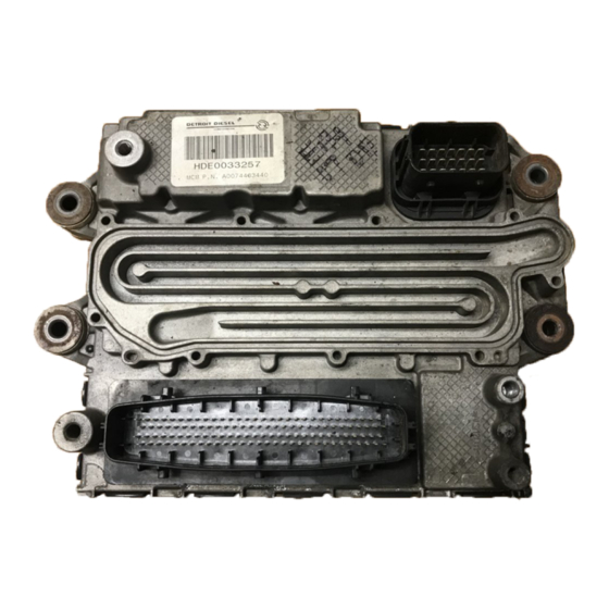
Manuals and User Guides for Detroit Diesel DDEC VI. We have
1
Detroit Diesel DDEC VI manual available for free PDF download: Application And Installation
Detroit Diesel DDEC VI Application And Installation (482 pages)
Brand:
Detroit Diesel
| Category:
Engine
| Size: 4 MB
Table of Contents
Table of Contents
7
Table of Contents
13
List of Figures
21
Table 3-13 21-Pin Connector to the MCM
24
Table 3-14 21-Pin Connector to the MCM Part Numbers
24
Table 3-23 Connector #1, 18-Pin Connector, B Key
24
Table 3-27 Connector #3, 21-Pin Connector, Key a
24
Table 3-31 Connector #1, 18-Pin Connector, B Key
24
Table 3-35 Connector #3, 21-Pin Connector, Key a
24
Table 3-37 Connector #4, 18-Pin Connector, Key C
24
Table 3-39 Connector #1, 18-Pin Connector, B Key
24
1 Introduction
31
2 Safety Precautions
33
Stands
33
Glasses
33
Welding
34
Work Place
34
Clothing
35
Electric Tools
35
Air
36
Diagnostic Tools
36
Fluids and Pressure
36
Batteries
37
Fire
38
Paint
38
Fluoroelastomer
38
Table 2-1 the Correct Type of Fire Extinguisher
38
3 Hardware and Wiring
39
Motor Control Module
41
Engine Harness
41
Figure 3-1 Motor Control Module
41
MCM 120-Pin Connector for Series 60 Engines
42
Table 3-1 MCM Connector - Series 60 (1 of 4)
42
Table 3-2 MCM Connector - Series 60 (2 of 4)
43
Table 3-3 MCM Connector - Series 60 (3 of 4)
44
Table 3-4 MCM Connector - Series 60 (4 of 4)
45
MCM 120-Pin Connector for Mbe 900 Engines
46
Table 3-5 MCM Connector - MBE 900 (1 of 4) - C Sample
46
Table 3-6 MCM Connector - MBE 900 (2 of 4) - C Sample
47
Table 3-7 MCM Connector - MBE 900 (3 of 4) - C Sample
48
Table 3-8 MCM Connector - MBE 900 (4 of 4) - C Sample
49
MCM 120-Pin Connector for Mbe 4000 Engines
50
Table 3-9 MCM Connector - MBE 4000 (1 of 4) - C Sample
50
Table 3-10 MCM Connector - MBE 4000 (2 of 4) - C Sample
51
Table 3-11 MCM Connector - MBE 4000 (3 of 4) - C Sample
52
Table 3-12 MCM Connector - MBE 4000 (4 of 4) - C Sample
53
Connector Brackets
54
Figure 3-2 Series 60 Engine 120-Pin Connector and 21-Pin Connector Tie-Wrapped to
54
MCM 21-Pin and 31-Pin Connectors
55
Table 3-15 31-Pin MCM Pigtail Connector Part Numbers
56
Table 3-16 31-Pin MCM Pigtail Connector
57
Dpf Harness
58
Figure 3-3 Aftertreatment Device
58
Figure 3-4 Typical Mounting Views of an Aftertreatment Device
59
Dpf Harness - Vertical Mount Atd (31-Pin to 10 Pin Connector)
60
Figure 3-5 Vertical and under Step Mount ATD Wiring - OEM Responsibility
60
Table 3-17 DPF 10-Pin Connector
61
Table 3-18 DDC Part Numbers for the DPF 10-Pin Connector
61
Dpf Harness - Horizontal Mount Atd (31-Pin to 10-Pin Connector/2-Pin Connector)
62
Figure 3-6 Horizontal Mount ATD Wiring - OEM Responsibility
62
Table 3-19 DPF 10-Pin Connector and 2-Pin Connector - Horizontal Mount ATD
63
Table 3-20 DDC Part Numbers for the DPF 10-Pin and 2-Pin Connector - Horizontal
63
Common Powertrain Controller
65
Figure 3-7 the Common Powertrain Controller
65
Figure 3-8 CPC Dimensions
66
Environmental Conditions
67
Figure 3-9 NAFTA Architecture On-Highway
67
Temperature
67
Water Intrusion
67
Cpc Vehicle Interface Harness
68
Figure 3-10 Vehicle Interface Harness
68
Frequency Input
69
Table 3-21 Variable Reluctance Signal Interface
69
Digital Inputs
70
Digital Outputs
70
Truck Applications
72
Vih Wiring
72
Table 3-24 Connector #2 Pin Assignments - Truck Application
73
Table 3-25 Connector #2, 18-Pin Connector, a Key
73
Table 3-28 Connector #4 Pin Assignments - Truck Application
75
Table 3-29 Connector #4, 18-Pin Connector, Key C
75
Vocational Applications
76
Table 3-32 Connector #2 Pin Assignments - Vocational Applications
77
Table 3-33 Connector #2, 18-Pin Connector, a Key
77
Coach Applications
80
Table 3-40 Connector #2 Pin Assignments - Coach Application
81
Table 3-41 Connector #2, 18-Pin Connector, a Key
81
Fire Truck Applications
84
Crane Applications
88
Transit Bus Applications
92
Vih to MCM Connector Wiring
96
Figure 3-11 Power Wiring
99
Vih Power Wiring
99
Communications - Sae J1939 Data Link
101
Wire Resistances
101
Communications - Proprietary Engine-Can Data Link
103
Power Supply - 12 Volt System
103
Average Current Draw
104
Battery Isolator
104
Main Power Shutdown
105
Fuses
106
Connectors
108
Data Link Connector
110
Wires and Wiring
111
General Requirements
111
General Wire
111
Crimp Tools
112
Deutsch Terminal Installation and Removal
112
Deutsch Terminal Installation Guidelines
112
Figure 3-14 Setting Wire Gage Selector and Positioning the Contact
113
Figure 3-15 Pushing Contact into Grommet
113
Deutsch Terminal Removal
114
Figure 3-16 Locking Terminal into Connector
114
Figure 3-17 Removal Tool Position
115
Figure 3-18 Removal Tool Insertion
115
Clipped and Soldered Splicing Method
116
Splicing Guidelines
116
Figure 3-19 Positioning the Leads
117
Figure 3-20 Securing the Leads with a Clip
117
Splicing and Repairing Straight Leads-Alternate Method 1
118
Figure 3-22 Splicing Straight Leads - Alternate Method
120
Splicing and Repairing Straight Leads - Alternate Method 2
121
Figure 3-23 Splicing Straight Leads - Alternate Method
122
Shrink Wrap
123
Figure 3-24 the Correct and Incorrect Method of Staggering Multiple Splices
124
Staggering Wire Splices
124
Conduit and Loom
125
Tape and Taping
127
Sensors
129
Factory-Installed Sensors
130
Figure 3-25 Sensor Location for the DOC and DPF
131
Oem-Installed Sensors
132
Ambient Air Temperature Sensor
133
Figure 3-26 Ambient Air Temperatures Sensor Dimensions
133
Ambient Air Temperature Sensor Installation
134
Engine Coolant Level Sensor
135
Figure 3-28 Engine Coolant Level Sensor Specifications
135
Figure 3-29 Engine Coolant Level Sensor Installation for CPC
136
Figure 3-30 Engine Coolant Level Sensor Location - Top of Radiator Tank
137
Figure 3-31 Turbo Compressor in Temperature Sensor
139
Turbo Compressor in Temperature Sensor
139
Figure 3-32 Turbo Compressor in Temperature Sensor Installation
140
Vehicle Speed Sensor
140
Figure 3-33 Vehicle Speed Sensor
141
Magnetic Pickup
141
Figure 3-34 Magnetic Vehicle Speed Sensor Installation - CPC
142
Sae J1939 Data Link
143
Vss Anti-Tamper
143
Lamps
145
Amber Warning Lamp
145
Amber Warning Lamp Requirements and Guidelines
145
Awl and Passmart
145
Figure 3-35 Amber Warning Lamp Wiring
146
Red Stop Lamp
146
Wiring Requirements
146
Figure 3-36 Red Stop Lamp Wiring
147
Red Stop Lamp Requirements and Guidelines
147
Red Stop Lamp Wiring
147
Dpf Regeneration Lamp
148
Dpf Regeneration Lamp Requirements and Guidelines
148
Programming Requirements and Flexibility
148
High Exhaust System Temperature Lamp
149
High Exhaust System Temperature Lamp Requirements and Guidelines
149
Programming Requirements and Flexibility
149
Malfunction Indicator Lamp
150
Malfunction Indicator Lamp Requirements and Guidelines
150
Low Oil Pressure Lamp
151
Requirements and Guidelines
151
Programming Requirements and Flexibility
151
Cruise Active Lamp
152
Cruise Active Lamp Requirements and Guidelines
152
Programming Requirements and Flexibility
152
Deceleration Lamp
153
Deceleration Lamp Requirements and Guidelines
153
Programming Requirements and Flexibility
153
Low Battery Voltage Lamp
154
Low Battery Voltage Lamp Requirements and Guidelines
154
Programming Requirements and Flexibility
154
Low Coolant Level Lamp
155
Low Coolant Level Lamp Requirements and Guidelines
155
Programming Requirements and Flexibility
155
Optimized Idle Active Lamp
156
Optimized Idle Active Lamp Requirements and Guidelines
156
Programming Requirements and Flexibility
156
Wait to Start Lamp
157
Wait to Start Lamp Requirements and Guidelines
157
Programming Requirements and Flexibility
157
Ags2 Backup Lamp
158
Ags2 Backup Lamp Requirements and Guidelines
158
Programming Requirements and Flexibility
158
Ags2 Check Trans Lamp
159
Ags2 Check Trans Lamp Requirements and Guidelines
159
Programming Requirements and Flexibility
159
Ags2 Trans Temp Lamp
160
Ags2 Trans Temp Lamp Requirements and Guidelines
160
Programming Requirements and Flexibility
160
4 Inputs and Outputs
162
Inputs
163
Air Condition Status
164
Installation
164
Programming Requirements and Flexibility
164
Abs Active
165
Installation
165
Programming Requirements and Flexibility
165
Auxiliary Shutdown #1
166
Installation
166
Programming Requirements and Flexibility
166
Clutch Switch
167
Installation
167
Programming Requirements and Flexibility
167
Installation
168
Programming Requirements and Flexibility
168
Cruise Control Resume/Accel Switch and Set/Coast Switch
169
Diagnostics
169
Installation
169
Programming Requirements and Flexibility
169
Diagnostic Request Switch
170
Installation
170
Programming Requirements and Flexibility
170
Dual-Speed Axle Switch
171
Installation
171
Programming Requirements and Flexibility
171
Engine Brake Disable
172
Installation
172
Programming Requirements and Flexibility
172
Engine Brake Low & Medium
173
Installation
173
Programming Requirements and Flexibility
173
Fan Override
173
Fast Engine Heat up Switch
174
Installation
174
Programming Requirements and Flexibility
174
Idle Validation 1 & Idle Validation 2
175
Installation
175
Limiters for Torque, Engine Speed, and Vehicle Speed
175
Programming Requirements and Flexibility
175
Optimized Idle Hood Tilt Switch
176
Installation
176
Programming Requirements and Flexibility
176
Optimized Idle Thermostat
177
Installation
177
Programming Requirements and Flexibility
177
Installation
178
Programming Requirements & Flexibility
178
Regen Switch
179
Installation
179
Programming Requirements and Flexibility
179
Cruise Control
187
5 Features
213
Acceleration Limiter
215
Operation
217
Cold Start - Mbe900 and Mbe4000
217
Figure 5-1 Grid Heater - MBE4000
218
Figure 5-2 Grid Heater - MBE900
219
Figure 5-3 Grid Heater - Heavy-Duty Engine
219
Cruise Control
221
Engine Brakes in Cruise Control (Optional)
222
Adaptive Cruise (Optional)
222
Cruise Auto Resume (Optional)
222
Cruise Enable
222
Set / Coast
222
Clutch Released (Manual Transmissions)
223
Installation
223
Resume / Accel
223
Service Brake Released (Automatic and Manual Transmissions)
223
Figure 5-4 Cruise Control Circuit
224
Programming Requirements and Flexibility
225
Interaction with Other Features
226
Diagnostics
227
Operation
227
Figure 5-5 Flashing Fault Codes
229
Flashing Fault Codes with Awl / Sel
229
Programming Requirements & Flexibility
231
Dual Speed Axle
231
Installation
231
Operation
231
Programming Flexibility & Requirements
231
Engine Brake Controls - Mbe900 and Mbe4000
233
Operation
233
Cruise Control or Road Speed Limit with Engine Brake
234
Engine Brake Active
234
Service Brake Control of Engine Brakes
234
Engine Brake Controls - Series
249
Engine Protection
257
Engine Starter Control
261
Ether Starting - Series
263
Fan Control
265
Fleet Management
289
Fuel Economy Incentive
297
Idle Adjust
299
Idle Shutdown Timer and Pto Shutdown
301
Limiters
309
Optimized Idle
317
Parked Regeneration
325
Passmart
329
Passwords
333
Progressive Shift
335
Starter Lockout
341
Advertisement
Advertisement
Related Products
Detroit Diesel DDFP-03DN
Detroit Diesel DDFP-03DT
Detroit Diesel DDFP-L3DT
Detroit Diesel DDFP-T3DT
Detroit Diesel DDFP-L6FA
Detroit Diesel DDFP-T6FA
Detroit Diesel DDFP-08FA
Detroit Diesel DDFP-12FT
Detroit Diesel DDFP-12FH
Detroit Diesel DD13
Detroit Diesel Categories
Engine
Industrial Equipment
Switch
Portable Generator
Controller
More Detroit Diesel Manuals
Login
Sign In
OR
Sign in with Facebook
Sign in with Google
Upload manual
Upload from disk
Upload from URL