Table of Contents
Advertisement
Quick Links
Advertisement
Table of Contents

Subscribe to Our Youtube Channel
Related Manuals for Daikin EWAP 800-C18AJYNN


Summary of Contents for Daikin EWAP 800-C18AJYNN
- Page 1 D - KIMAC00512-09EN - 1/40...
- Page 2 This Manual is a technical aid and does not represent a binding offer for Daikin. Daikin has drawn up this Manual to the best of its knowledge. The content cannot be held as explicitly or implicitly guaranteed as complete, precise or reliable.
- Page 3 ATTENTION The machines described in this manual represent a valuable investment. Maximum care should be taken to ensure correct installation and to maintain them in good running order. Installation and maintenance must be performed by qualified and specifically trained personnel only. Correct maintenance of the unit is indispensable for its safety and reliability.
-
Page 4: General Description
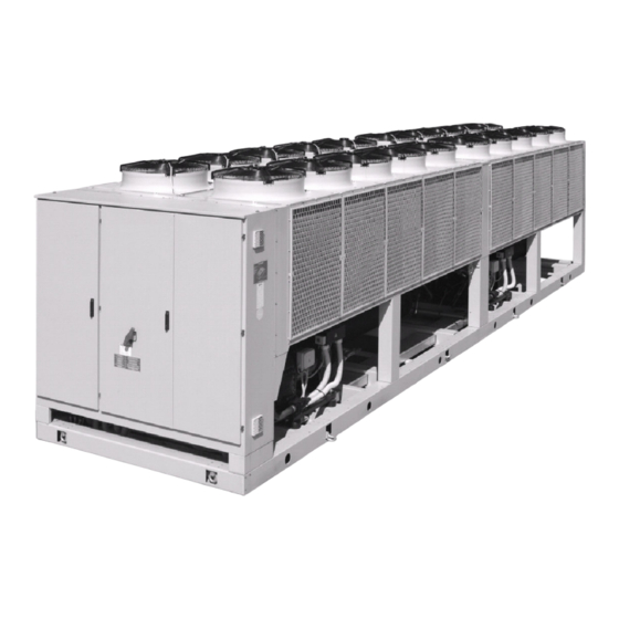
Introduction General description Each unit is completely assembled, wired, evacuated, charged, tested, ready for installation. The main components are air-cooled condensers with integral sub-cooler sections, accessible semi-hermetic single-screw compressors, shell-and-tube evaporators, shell-and-tube water heat recovery condensers (optional), oil separators, complete refrigerant piping and electrical panel (including control and power sections). Liquid line components are shut-off valves, charging valves, filter-dryers, sight-glass/moisture indicators, electronic expansion valves, liquid receivers (only with total heat recovery option). -
Page 5: Installation
DAIKIN’s responsibility. Responsibilities DAIKIN declines all present and future responsibilities referred to injuries to people and damages to things and to the unit, coming from operators negligence, the un-respected installation/maintenance data carried in this manual, the lacking of the current regulations respect referred to the safety of both the equipment and the qualified personnel in charge for the installation and the maintenance. -
Page 6: Handling And Lifting
For transport in containers, the optional container kit is available on request, for preventing damage and to facilitate the sliding of the chiller into the container during push-in and pull-out operations. The kit includes: base frame bracing plus two lifting rings fixed on it; wood planks fixed below the unit base frame. -
Page 7: Space Requirements
Suggested lifting arrangement for units with 2 compressors Use spreader bars to avoid damage to the unit Location Suggested lifting arrangement for units with 3 compressors These units are produced for outside installation on roof floors or below ground level on condition that the area is free from obstacles for condenser air flow. -
Page 8: Water Piping
When two or more units are positioned side by side it is recommended that the condenser coils of each unit are at least at 3600 mm distance (picture 6). For different installation solutions, consult DAIKIN technicians. Picture 3 Picture 4... - Page 9 A strainer should be placed in the supply water line just prior to the inlet of the evaporator and heat recovery condensers. This will aid in preventing foreign material from entering and decreasing the performance of the heat exchangers. The shell-and-tube evaporator has a thermostat and electric heater to prevent freeze-up down to -28°C. Any water piping to the unit must be protected to prevent freezing.
-
Page 10: Flow Switch
“Heat recovery mode”. It prevents against the unit shut-down for high condensing pressure. A flow switch is available from DAIKIN and it is a "paddle" type switch and adaptable to any pipe size from 5" (127mm) to 8" (203mm) nominal. - Page 11 Physical data EWAP-AJYNN R-407C Unit size Cooling capacity (1) 790,4 875,0 943,6 1026,1 1091,9 1158,0 Power input (1) 317,0 348,2 376,9 412,4 444,8 471,2 2,49 2,51 2,50 2,49 2,45 2,46 Single screw compressors N° Refrigerant circuits N° Refrigerant charge Oil charge 12,5 12,5 12,5...
- Page 12 Electrical data EWAD-AJYNN R-407C Unit size Standard voltage (1) 400 V – 3f – 50 Hz Nominal unit current (2) Max compressor current (3) Fans current Max unit current (3) Max unit inrush current (4) 1050 1054 1116 1120 1165 1265 1002 Max unit current for wires sizing (5)
- Page 13 Physical data EWAP-AJYNN with option OPRN/OPLN R-407C Unit size Cooling capacity (1) 743,7 822,1 887,1 963,2 1025,0 1091,9 Power input (1) 351,8 385,1 415,6 455,2 491,5 523,0 2,11 2,13 2,13 2,12 2,09 2,09 Single screw compressors N° Refrigerant circuits N° Refrigerant charge Oil charge 12,5...
- Page 14 Electrical data EWAP-AJYNN with option OPRN/OPLN R-407C Unit size Standard voltage (1) 400 V – 3f – 50 Hz Nominal unit current (2) Max compressor current (3) Fans current Max unit current (3) Max unit inrush current (4) 1048 1050 1104 1106 1154...
- Page 15 Physical data EWAP-AJYNN/A R-407C Unit size Cooling capacity (1) 854,1 954,2 1027,8 1123,9 1195,7 1252,7 Power input (1) 288,2 321,1 350,7 386,3 418,4 428,8 2,96 2,97 2,93 2,91 2,86 2,92 Single screw compressors N° Refrigerant circuits N° Refrigerant charge Oil charge 12,5 12,5 12,5...
- Page 16 Electrical data EWAP-AJYNN/A R-407C Unit size Standard voltage (1) 400 V – 3f – 50 Hz Nominal unit current (2) Max compressor current (3) Fans current Max unit current (3) Max unit inrush current (4) 1051 1055 1125 1129 1172 1259 1026 Max unit current for wires sizing (5)
- Page 17 Physical data EWAP-AJYNN/A with option OPRN/OPLN R-407C Unit size Cooling capacity (1) 818,2 911,3 981,1 1069,8 1137,3 1202,1 Power input (1) 311,5 346,9 378,6 418,0 453,6 463,4 2,63 2,63 2,59 2,56 2,51 2,59 Single screw compressors N° Refrigerant circuits N° Refrigerant charge Oil charge 12,5...
- Page 18 Electrical data EWAP-AJYNN/A with option OPRN/OPLN R-407C Unit size Standard voltage (1) 400 V – 3f – 50 Hz Nominal unit current (2) Max compressor current (3) Fans current Max unit current (3) Max unit inrush current (4) 1036 1038 1097 1100 1145...
- Page 19 Sound pressure levels EWAP-AJYNN and /A Sound pressure level at 1 m from the unit in free field (rif. 2 x 10 Standard unit size unit size 63 Hz 125 Hz 250 Hz 500 Hz 1000 Hz 2000 Hz 4000 Hz 8000 Hz 78,5 79,0 80,5...
-
Page 20: Relief Valves
Relief Valves As a safety precaution and to meet code requirements, each chiller is equipped with pressure relief valves located on the coil condenser, evaporator, heat recovery condenser (if supplied) and liquid receiver for the purpose of relieving excessive refrigerant pressure (caused by equipment malfunctioning, fire etc.) to the atmosphere. -
Page 21: Evaporator Pressure Drop
Evaporator Pressure Drop EWAP-AJYNN EWAP-AJYNN/A C16 – C17 – C18 – C16/A – C17/A – C18/A C13 – C14 – C15 – C13/A – C14/A – C15/A C12/A C10/A – C11/A – 900/A – 950/A C10/A – C11/A 900 – 950 – 850/A Flow rate (l/s) Flow rate (l/s) D - KIMAC00512-09EN - 21/40... - Page 22 Partial Heat Recovery Exchanger (Plate Exchanger) Pressure Drop Flow rate (l/s) D - KIMAC00512-09EN - 22/40...
- Page 23 Total Heat Recovery Exchanger Pressure Drop EWAP-AJYNN EWAP-AJYNN/A Flow rate (l/s) Flow rate (l/s) D - KIMAC00512-09EN - 23/40...
-
Page 24: Prestart System Checklist
Thermometers wells, thermometers, gauges, control wells, controls, etc., installed Minimum system load of 60% of machine capacity available for testing and adjusting controls Note: This check list must be completed and sent to the local DAIKIN service location two weeks prior to start-up. Operation Operator Responsibilities It is important that the operator become familiar with the equipment and the system before attempting to operate the chiller. - Page 25 The liquid refrigerant before leaving the condensing section is passing inside the sub-cooler where is cooled below the saturation temperature, to compensate the pressure drops through the liquid line and to increasing the evaporator capacity. After the sub-cooler the liquid refrigerant enters in the liquid receiver, where the exceeding charge is accumulated during the “cooling mode”...
- Page 26 A display illustrates the machine's operating status, programmable values and set points e.g. temperatures, and pressures of fluids (water, refrigerant). Device controls maximize the DAIKIN chillers energy efficiency and reliability characteristics. It uses sophisticated software with predictive logic to select the most energy efficient combination of compressor, electronic expansion valve and condenser fan to keep stable operating conditions and maximize energy efficiency.
-
Page 27: System Security
System security Phase monitor Freeze protection An evaporator’s flow controller input (stops the unit) Remote on/off input. Regulation type Proportional + integral + derivative regulation on the input probe of the evaporator water leaving temperature. Condensation The condensation can be carried out according to temperature or pressure. The fans can be managed according to ON/OFF mode or with a 0/10 V modulating signal. - Page 28 Heat Recovery Microprocessor Control All the units equipped with the heat recovery water condensers have an additional “microprocessor control” to manage the heat recovery function of the unit . The microprocessor is installed inside the main control box below the controller key pad.(see the picture below) HEAT RECOVERY OPERATION Key Pad...
- Page 29 the request of cooling load and the capacity is depending from the number of the compressors running and the unloading position of them. To run the unit in heat recovery mode follow the items listed below: 1) Verify the installation of the water flow switch done by the installer and check the electrical connection at M3.426 and M3.427 terminal blocks inside the electrical panel 2) Verify the installation of the microprocessor sensor in the pocket well of the water return common header (done by the installer)
- Page 30 Heat Recovery Microprocessor Set-up The unit supplied with the heat recovery condensers is equipped with an additional microprocessor (TC10 see electrical wiring diagram) with two, three or four steps to control the hot water temperature, according to the number of the heat exchangers installed on the unit(one step for each compressor). For reference how to set this microprocessor see the Specific manual supplied with the unit.
-
Page 31: System Maintenance
System Maintenance General To ensure proper operation at peak capacity and to avoid damage to package components, a program of periodic inspections should be set up and followed. The following items are intended as a guide and are to be used during inspection and must be combined with sound coming from compressor and electrical practices to ensure trouble- free performance. - Page 32 No maintenance is ordinary required except the occasional removal of dirt and debris from the outside surface of the fins. DAIKIN recommends the use of foaming coil cleaners available at air conditioning supply outlets. Use caution when selecting such cleaners as some may contain potentially harmful chemical. Care should be taken not to damage the fins during cleaning.
- Page 33 To reduce the oil circulation in the refrigerant circuit, the oil separator is installed on the compressor discharge line Lubricating oil approved by DAIKIN is mentioned on the compressor label. The oil pressure transducer monitors the oil injection pressure on the compressor. If the oil pressure value is below the setting point inside the microprocessor control the compressor stops.
- Page 34 3. The charge can be added at any load condition. Charging the refrigerant 1. Connect the refrigerant bottle with a filling pipe to the filling valve on the evaporator head. Before firmly tightening the refrigerant bottle valve, open it and force the air out from the filling pipe. Tighten the charging valve connection and fill the refrigerant.
- Page 35 Preventive maintenance schedule SCHEDULE Operation TYPE OF OPERATION Six- Ref. No. Weekly Monthly Yearly Monthly Reading and recording of suction pressure Reading and recording of discharge pressure Reading and recording of supply voltage Reading and recording of current intensity Check refrigerant charge and possible moisture in the circuit refrigerant through the liquid sight glass Check the suction temperature and the superheating Check setting and operation of safety devices...
-
Page 36: Maintenance Shut-Down
The order should include part name, part number, model number and serial number of the unit involved. After DAIKIN inspection of the returned part, if the failure is due to faulty material or workmanship, credit will be issued on the customer's purchase order. All defective parts shall be returned to DAIKIN factory, transportation charges prepaid. -
Page 37: Troubleshooting Chart
Check motor and Replace if defective. Blown High discharge pressure. See Corrective steps for high discharge pressure. Compressor Compressor internal problem. Contact DAIKIN. noisy or Oil injection not adequate. Contact DAIKIN. vibrating Compressor will Defective capacity control. See capacity control section. - Page 38 Troubleshooting chart PROBLEM POSSIBLE CAUSES POSSIBLE CORRECTIVE STEPS Discharge shutoff valve partially closed. Open shutoff valve. Non condensable in the system. Purge the non condensable from the condenser coil after shutdown. Fans not running. Check fan fuses and electrical circuits. Fan control out of adjustment.
- Page 39 Periodic obligatory checks and starting up of appliances under pressure The units are included in category IV of the classification according to European Directive PED 97/23/EC. For chillers belonging to this category, some local regulations require a periodic inspection by an authorized agency. Please check with your local requirements.
- Page 40 EWAP 850-C18AJYNN/A Daikin units comply with the European regulations that guarantee the safety of the product. Daikin Europe N.V. is participating in the EUROVENT Certification Programme. Products are as listed in the EUROVENT Directory of Certified Products. DAIKIN EUROPE N.V.
Need help?
Do you have a question about the EWAP 800-C18AJYNN and is the answer not in the manual?
Questions and answers