
Related Manuals for Dalla Corte STUDIO


Summary of Contents for Dalla Corte STUDIO
- Page 1 - user manual benutzerhandbuch - manual de usuario notice pour l’utilisateur...
-
Page 2: Table Of Contents
User manual 1 General safety warnings 2 Preparations for installation 3 Set up and use of the appliance 4 Espresso coffee brewing 5 Preparation of hot milk 6 Periodic maintenance performed by the user 7 Display 8 Menu 9 Alarms Wiring diagram | 45... - Page 3 Connections - Idric connection version Fig.1a LEGEND 1 Water tap 2 Flexible water hoses 3 Water softener (optional) 4 Drain hose 5 Drain siphon 6 Electric supply cable 7 Single phase electric SCHUKO plug 16A A Hole on support panel B Under-counter space 46 |...
- Page 4 Connections - Tank version Fig.1b LEGEND 6 Electric supply cable 7 Single phase electric SCHUKO plug 16A | 47...
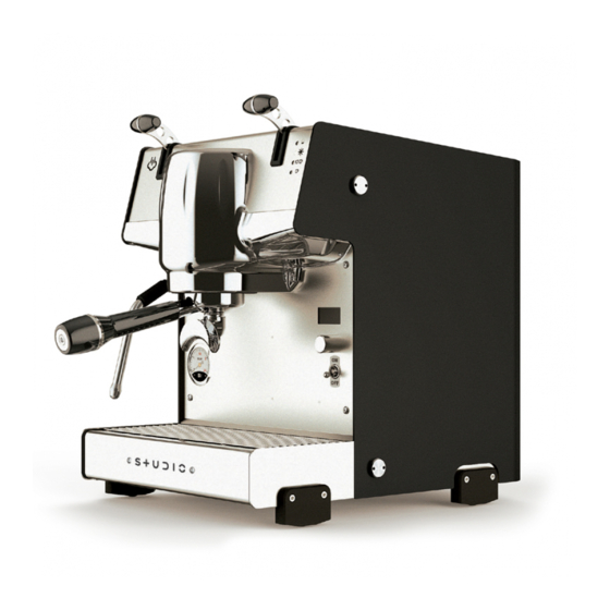
- Page 5 Machine description Fig.2 LEGEND 1 Main switch 2 Feet 3 Basin 4 Steam wand 5 Steam lever 6 Selector lever 7 Steam boiler pressure gauge 8 Selector knob 9 Group head 10 Portafilter 11 Display 12 Tank panel Fig.3 LEGEND L1 Line L2 Manual erogation L3 Double shot erogation...
-
Page 6: General Safety Warnings
The manufacturer reserves the right to modify this manual without the obli- gation to update previous editions. The pictures in this manual are entirely indicative. Dalla Corte reserves the right to make changes with regard to the production and the manual without the obligation to update production and previous manuals. - Page 7 (For proper disposal follow the instructions for the separate collection of waste in your country). The manufacturer cannot be held liable for any damage caused by the lack of the appliance’s grounding system. In order to ensure the electrical safety of this appliance it is mandatory to set up the grounding system by contacting a licensed electrician who must check that the electrical capacity of the system is suitable for the maximum power of the appliance specified on the plate.
- Page 8 The appliance is not intended for use by children, persons with reduced physical, sensory and mental capabilities or lack of knowledge, unless su- pervised and instructed. The maximum and minimum storage temperatures must be within the range 0°C, + 55°C. The operating temperature must be within the range + 5°C, + 30°C.
- Page 9 • Do not leave the cable hanging on the edges of the table top; make sure the cable does not touch hot surfaces. • The device is not designed to work with external timers or remote control systems. • Before filling the jug switch off the appliance and disconnect the plug from the mains.
- Page 10 • To guarantee the efficiency of the appliance and its correct operation it is essential to follow the manufacturer’s instructions by carrying out routine maintenance. • Never remove the filter holder during the coffee brewing operation. • Do not use water jets for cleaning operations and do not immerse the appliance in water.
- Page 11 WARNING: ELECTRIC SHOCK HAZARD • Insert the plug into a compliant grounded socket. • Do not tamper with grounding. • Do not use an adapter. • Do not use an extension cord. • Before filling the jug switch off the appliance and disconnect the plug from the mains.
- Page 12 Area of use and intended use The espresso coffee machine is designed for: the preparation of espresso coffee through the appropriate dispensers, the heating of the milk to prepa- re cappuccino by supplying steam from the special nozzle according to the procedures described below.
-
Page 13: Preparations For Installation
Do not perform this operation alone. We recommend the appliance to be handled by two persons. The manufacturer cannot be held liable for damage caused by improper handling or failure to comply with the aforementioned rules. 2. Preparations for installation The appliance must be placed on a surface that can guarantee a safe support of the equipment. - Page 14 The maximum dimensions 312 x 390 x 419,2 and weight 28. Water tank volume 4 lt. Data plate serial n Fxxxxxxxx YEAR xxxx STUDIO MODEL DALLA CORTE S.R.L. Coffee circuit Boiler 3l VIA ZAMBELETTI, 10 20021 BARANZATE (ITALY) pressure 1.1 MPa 0.15MPa MADE IN ITALY Maximum water pressure 0.6MPa...
- Page 15 Machine accessories • single-dose complete portafilter • double-dose complete portafilter • two single-dose filters with two different depths • two double-dose filters with two different depths • one shower • blind filter • cleaning brush • box of cleaning tablets •...
-
Page 16: Set Up And Use Of The Appliance
3. Set up and use of the appliance NOTE Before switching on (the machine must be disconnected from the power grid) clean the external surfaces of the machine, wash the grids, filters, filter holders, steam nozzles with dishwashing detergent and rinse thoroughly. Carry out the following instructions by consulting the diagram shown in fig.2, fig.1b for the JUG version and fig.1a for the WATER SUPPLY version. - Page 17 • The value shown on the display will stop flashing at the end of the boiler heating phase. The machine is then ready for use. NOTE Carry out a unit washing cycle as explained in paragraph 6 when the ma- chine is ready for use and BEFORE using it.
-
Page 18: Espresso Coffee Brewing
7. Dry the jug. 8. Carefully reinsert the jug into the appropriate compartment of the espresso machine making sure not to spill the water inside the machine. 9. Reinsert the silicone tube into the appropriate hole of the jug. 10. Reposition the panel 12 fig.2. 3.2 Water to use It is recommended to use bottled mineral water with a low content of mineral salts to prevent scale formations in the jug and in the hydraulic circuit of the... -
Page 19: Preparation Of Hot Milk
• Press the coffee firmly with the special manual press supplied. • Clean the edge of the filter from any coffee residues and hook the filter holder to the brew unit. • Place selettore S (8 fig.2) in the desired position, L1 for single coffee and L2 for double coffee. - Page 20 NOTE To obtain good quality milk cream it is necessary to perform a specific proce- dure during heating. This procedure can be taught through training courses and specific videos. The procedure is not described in this manual for safety reasons. WARNING: BURN HAZARD Use the special insulating handle to maneuver the steam nozzle.
-
Page 21: Periodic Maintenance Performed By The User
6. Periodic maintenance performed by the user WARNING The manufacturer cannot be held liable for damage to people, things or animals caused by improper maintenance. The efficiency of the equipment is guaranteed by proper maintenance; it is therefore important to follow the instructions below in order to perform proper maintenance. - Page 22 Daily cleaning of parts in contact with coffee Unhook the filter holder (10 fig.2) from the brew unit (9 fig.2) every evening or at the end of the use of the appliance, and wait for it to cool down or cool it under running water.
- Page 23 Boiler washing (annual) It is necessary to completely empty the water in the boiler on an annual basis. This operation must be carried out exclusively by a specialized technician and it is therefore necessary to contact the manufacturer or an authorized technical support center.
-
Page 24: Display
7. Display The following screen is shown on the Shows the time taken to brew the display of the machine during nor- coffee. (remains displayed until the mal operation. next brewing). It shows in real time the water flow for brewing. The display shows the following screen if the timer function is enabled and the value is outside the set working time. -
Page 25: Menu
8. Menu You can access the MENU by pres- BOILER ENABLING sing the selector knob for 3 seconds in order to view useful information or adjust the parameters of the espres- so machine. Turn the selector knob to scroll through the MENU items and press This menu item allows you to enable it to access the submenu. - Page 26 The value will start flashing by pres- Press the selector knob to access sing the selector knob; you can adjust the menu. the value by turning the knob. Press the selector knob again to confirm. The boiler will be enabled by se- lecting ON, and will be disabled by selecting OFF.
- Page 27 Press the selector knob for 3 seconds to return to the previous menu. UNIT TEMPERATURE This menu item allows you to adjust Press the selector knob to access the the temperature of the unit. menu. Press the selector knob to access the menu.
- Page 28 Press the selector knob for 3 seconds Here you can choose whether you to return to the previous menu. want to adjust the single or the dou- ble dose. DOSES ADJUSTMENT Choose by turning the selector knob This menu item allows you to adjust and confirm by pressing it.
- Page 29 At this point a screen is displayed during the brewing showing the de- livery parameters such as tempera- ture, stopwatch and flow. When the espresso reaches the desi- red level, stop brewing by placing the Press the selector knob to access the selector to the rest position.
- Page 30 LIGHT ENABLING The value will start flashing by pres- This menu item allows you to enable sing the selector knob; you can adjust or disable the front light of the espres- the value by turning the knob. Press so machine. the selector knob again to confirm.
- Page 31 SERIAL NUMBER This menu item displays the serial number of the espresso machine. Press the selector knob to access the menu. FIRMWARE This menu item displays the firmwa- re version of the espresso machine. Then the number of coffees divi- COUNTERS ded by single and double dose is This menu item displays the number...
- Page 32 SETTINGS confirm to go to the next box. This menu allows making adjust- You are allowed to access the menu ments or changing some parameters if the password is correct. of the espresso machine. Press the selector knob to access LANGUAGE the menu.
- Page 33 the value by turning the knob. Press RESET the selector knob again to confirm. This submenu allows you to reset the Press the selector knob for 3 seconds counters and the alarm history. to return to the previous menu. Press the selector knob to access the menu.
- Page 34 Press the selector knob to confirm the selection. Press the selector knob for 3 seconds to return to the previous menu. COUNTERS Press the selector knob for 3 seconds This menu item allows you to reset to return to the previous menu. the brewing counters.
- Page 35 BOILER TEMPERATURE DISPLAY This menu item displays the actual temperature read by the temperatu- re probe of the steam boiler. The value will start flashing by pres- sing the selector knob; you can adjust the value by turning the knob. Press the selector knob again to confirm.
- Page 36 WATER SUPPLY TIMER This menu item allows you to set This menu item allows enabling/di- whether the espresso machine will sabling and programming the timer be supplied using the water coming function of the espresso machine. from the jug or by connecting it to the water supply.
- Page 37 Press the selector button in case you The value will start flashing by pres- still want to use the machine even if sing the selector knob; you can adjust turned off by the timer. At this point the value by turning the knob. Press the machine will start to heat up in the selector knob again to confirm.
- Page 38 Press the selector knob to access Automatic Switch-off indicates how the menu. much time must pass after the last coffee prepared outside the set time, so that the machine will switch off again. It can be set from a minimum of 30 minutes up to a maximum of 120 minutes.
-
Page 39: Alarms
9. Alarms The ALXX screen is displayed if one of the following alarms occurs: DESCRIPTION. Alarm Cause Effect AL01 The alarm is enabled if The boiler heating and boiler loading functions Boiler the boiler temperature are inhibited; the unit with all its functions Timeout probe does not rise above continues working. - Page 40 Alarm Cause Effect AL04 The alarm is enabled if the The boiler heating and boiler loading Boiler overtem- boiler temperature probe re- functions are inhibited; the unit with perature (Boiler ads a temperature of 5° higher all its functions continues working. set + 5°C) than the set one The alarm display is canceled by...
- Page 41 Alarm Cause Effect AL07 The alarm is enabled The unit heating function is disabled; Unit temperature if the boiler temperature the boiler continues working. probe interrupted probe reads the minimum The alarm display is canceled by pres- in short circuit range and is therefore sing the encoder but the unit remains interrupted...
- Page 42 Alarm Cause Effect Boiler level alarms AL10 The alarm is enabled if the level The boiler loading and boiler heating probe is open continuously for functions are disabled. Self-level more than the time set on the The alarm is reset by pressing the enco- alarm “timeout level”...
- Page 43 Alarm Cause Effect General alarms AL13 The alarm is At this point Equadro is reset (except for the counters) Data loss enabled when and the default data is reloaded. The screen display Equadro and of the alarm is canceled by pressing the encoder button Flash do not pass the checksum AL14...
-
Page 44: Wiring Diagram 213
Schema elettrico Wiring diagram Schaltplan Esquema eléctrico Schéma électrique V200-240 Hz 50-60 | 213... - Page 45 Schema elettrico Wiring diagram Schaltplan Esquema eléctrico Schéma électrique V110-120 Hz 50-60 214 |...
- Page 46 EN 55014- 1:2006 +A1:2009+A2:201; EN 55014-2:2015; EN 61000-3-2:2014; EN 61000-3-3:2013 EN 60335-1:2012 + A11:2014; EN 60335-2- 64:2016; EN 62233:2008 Dalla Corte S.R.L. is authorized to hold the technical file. The legal representative Paolo Dalla Corte 216 | 216 |...
- Page 47 è composta l’apparecchiatura. Per informazioni contattare: DALLA CORTE S.r.l. - Via Zambeletti 10 Baranzate (MI) Tél. +39 02 45486443 220 | 220 |...
- Page 48 Materialien, aus denen die Geräte bestehen. For information contact: DALLA CORTE S.r.l. - Via Zambeletti 10 Für weitere Informationen wenden Sie sich Baranzate (MI) Tél. +39 02 45486443 bitte an: DALLA CORTE S.r.l. - Via Zambeletti 10 Baranzate (MI) Tél. +39 02 45486443 | 221...
- Page 49 Pour tout complément d’information, Para más información contactar: s’adresser à: DALLA CORTE S.r.l. - Via Zambeletti 10 DALLA CORTE S.r.l. - Via Zambeletti 10 Baranzate (MI) Tél. +39 02 45486443 Baranzate (MI) Tél. +39 02 45486443...
- Page 50 | 223...
- Page 51 Dalla Corte S.r.l. Via Zambeletti 10 20021 Baranzate (MI) Italy T +39 02 454 864 43 info@dallacorte.com www.dallacorte.com Z-0011 224 |...
Need help?
Do you have a question about the STUDIO and is the answer not in the manual?
Questions and answers