Advertisement
Index
DATA TAG
•
ACCESSORIES LIST
•
INSTALLER'S GUIDELINES
•
INSTALLATION
•
INITIAL SET UP
•
HEATING
•
GROUP DOSES PROGRAMMING
•
MACHINE OPERATION
•
MACHINE ADJUSTMENTS
•
TEST
•
ALARM ADMINISTRATION
•
The manufacturer reserves himself the right to modify the present manual without the obligation to up to
date the previous editions.
DALLA CORTE
Via Broglio, 24
20158 Milano Italy
End user must set up electrical, water and drain systems in advance, to ensure a correct installation.
Installer can not modify systems set up in advance by the end user (see chapter "End User Set Up
Procedures" in the Use and Maintenance Manual enclosed with each unit.)
INSTALLER'S INSTRUCTIONS
INSTALLER'S MANUAL
ATTENTION
DATA TAG
Serial n°
S.r.l
l.
Maximum water pressure 0.6 Mpa
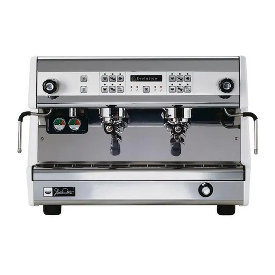
MOD. 20.03 EVOLUTION
400 V 3N ~
230 V 3 ~
230 ~
WATT.
ATTENTION
ANNO 2007
13,5
0.15 MPa
Hz 50 – 60
IPX2
RELEASE 7.03
1
Advertisement
Table of Contents

Subscribe to Our Youtube Channel
Related Manuals for Dalla Corte 20.03 EVOLUTION


Summary of Contents for Dalla Corte 20.03 EVOLUTION
- Page 1 Serial n° ANNO 2007 S.r.l Via Broglio, 24 13,5 0.15 MPa 20158 Milano Italy Maximum water pressure 0.6 Mpa MOD. 20.03 EVOLUTION 400 V 3N ~ Hz 50 – 60 230 V 3 ~ 230 ~ WATT. IPX2 ATTENTION End user must set up electrical, water and drain systems in advance, to ensure a correct installation.
-
Page 2: Accessories List
ACCESSORIES LIST Set of filter holders with spouts + 1 filterholder for two with spout Complete set of flexible hoses for connection to water system Two sets of filter baskets Set of shower screens Group brush Box of 120 cleaning tablets for group head ATTENTION This machine is to be used exclusively in the type of operation it was designed for. -
Page 3: Installation
INSTALLATION ATTENZIONE Perform installation in accordance with local laws and regulations, and follow the instructions provided below. Manufacturer can not be held responsible for damages to humans, animals or objects caused by an incorrect installation. This machine must be not installed in area where a water propulsion jet is present. Machine’s installation, using and maintenance must be made only by by qualified staff . -
Page 4: Initial Setup
Connection to electrical circuit via approved plug, which must be accessible after installation, with machine in operating mode. To connect the power cord of the machine to the circuit of the building, each lead going to the main switch of machine should be identified according to its symbol (N=Neutral, 1=Phase 1, 2=Phase 2, 3=Phase 3, grounding symbol for yellow/green lead), so as not to invert wiring and cause malfunctions. -
Page 5: Machine Operation
Immediately afterwards, boiler filling starts and Led 7 turns on; when boiler is filled up Led 7 ( L ) turns off. Verify that LED-8 (boiler heating LED) also turns on.It means the machine is heating HEATING While the boiler is heating, the coffee group heads do not operate nor heat up. However, it is possible to reserve heating of the group heads by pushing the button P7 for 10 seconds on each of the groups required for operation. -
Page 6: Machine Adjustments
MACHINE ADJUSTMENTS This espresso machine has a series of adjustable parameters to optimize its functions and coffee extraction. Only qualified personnel specifically trained by the manufacturer may perform parameter adjustments Parameter programming may be accessed through the use of the remote programmer supplied to all authorized dealers Connect the remote control to the cable inside the machine, on the right upper side The programmer will display (main menu) - Page 7 G R O U P - - N . 2 - S E T - - 9 5 , 0 ° C . - - - - The default is 95 ° Degrees C. Range is between 80° Degrees C to 110° Degrees C Push ►...
- Page 8 If YES is confirmed, the free dose button ( P 3) on each group head will operate, while by choosing NO this function is locked out and only the programmable doses buttons operate Push ► or ◄ to change this parameter and press OK to confirm After confirmation the display shows C A S H - C O N N E C T I O N...
- Page 9 Without the GCS system the display shows C O F F E E - G R O U P - N . 1 s 1 - = - - 1 5 0 - - - S1 (single short coffee ) blinks , push or ...
-
Page 10: Visual Menu
Sel 3 = single long coffee Sel 4 = double long coffee = parameter referring to Grinder 1 = parameter referring to Grinder 2 Keep pressing the OK button until the display exits the DOSES menu and displays - - T E M P E R A T U R E S - - S E T T I N G S - - - D O S E S... - Page 11 With GCS C O U N T E R - G R I N D I T E M P E R A T U R E S - COUNTERS (the default) will blink. COUNTERS Push or to select and press OK to confirm.
- Page 12 This writing is referred to the text of the display of the palmer, the 2 lines are alternating, showing the software release of the palmer and cyclically all the possible alphanumeric characters. By pressing we go to the test of the buttons of the control panel and of the buttons of the palmer. - - - - - K E Y - P 0 0 - - - - By pressing any button you see its identification on the first line(from P01 to P06 buttons of group keyboard, P07 cups-heater button, P08 and P09 hot water buttons, from P10 to P14 palmer buttons),...
- Page 13 - - - - R E L A Y - 3 - - - - - - - - - - - - O F F - - - - - - By pressing OK, OFF becomes ON and the heating elements of the boiler start working. By pressing OK again you go back to the OFF status By pressing you go to R4= solenoid valve of the boiler autolevel...
-
Page 14: Alarms Menu
By pressing you check the proper functioning of the GCS – grinder control system - - - - - G R I N D E R - - - - - - - - - - P A S S - - - - - - If you see PASS on the screen it means that the connection is OK Keeping on pressing ON for 10 seconds ,you go out of the menu “test”... -
Page 15: Parameters Range
Group 2 lockup, LED # 6 of group 2 blinks and machine emits 3 beeps. To cancel the alarm turn the main switch of the machine off and back on. This alarm is triggered when the electronic board senses that the readings of the temperature probe in group 2 are out of range. -
Page 16: Wiring Diagram
WIRING DIAGRAM INSTALLER’S INSTRUCTIONS RELEASE 7.03... - Page 17 INSTALLER’S INSTRUCTIONS RELEASE 7.03...
- Page 18 LEGEND WIRING DIAGRAM Trafo Transformer to all solenoid valves Boiler safety thermostat Boiler heater switch Rs-c Boiler heating element Pump motor Rs-st Cup warmer heating element Auto-fill relay switch R-the Hot water solenoid relay switch Group 1 solenoid relay Group 2 solenoid relay Group 3 solenoid relay Group 4 solenoid relay Pump motor relay...
- Page 19 GR 2 GR 1 Led2 Led3 Led1 Led6 Led5 Led7 Led8 Led9 Led10 Led4 INSTALLER’S INSTRUCTIONS RELEASE 7.03...
- Page 20 LEGEND Main switch Drip tray Drip tray grill Steam wand Steam valve Hot water spigot Water pressure manometer Boiler pressure manometer Dispensing group head One-cup filter holder Two-cup filter holder Adjustable foot Hot water dispensing buttons Dose button – One short coffee Dose button –...
Need help?
Do you have a question about the 20.03 EVOLUTION and is the answer not in the manual?
Questions and answers