Dalla Corte SUPER MINI Use And Maintenance Manual
Hide thumbs
Also See for SUPER MINI:
- User manual (60 pages) ,
- User manual (68 pages) ,
- User manual (76 pages)
Table of Contents
Advertisement
USE AND MAINTENANCE MANUAL
The manufacturer has the right to modify this manual without being obliged to
update the previous editions.
.
DALLA CORTE
Via Broglio, 24
20158 Milano Italy
• 1 filterholder for 1 shot
• 1 filterholder for 2 shots
• 1 filter for 1 shot
• 1 filter for 2 shots
• 1 shower
• 1 brush
• 1 manual coffee- tamper
• 1 T-shaped key
• 1 pipe for the water connection
• 1 pipe for the drainage connection
This product is to be used only for the aim for which it has been projected . Any different use is to be
considered improper and therefore unreasonable. The producer is not responsible for damage
caused to people, objects, or to the machine itself if this is used in a wrong or unreasonable way.
USER'S MANUAL
SUPER MINI
IDENTIFICATION PLATE
N.F.
S.r.l
Lt.
MOD.
VOLT.
WATT. 2850
EQUIPMENT OF THE MACHINE
3,50
SUPER-MINI
220
Hz
IPX2
WARNING
YEAR
0.15MPa
50 - 60
LII REV. 03
1
Advertisement
Table of Contents

Related Manuals for Dalla Corte SUPER MINI


Summary of Contents for Dalla Corte SUPER MINI
-
Page 1: Identification Plate
USE AND MAINTENANCE MANUAL SUPER MINI WARNING The manufacturer has the right to modify this manual without being obliged to update the previous editions. IDENTIFICATION PLATE DALLA CORTE N.F. YEAR S.r.l Via Broglio, 24 3,50 0.15MPa 20158 Milano Italy MOD. - Page 2 WARNING The installation must be done following the current regulation, according to the instructions of the manufacturer and of qualified personnel. Carefully read the instructions and the warnings contained in this manual because they give important indications about the installation of the machine and its functioning. Check that the installation systems have been prepared according to the instructions contained in this manual .
-
Page 3: Electrical Installation
Place the machine on a surface that guarantees a secure support. To get ready for set up , make sure you have an opening ( A-pic.1) on the support surface to allow connection with systems in the space below ( B-pic.1). The machine should be exclusively connected to a source of cold drinking-water. - Page 4 Install the drain flexible pipe on the connection holding the rubber of the drain basin placed under the basin and put the other end of the pipe directly into the drain siphon . Check that the drain pipe has the correct sloping to allow the basin to discharge quickly. ATTENTION If you do not follow the previous instructions, the safety and the lasting of the machine may be endangered and the warranty itself decays.
- Page 5 Put the milk in a jug with anti-burning handle. Put the steam pipe (8) into the jug and open the steam tap (5) related to the steam pipe that you are using. When the temperature of milk is the one you want, close the steam tap. When this operation finishes , clean the steam pipe with a damp cloth in order to avoid milk crustings on the pipe itself.
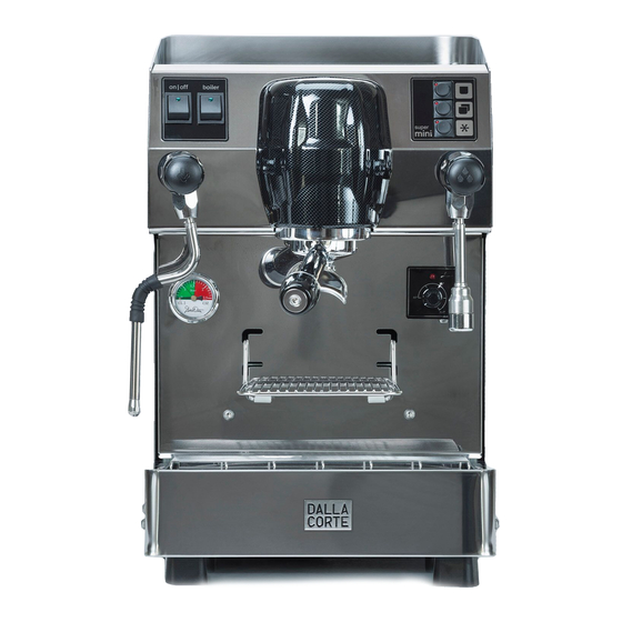
- Page 6 Fig. 2 LEGEND General switch Boiler switch Leds 3 buttons keyboard Coffee group Steam tap Hot water tap Boiler manometre Steam lance Complete filter-holder Basin grill Basin Shelf for coffee-cups Hot water supply lance Back panel Upper cup-resting panel ALARMS SYSTEM USER’S MANUAL LII REV.
- Page 7 This machine ,as well as performing the functions we have described, also checks their proper functioning. If one of this functions is not working properly, an alarm is created and it can be recognized in the following way: Slow flashing of the led when button is pressed •...
- Page 8 The coffee doses are programmed in the following way: • Keep on pressing the button P3 of the keyboard until all the three leds light up (about 30”) • Prepare the 1- dose filterholder and press the button P1( coffee supplì starts), when You get the quantity you want ,press the button P3 to stop (the led of the button P1 switches off) •...
- Page 9 GROUP RESISTANCE SECURITY THERMOSTAT EV GROUP EV BOILER LEVEL PRESSOSTAT PUMP KEYBOARD GROUP TEMP. PROBE BOILER SWITCH TERMINAL BOARD VOLUMETRIC COUNTER GENERAL BOILER LEVEL TEMPERATURE CENTRAL SWITCH PROBE REGULATION CONTROL UNIT USER’S MANUAL LII REV. 03...
Need help?
Do you have a question about the SUPER MINI and is the answer not in the manual?
Questions and answers