
Related Manuals for GEZE GC 342


Summary of Contents for GEZE GC 342
- Page 1 GC 342 safety sensor EN Installation and operating instructions 167391-03 47.0159 / V3 – 12.19...
-
Page 2: Table Of Contents
GC 342 safety sensor Contents Symbols and illustrations .................3 Revisions and validity ..................3 Product liability ....................3 Reference documents ..................4 Installation information ................4 Safety ......................4 Intended use........................4 Safety notices ........................4 Safety-conscious working ....................5 Environmentally conscious working ................6 Description ....................6 Supplied by GEZE ..................7 Installation ....................8... -
Page 3: Symbols And Illustrations
GC 342 safety sensor 12.1.6 Resetting to factory settings ..................27 12.2 Settings with the remote control ................28 Detection areas ..................31 Maintenance ...................32 Fault messages and troubleshooting ..........32 Technical data ..................36 accessories / Spare parts ..............38 Symbols and illustrations Important information and technical notes are highlighted to explain cor- rect operation. -
Page 4: Reference Documents
à Make sure that the cover of the door control is fitted correctly and earthed. à If unauthorised changes are made to the system, GEZE cannot be held liable in any way whatsoever for any resulting damage, and the approval for use in escape routes or emergency exits ceases. -
Page 5: Safety-Conscious Working
GC 342 safety sensor Safety à Only original GEZE parts may be used for repair and maintenance work. à Observe the latest versions of directives, standards and country-specific regulations, in particular: à aSR a1.7 “Doors and gates” à DIN 18650 “Building hardware – Powered pedestrian doors”... -
Page 6: Environmentally Conscious Working
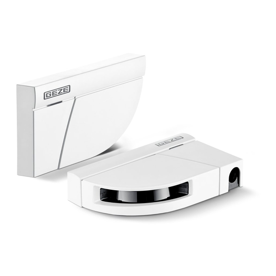
Description GC 342 safety sensor Environmentally conscious working When disposing of the door system, separate the different materials and have them recycled. Description The GC 342 is a safety sensor based on laser technology for automatic swing doors. To safeguard the rotating door leaf and the finger protection area, one module each must be installed in the top corner on both sides of the door leaf. -
Page 7: Supplied By Geze
GC 342 safety sensor Supplied by GEZE Supplied by GEZE Cover Laser window protection Lock screw Door connection cable BS/BGS Laser head Door transmission cable Laser window DIP switch Angle adjustment screw Main connector Strain relief Master-slave connector Cap and screws... -
Page 8: Installation
Installation GC 342 safety sensor Installation Before attaching the mounting plate, make sure that the sensor does not ob- struct door movement. If the sensor is not positioned correctly it can become crushed during opening of the door. For optimum safety, install one module on each door wing side and inter- connect the two modules using a door connection cable BS/BGS. - Page 9 GC 342 safety sensor Installation > 5 mm Ø 2 mm...
- Page 10 Installation GC 342 safety sensor Ø 10 mm Door connection cable BS/BGS...
- Page 11 GC 342 safety sensor Installation...
-
Page 12: Connection To The Door Control
Connection to the door control GC 342 safety sensor Connection to the door control Attaching the flexible tube with cap PZ1 / PZ2... -
Page 13: Special Installation Situations
à For compliance with EN 16005 and DIN 18650, the test output of the door control must be wired and able to test the sensor. à The sensor is tested with GND. Disable ECO-mode for connection to a GEZE Powerturn. Special installation situations 7. 1... -
Page 14: Fire Protection Kit
Special installation situations GC 342 safety sensor Hinge side: Extended secondary closing edge protection and wall blanking function inactive. Opposite hinge side: Extended main closing edge protection inactive. Use the drive wall blanking. Use mechanical protection for the secondary closing edge if necessary. -
Page 15: Retrofit
GC 342 safety sensor Special installation situations Retrofit Makes use of an on site cable possible. Cut the door transmission cable to the correct length. Strip the 5 wires and connect them in accordance with the wiring diagram. Heed the polarity of the power supply. -
Page 16: Protective Cover
Special installation situations GC 342 safety sensor Protective cover If a movement detector is mounted very close to a GC 342, the mirror rotation can be interpreted as radar activation. The protective cover made of metal prevents activation of the radar and protects the sensor against... -
Page 17: Description Of Led Displays
GC 342 safety sensor Description of LED displays Description of LED displays SIO active LED flashes slowly SIS or secondary closing edge LED flashes quickly active green LED is off LED flashes LED flashes red-green LED flashes x times Calculation in progress; move out... -
Page 18: Parameter Setting
Parameter setting GC 342 safety sensor Parameter setting Parameter setting is carried out using the DIP switches. Change the DIP switch. The LED flashes orange. Confirming the setting Press the push button for longer than 3 s. > 3 s The LED indicates the number of modules connected by flashing green (x times). - Page 19 GC 342 safety sensor Parameter setting...
-
Page 20: Dip Switches 2-4
Parameter setting GC 342 safety sensor DIP switches 2–4 Parameter Switch position DIP 2 Environment Standard Critical Switch to “Critical” if the environment cause unwanted detections (min. object size, immunity and uncovered zones are increased) DIP 3 Background Switch to “Off” if there is no back- ground (glass floor, footbridge etc.) -
Page 21: Teach-In
GC 342 safety sensor Teach-in Teach-in The service mode disables the safety detection of the sensor for 15 minutes and can be useful during installation, mechanical teach-in of the drive or maintenance work. Give the push button a long push. -
Page 22: Pre-Conditions
Teach-in GC 342 safety sensor 10.2 Pre-conditions à Door control has been completely configured à Glass areas near the door have been covered à Door is closed (switch to service mode if necessary) à Both sensors wired according to the instructions à... - Page 23 GC 342 safety sensor Teach-in Environment teach-in When the LED flashes green: Trigger a door opening. The sensor learns its environment. Do not enter the detection area. The LED flashes red while the door is closing. Teach-in is completed when the door is com-...
-
Page 24: Test And Settings
Teach-in GC 342 safety sensor 10.4 Test and settings Checking the correct positioning of the detection areas Place a reference body in the detection area. The door swings open up to the reference body without touching it and then closes again. -
Page 25: Final Steps
GC 342 safety sensor Final steps Final steps Fit the cover to the sensor, starting with the narrow side. Press tightly if necessary. click To open the sensor again: Insert a screwdriver in the recess at the bottom of the sensor and pull it upwards. -
Page 26: Setting Gs 342 Using A Remote Control (Optional)
Using the remote control 12.1.1 Entering the access code GEZE recommends using a different access code for each module. This way, you avoid changing parameters from both modules at the same time. after unlocking, If the red LED flashes quickly after... -
Page 27: Setting One Or More Parameters
GC 342 safety sensor Setting GS 342 using a remote control (optional) 12.1.4 Setting one or more parameters 12.1.5 Checking a value x = Number of flashes = Parameter value orange Example: = Field width 2.35 m green 12.1.6 Resetting to factory settings... -
Page 28: Settings With The Remote Control
Setting GS 3 42 using a remote control (optional) GC 342 safety sensor 12.2 Settings with the remote control à a teach-in overwrites the values entered here. = Factory setting à Field dimensions – door leaf safety 0 0 0... - Page 29 GC 342 safety sensor Setting GS 342 using a remote control (optional) Output configuration R1 NO No power No detec- R2 NC tion Detection NO = Normally open NC = Normally closed Immunity filter low > > > > > >...
- Page 30 Setting GS 3 42 using a remote control (optional) GC 342 safety sensor Antimasking & background DIP 3 = ON antimasking OFF * OFF * Background à antimasking: Detects unwanted objects near the laser window which mask the viewing field.
-
Page 31: Detection Areas
GC 342 safety sensor Detection areas Detection areas 90° 100 mm max. 4 m max. 4 m Door leaf safety Pinch zone Uncovered zone Type. object size: 10 cm Type. object size: 2 cm Can be set using the at an installation... -
Page 32: Maintenance
Maintenance GC 342 safety sensor Maintenance à Wipe the laser window off using a clean and damp microfibre cloth if necessary. à Do not use a dry or soiled cloth or aggressive cleaning agents or chemicals. à avoid direct exposure to high-pressure cleaners. - Page 33 GC 342 safety sensor Fault messages and troubleshooting Effect Cause Elimination Display – a parameter Wrong DIP switch Switch the corresponding DIP cannot be set position switch to ON. using the remote control The remote The sensor Enter the access code.
- Page 34 Fault messages and troubleshooting GC 342 safety sensor Effect Cause Elimination Display The orange LED Communication Check the wiring between mas- flashes 3× every fault between ter and slave. 3 seconds. modules Check the wiring between print- ed circuit board and laser head.
- Page 35 GC 342 safety sensor Fault messages and troubleshooting Effect Cause Elimination Display The orange LED Teach-in error Check whether all the teach-in flashes 5× every requirements were met. 3 seconds Teach-in again with the door closed. Change the inclination angle. Teach-in again with the door closed.
-
Page 36: Technical Data
Technical data GC 342 safety sensor Technical data Technology Laser scanner, time-of-flight measurement Detection mode Presence Max. detection area 4 m (diagonal) with 2% reflectivity (e.g. at W = 1.5 m max. H = 3.7 m) Opening angle Door leaf safety: 90° / Pinch zone: 16°... - Page 37 DIN 18650-1 Chapter 5.7.4 (Reference body Ca); EN 16005 Chapter 4.6.8 (Reference body Ca); GEZE hereby declares that the GC 342 is in compliance with the basic require- ments and other relevant requirements of the directives EMC 2014/30/EU, LVD 2014/30/EU, MD 2006/42/EC and RoHS2 2011/65/EU.
-
Page 38: Accessories / Spare Parts
/ Spare parts GC 342 safety sensor accessories / Spare parts Material no. 167799 black GC 342 Covers 167800 white (left and right) 167801 stainless steel 167793 black GC 342 Mounting plates 167794 white (left and right) 167795 stainless steel GC 342 accessories... - Page 39 GC 342 safety sensor accessories / Spare parts Material no. 189422 Retrofit interface Fire protection adapter 189384 188669 black 188670 stainless Protective cover steel (left and right) 188671 according to RaL...
- Page 40 Germany China Romania GEZE GmbH GEZE Industries (Tianjin) Co., Ltd. GEZE Romania S.R.L. Niederlassung Süd-West E-Mail: chinasales@geze.com.cn E-Mail: office-romania@geze.com Tel. +49 (0) 7152 203 594 www.geze.com.cn www.geze.ro E-Mail: leonberg.de@geze.com GEZE Industries (Tianjin) Co., Ltd. Russia GEZE GmbH Branch Office Shanghai OOO GEZE RUS Niederlassung Süd-Ost...
Need help?
Do you have a question about the GC 342 and is the answer not in the manual?
Questions and answers