Table of Contents
Advertisement
Advertisement
Table of Contents

Summary of Contents for GEZE GC 335
- Page 1 GC 335 Active infrared safety sensor Instruction sheet...
- Page 2 Der GEZE-Sicherheitssensor entspricht bei bestimmungsgemäßer Verwendung den grundlegenden Anforderungen der nachfolgend genannten Richtlinien. The GEZE-active infrared safety sensor is, by the directed application, in accordance with the essential requirements of the following directives. Le détecteuer de sécurisation infrarouge actif de GEZE correspondent en cas d’utilisation ...
-
Page 3: Table Of Contents
Components of GC 335 ........ -
Page 4: Design Of The Device
Design of the device Figure 1.1 Internal design of the device Removable housing cover Aluminum section Module holder Handle to set the angle of inclination Figure 1.2 Design of the master module (chassis lever) Function display for detection Screw for mechanical setting of the detection range Screw to secure the angle of inclina- tion... -
Page 5: Description Of Function
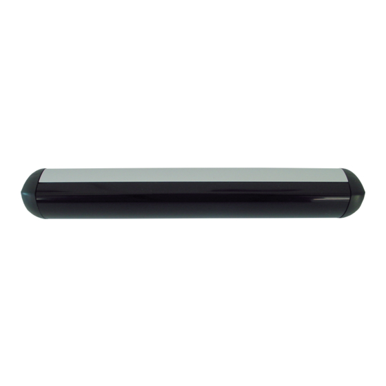
The GC 335 has been designed for detection traveling on the door leaf. The intended use of GC 335 is to secure automatic swinging door in keeping with German standard DIN 18650 / EN 16005. If used as intended, the sensor shall influ-... -
Page 6: Setting The Monitoring Beam - Closing Edge
The transition cable to the door control can be passed through the end cap by means of a cable bushing. If you use the accessories "GC 335 Ergänzungskit IP54", please fix a double-faced scotch tape between the profile and the mounting surface. This avoids the intrusion of water through the drills of the sensor profile. -
Page 7: Optical Setting Of The Sensor
Optical Setting of the Sensor You can swivel the detection field away from the door or towards the door by setting the angle of incli- nation. The angle of inclination can be varied continuously from 0° to + 25°. Use the handle on the chassis metal to set the angle of inclination. For the adjustment of the angle of inclination use the M3 screw (g) at the top of the module holder. -
Page 8: Detection Field
Angle of Inclination of the Sensor: Lay the test card on the ground with the marking parallel to the door. Rest the test specimen to the marking on the side of the door (cf. Figure 3.6). The sensor points down vertically. Use the chassis lever to swivel the sensor forward until it detects the test specimen raised by 20 cm (LED = red). -
Page 9: Master / Slave Operation
Master / Slave Operation Difference between Master and Slave Module It is possible to fit up to seven additional slave modules, apart from one master module. The differences between the master module and the slave module are as follows: Master module: with relay;... -
Page 10: Technical Data / Connection Diagram
< 2 % at a detection range of 2,000 mm Marking CE, TÜV Number of beams Number of sensor modules GC 335 mounted Mode of operation Background evaluation Diameter of the light spot 1,1 cm x 8,3 cm at a detection range of 2 m for each module... -
Page 11: Assignment Of The Connections
• Test input is inactive at:U_low = -3 V ... +5 VDC • Test input is active at: U_high = +11 V ... +24 V DC 20 % ± Components of GC 335 Part Numbers Description 128074 GC 335, MASTERMODUL... - Page 12 E-Mail: finland.se@geze.com 97944 Boxberg-Schweigern www.geze.com Tel. +49 (0) 7930-9294-0 Fax +49 (0) 7930-9294-10 Baltic States Iberia E-Mail: sk.de@geze.com GEZE GmbH Baltic States office GEZE Iberia S.R.L. Scandinavia – Denmark E-Mail: office-latvia@geze.com E-Mail: info@geze.es GEZE Danmark www.geze.com www.geze.es E-Mail: danmark.se@geze.com GEZE GmbH www.geze.dk...


Need help?
Do you have a question about the GC 335 and is the answer not in the manual?
Questions and answers