Fermax VDS Technical Manual
Hide thumbs
Also See for VDS:
- Quick start manual (25 pages) ,
- Advanced programming (4 pages) ,
- Installer manual (36 pages)
Table of Contents
Advertisement
Advertisement
Table of Contents

Subscribe to Our Youtube Channel
Related Manuals for Fermax VDS


Summary of Contents for Fermax VDS
- Page 1 TECHNICAL MANUAL VDS SYSTEM Section I Description of the VDS System...
- Page 2 VDS Technical Manual- Section I Code 97508I-1 V07_09 This technical document of an informative nature is published by FERMAX ELECTRONICA S.A.E., who reserve the right to modify the technical characteristics of the products referred to herein at any time and without prior notice. These changes will be reflected in subsequent editions of this document.
-
Page 3: Table Of Contents
SECTION I - DESCRIPTION OF THE VDS SYSTEM VDS SYSTEM ................................5 - General Features ..............................5 - Basic diagram for a VDS video door entry system ....................7 - The VDS system in REPLACEMENT installations....................8 - VDS System Operating Principles ........................10 - Installation and Start-Up Instructions for VDS systems .................. - Page 4 Page 4 Code 97508I-1 V07_09...
-
Page 5: Vds System
* One or two door entry system or video door entry system access points (entrances) The VDS system enables up to two access points to be installed in the same building, with the possibility of combining audio and video entry devices. - Page 6 * Access Control Accessories The VDS Direct and Digital systems incorporate access control functions using codes input via the panels’ numerical keypad, (previously programmed using the keypad). The VDS Digital systems can also incorporate secondary proximity readers as access controls...
-
Page 7: Basic Diagram For A Vds Video Door Entry System
Basic Diagrams of VDS electronic DOOR ENTRY systems Basic Wiring: 3 wires. 1 Audio Access Point 1 Audio Access Point + Guard Unit Guard Unit Switcher Ref. 2492 VDS Guard Unit Ref. 2536 2 Audio Access Points Code 97508I-1 V07_09... -
Page 8: The Vds System In Replacement Installations
Basic Diagrams of VDS VIDEO DOOR ENTRY systems Basic Wiring: UTP Cat5 / 5 wires/ 3 wires + Coaxial. 1 Video Access Point 1 Video Access Point + Guard Unit (*): UTP Cat5 / 5 wires/ 3 wires + Coaxial... - Page 9 The VDS system in REPLACEMENT systems Given its features and resources the VDS system is the ideal system for the replacement of a door entry system with a video door entry system. Allows the use of the door entry system’s existing wiring to convert it to a digital video door entry system.
-
Page 10: Vds System Operating Principles
The way in which the call is made and the call code generated depends on the type of entry panel: - Button Panels (City): In the case of the button panels, each button corresponds to a particular «VDS call code/address» which means that a call can be made to a residence by pressing the corresponding call button. - Page 11 Activation Commands VDS system terminals include F1 and F2 buttons (present on all «Extra» monitor and telephone models) which allow the user to activate external devices (relays, timers, etc...) to control additional functions: courtesy lighting, secondary doors, garages, etc.
-
Page 12: Installation And Start-Up Instructions For Vds Systems
For replacement systems, it is recommended that the user carries out a prior evaluation of the wiring features so as to be aware of the relevant features and determine if any replacement or reorganisation is necessary. For more information please refer to the section entitled: «The VDS system in REPLACEMENT Installations» in the relevant manual. -
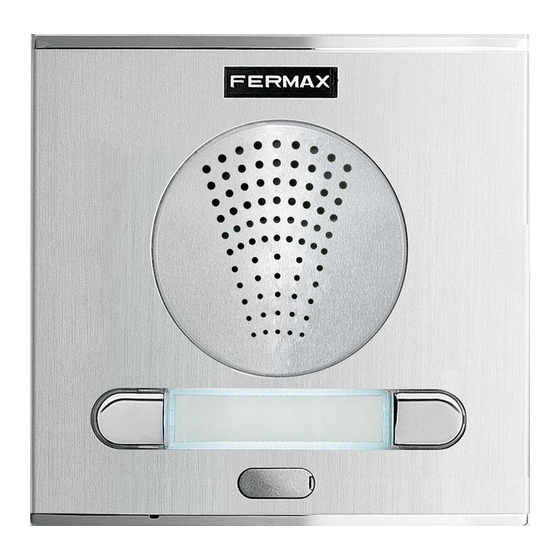
Page 13: Vds Panels
VDS PANELS The VDS audio and video panels are available in the following designs and formats: - Designs: Cityline (continuous profile),Citymax (modular), Halo, Marine and Bruto - Types: City (buttons), Direct (keypad) and Digital (keypad+electronic directory). BUTTONS MODULAR DIRECT DIGITAL... -
Page 14: Vds Amplifier
Amplifier rear view SENSOR TEMP. The Halo Panel and the integrated VDS amplifier in contrast with all other panel versions form a single block which cannot be separated from the rest of the panel’s electronics. Page 14 Code 97508I-1 V07_09... - Page 15 (see the ‘Advanced Programming’ section). Lock Release Times. * Restore default values The VDS amplifier has a ‘Reset’ function which can be used to restore programmed default parameters (door and entrance hall lock-release times, access codes, mapping) (see the «VDS Amplifier - Reset» section).
-
Page 16: New Cityline Panels
VDS Amplifier - New Cityline Panels The VDS amplifier manages all the VDS system functions: calls, two-way communication, door opening, programming..It is available in Audio and Video versions. CN1: Connection for call extension module, keypad, display or up to three buttons (the same amplifier for buildings and kits with up to 3 lines). - Page 17 Diagnostic Led: If there is a short circuit between “L” and “+”, short flashes will be emitted when a call is made from the panel. * Restore factory settings. Reset The VDS amplifier has a ‘Reset’ function which can be used to restore programmed default parameters (door and hall lock-release times, access codes, mapping). - Reset from button panels To restore the default values, follow the steps below: 1.- Reset amplifier: disconnect power supply...
-
Page 18: Cityline, Marine And Bruto Panels
VDS Amplifier - Cityline, Marine and Bruto Panels The VDS amplifier manages all the VDS system functions: calls, two-way communication, door opening, programming..Connection for call extension module, keypad, display or up to three buttons (the same amplifier for buildings and kits with up to 3 lines). -
Page 19: Halo Panels
VDS Amplifier - Halo Panels The VDS amplifier manages all the VDS system functions: calls, two-way communication, door opening, programming..IDIOMA LANGUAGE SENSOR TEMP. Pan & Tilt Camera Adjustment (10º horizontal - vertical). Heat Resistant Connector (optional). ON The camera leds are activated when a call is made Camera Lighting Deactivation/Activation Switch from the panel or auto-started from the residence. -
Page 20: New Cityline Panels
- Call Extension Module (one for every 16 buttons): The main advantage of a VDS panel is that it does not use call wires. This is possible because the call is made through the transmission of a digital code, which is generated via call extension modules (see the ‘Call Extension Module’... -
Page 21: Call Extension Module
* Call extension module, Ref. 2441 One of the advantages of the VDS system is that no call wires are used. This is possible because the call is made through the transmission of a digital code generated by the amplifier in the outdoor entry panel when a specific call button is pressed. -
Page 22: Button Panels. Modular
The button modules are available with 2, 4 and 8 buttons. Calls to residences are made by pressing the corresponding call button assigned to the residence. - Display Module and Direct Keypad: Allows the construction of Direct and Digital VDS modular panels. -
Page 23: Button Module Interconnection
As mentioned above, the modular panels do not require a call extension module, given that the button modules generate the «VDS call code» corresponding to each residence (do not confuse the VDS call code or VDS call address with the residence door no.). -
Page 24: Direct Panels (Keypad)
- Programming the lock-release time between 1 and 99 seconds. * DIRECT VDS panel typology The size of VDS DIRECT panels is always the same (Series 4 or 6 if a recess is included) independently of the number of residences. - Page 25 Programming the lock-release code on Direct Panels All Direct panel models enable the door to be opened from the outdoor entry panel by entering a 4-digit code. The steps to be followed to activate and configure the door lock release using a code are detailed below: * Door lock-release activation sequence.
-
Page 26: Digital Panels (Keypad + Display)
This Directory Panel is optional as its function is already provided by the LCD display. The directory panel is fitted with a set of lamps which must be connected to the VDS amplifier (see internal panel wiring diagrams). - Page 27 Telephone Code search is carried out on the screen and ’ %’ is pressed. Like the rest of the VDS system, the line number must be a value between 001 and 199 and it must have been pre-programmed on the telephone/monitor.
-
Page 28: Vds Guard Unit
VDS Guard Unit Connection Module (Ref. 2492) To install a VDS guard unit in a system with entry panels you require a «VDS guard unit connection module» Ref. 2492. This module allows the user select the active devices and establish communication between them: - Guard Unit <-->... - Page 29 Call/Establish Communication. Press this key to call the residential telephones or establish communication with a selected queued call. For more information on the VDS Central Guard Unit, please consult manual code: - 97001 VDS/ADS Guard Unit Manual. Code 97508I-1 V07_09...
- Page 30 Operating Modes The characteristics of the different operating modes for buildings with one sole Central Guard unit are: DAY MODE * The Central Guard Unit can call and receive calls from the telephones. * The outdoor entry panels cannot call the telephones directly. * The calls from the entry panel to the telephones are intercepted by the Central Guard Unit, who can transfer them to the telephone call or an alternate telephone.
-
Page 31: Basic Vds System Devices
BASIC VDS SYSTEM DEVICES In addition to the entry panels and guard units, the VDS system requires a number of basic devices to complete the system and ensure its correct operation. The functions of each of these devices is detailed below:... -
Page 32: Vds Switcher
It is not necessary in systems in which one of the accesses is audio only. In systems with a guard unit, this switcher is substituted for a «VDS Guard Unit Connection Module» Ref. 2492. Panel Connector 1: «S, +, L, V, M» connection wires from Panel 1. -
Page 33: Video Distributors
Video Distributors (Ref.2448 - 2449) «Video Distributors» are required at all system points where there is video signal bifurcation: branch distribution, residence distribution per floor, etc. There are two distributor models: - Ref. 2448 2 output video distributor. - Ref. 2449 4 output video distributor. * Connections (V,M): Video Input. -
Page 34: Vds System Power Supplies
VDS door entry/video door entry systems. The VDS systems are powered with 18 Vdc, although depending on the system (number of monitors/telephones installed, type of door lock-release used, distance, etc.) the necessary power supply may vary in model and number: - Source Ref. -
Page 35: Lock-Releases: Continuous And Alternating Lock Release Connection
Electric door lock-release The VDS amplifiers have a potential-free relay (C, No, Nc) which enables the use of both continuous and alternating door lock-release mechanisms (maximum 4A). The 12 Vdc door lock-release power supply can be carried through the VDS amplifier (up to a maximum door lock-release consumption of 0.5A). -
Page 36: Accessories For Vds Systems
ACCESSORIES FOR VDS SYSTEMS The VDS systems can be extended with multiple additional functions. The different accessories available for the extension of the VDS system are detailed below. DEVICE FUNCTION Installed in the residence and connected to the telephone, it allows communication with the entry panel and the door be opened from any conventional fixed or wireless telephone. -
Page 37: Residential Terminals
RESIDENTIAL TERMINALS The VDS system has a wide range of residential terminals both for door entry systems (telephones) and video entry systems (monitors). The residential terminals enable the user to establish audio/video communication with the outdoor entry panel, open the door, call the guard unit, etc. -
Page 38: Video Terminals: Vds Monitors
Video terminals: Monitors The VDS monitors should be installed in VDS video systems (with video panels). The video systems can be extended with monitors and/or additional telephones. Fermax offers a wide range of monitors for the VDS system: MONITOR INSTALLATION... -
Page 39: Connectors And Connections
Connectors and Connections The VDS residential terminals (monitors/telephones) are fitted with connectors which are installed in the residence to connect the residential terminal to the system. Depending on the residential terminal model, the connector format will vary, but not the main connection terminals (Bin, Bout, F1, F2, CT, T,...), so that the cabling for the various terminals is carried out following the same connection diagram. -
Page 40: Vds Terminal Programming (Monitors And Telephones)
Loft Compact Monitor, B/W and Colour 3740 - 3753 97093 iLoft VDS Monitor 5610 97315 Manuals available on the Fermax website: www.fermax.com. The technical documentation codes may vary, refer to the Fermax website for the latest versions. Page 40 Code 97508I-1 V07_09... -
Page 41: Advanced Programming
POWER SUPPLY 18 Vdc CN7 VIDEO TEST MONITOR 2. Select the «inverse button programming» mode on the VDS amplifier: Press the SW1 button (a characteristic ‘beep’ will sound from loud speaker 2). 3. Assign the new addresses to each button: 3.1. -
Page 42: Lock-Release Times On Button Panels
ADVANCED PROGRAMMING: Door lock-release times on button panels There are two programmable lock-release activation times: - Lock-release time set from the residence. - Lock-release time set from the exit button (connected to the ‘BS’ and ‘-’ terminals). To programme the activation time follow the steps below: 1. - Page 43 Code 97508I-1 V07_09 Page 43...
Need help?
Do you have a question about the VDS and is the answer not in the manual?
Questions and answers