
Related Manuals for CAS Scale LP Series


Summary of Contents for CAS Scale LP Series
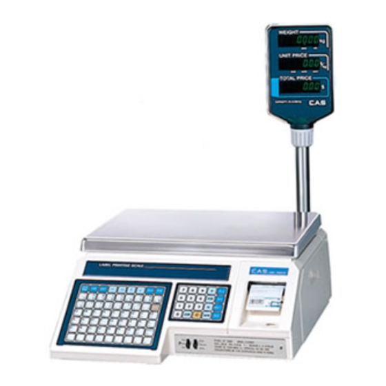
- Page 1 LP series SERVICE MANUAL ( LP-1 ver 1.7 ) THERMAL LABEL PRINTING SCALE S • C • A • L • E...
- Page 2 INDEX 1. BLOCK DIAGRAM 2. CONNECTION DAIGRAM 3. OPENNING THE UNIT 4. SCALE CALIBRATION 5. SCHEMATIC DIAGRAM 6. PCB LAYOUT 7. TROUBLE SHOOTING FLOWCHART 8. PARTS LIST 9. EXPLODED VIEW – UPPER CASE 10. EXPLODED VIEW – BODY 11. SEALING METHOD 12.
-
Page 3: Block Diagram
1. BLOCK DIAGRAM Drawing No.: 9000-L17-0001-0 Step Motor Stepping Motor Driver Data Display Flash Driver Headup Peel Sesor Sensor Sensor 3.6V Battery Regulator Front/Rear KeyBoard Display Interface RS232C Connector Driver ATMEGA103 Switch Load Cell Module Mode Switch Buzzer Reset AC 85V ~ 264V SMPS 220V/3.0A... - Page 4 2. CONNECTION DAIGRAM Drawing No.: 9000-L17-0002-0 220V/5.0A AC 85~264V THERMAL SENSOR HEAD STEPPING NOISE FILTER J13(GAP) MOTOR J14(HEAD UP) J8(PEEL LED) J9(PEEL OPTO) POWER BOARD 6190-PLP-0114-0 (6190-PLP-7040-0) MAIN BOARD CN24 CONVERTER 6191-PLP-0200-0 6144-A00-0065-0 INTERFACE CONNECTOR 25PIN CN21 DISPLAY BOARD 6110-PLP-0236-0 POLE DISPLAY 6110-PLP...
- Page 5 3. OPENNING THE UNIT A. Removing the Display PCB Disconnect AC code. Put the scale where you can reach both the back and the front of it easily. iii. Refer to “12. EXPLODED VIEW – UPPER CASE.” Pull out the tray and the paper cover. On the front side of the upper case are the four screws holding the front cover on.
-
Page 6: Scale Calibration
4. SCALE CALIBRATION A. Description CAL#1 : Shows the span – adusted ADC output. CAL#2 : Key test mode iii. CAL#3 : Span calibration is carried in the mode CAL#4 : Scale Setting mode CAL#5 : Pure ADC output CAL#6 : Printer sensor setting vii. - Page 7 WEIGHT UNIT PRICE $/kg CAL1 8594 It indicates the factored AD value. It indicates the factored raw AD In other words, it shows the value of scale. relative value that the first point of time that you press zero key or you enter the CAL1 mode supposes zero point.
- Page 8 WEIGHT UNIT PRICE $/kg CAL4 It set the capacity of scale. 6kg single 2. 6kg dual 3 : 15kg single 4. 15kg dual 5 : 30kg single 6. 30kg dual WEIGHT UNIT PRICE $/kg CAL5 8594 It indicates raw AD value. In other It indicates raw AD value of scale.
-
Page 9: Schematic Diagram
5. SCHEMATIC DIAGRAM A. Main Board Schematic (a) CPU and Memory Part (Document No: 9000-L17-0003) - Page 10 (b) Power and I/O Part (Document No: 9000-L17-0004)
- Page 11 B. Display Board Schematic (Document No: 9000-L17-0005)
-
Page 12: Pcb Diagram
6. PCB DIAGRAM A. Main PCB Diagram (PCB No.: 6191-PLP-0200-0) (a) Top Part (Document No: 9000-L17-0006) - Page 13 (b) Bottom Part (Document No: 9000-L17-0007)
- Page 14 B. Display PCB Diagram (PCB No.: 6110-PLP-0236-0) (a) Top Part (Document No: 9000-L17-0008)
- Page 15 (b) Bottom Part (Document No: 9000-L17-0009)
-
Page 16: Troubleshooting Flowchart
7. TROUBLE SHOOTING FLOWCHART Drawing No.: 9000-L17-0010-0... -
Page 17: Parts List
8. PARTS LIST A. Main PCB PARTS NAME SPECIFICATION UNIT Q'TY REMARK 6191-PLP-0200-0 6191-PLP-0200-0 IC(CPU) ATMEGA128 6200-IPU-0128-A IC(CPLD) M4A5-32/32-10VC 6216-IS0-0032-0 IC(SRAM) LP621024D-70LL 6202-IS0-6810-0 IC(FLASH MEMORY) SST39SF040-70-4C-WH 6204-IS0-3904-0 U5,6 IC(NV RAM CONTROL) DS1210S/bq2201 (SOIC) 6202-IS0-1210-0 IC(TIMER) DS1302 6228-IS0-1302-0 IC(DRIVER) TD62064BP-1 6224-I00-6264-0 IC(C MOS) 74HC573 6236-IS0-0573-A... -
Page 18: Parts Name
RESISTOR-CHIP-ARRAY RP164P101J(=1608 100Ω X 4PCS) 6598-IJ0-1000-0 RN2,3,4,9,11,12 CONDENSER-CHIP CL21F 104 KBNC 6712-CHP-0104-0 C5,8~11,15~34 CONDENSER-CHIP 105(1uF 0805 type) 6712-CHP-0105-0 C1~4,7 CONDENSER-CHIP CL21B 102 KBNC 6712-CHP-0102-0 C6,14 CONDENSER-CHIP CL21C 200 JBNC(20PF) 6712-CHP-0200-0 C12,13 CONDENSER-ELECTRIC 1000uF/25V 6704-C25-1000-0 CONDENSER-ELECTRIC 470uF/50V 6704-C50-0470-0 CONDENSER-ELECTRIC 100uF/6.8V 6.3 6706-C68-0100-0 DIODE CHIP KDS 160... - Page 19 7 CONDENSER-CHIP CL21F 104 KBNC 6712-CHP-0104-0 C1,C3,C14~C17 8 CONDENSER-ELECTRIC 470uF/25V 6704-C25-0470-0 9 CONDENSER-CERAMIC 0.1uF/25V 6710-CAP-0104-0 10 CONDENSER-CHIP CL21B 102 KBNC 6712-CHP-0102-0 C5 ~C12 11 CONDENSER-CHIP CL21C 200 JBNC(20PF) 6712-CHP-0200-0 12 SOCKET CONNECTOR 5332-20P 7813-C00-0020-0 13 CONNECTOR(WAFER) 5267-02 7805-CCN-6702-0 14 SOCKET CONNECTOR 5332-34P 7813-C00-0034-0 15 CONNECTOR(WAFER)
-
Page 20: Exploded View
9. EXPLODED VIEW A. Upper Case (Drawing No.: 3003-LPR-0001-1) - Page 21 B. Body(Drawing No.: 3002-LPR-0000-2)
- Page 22 C. Printer Mechanism (Drawing No.: 3004-LPR-0000-1)
-
Page 23: Sealing Method
10. SEALING METHOD A. Sealing #1 (Drawing No.: 3005-LP0-0000-0) - Page 24 B. Sealing #2 (Drawing No.: 3005-LP0-0000-0)
-
Page 25: Interface List
11. INTERFACE LIST A. RS232c(Drawing No: 9000-L17-0011-0) DB9 Female DB25 Female Scale Title LP-1(ver 1.7) RS232c INTERFACE DIAGRAM Document Number 9000-L17-0011 Date:... - Page 26 12. LOAD CELL DIAGRAM Drawing No: BC5AS-201-00)...
-
Page 27: Smps Specification
13. SMPS SPECIFICATION A. SMPS(6190-PLP-0114-0) PCB Diagram(Drawing No: 9000-L16-0009-0) Title SMPS PCB DIAGRAM(1104) Document Number 9000-L16-0009 Date:... - Page 28 Part List PARTS NAME SPECIFICATION UNIT Q'TY REMARK POWER PCB 6190-PLP-0114 IC PWM 3844 IC REGULATOR 7805 IC21 IC REGULATOR 7912 IC23 IC SHUNT IC22 PHOTO COUPLER PC-17T1, KP1010A 2SK1537, STHV82, NTK9005, SSH6N80A(FQA6N80), SSH9N80A TIP41C, 2SD613E 3203 10 DIODE BRIDGE D3SB(A)60, 406 11 DIODE SCHOTTKY RK39, 31DQ09...
- Page 29 50V 47uF M pi6.3X11 22 CAPACITOR ELECT C11,C31,C32 (85Degree) 25V 100uF M pi6.3X11 23 CAPACITOR ELECT C25,C26 (85Degree) 50V 0.33uF M pi5X11 24 CAPACITOR ELECT (85Degree) 25 CAPACITOR CERAMIC NU250VAC 222M Y2 C2,C3 26 CAPACITOR CERAMIC CKF103Z 1KV 0.01uF DH222M 250VAC 0.0022uF, 27 CAPACITOR CERAMIC DE222M, AD222M, SC222M 28 CAPACITOR CERAMIC...
- Page 30 49 RESISTOR CARBON 1/4W 22 kOhm J 50 RESISTOR CARBON 1/4W 2.7 kOhm J 51 RESISTOR CARBON 1/4W 12 kOhm J 52 RESISTOR CARBON 1/4W 24 Ohm J 53 RESISTOR CARBON 1/4W 470 Ohm J 54 RESISTOR CARBON 1/4W 24 kOhm J 55 RESISTOR CARBON 1/4W 47 kOhm J 56 RESISTOR CARBON...
- Page 31 B. SMPS(6190-PLP-7040-0) PCB Diagram(Drawing No: 9000-L16-0010-0) Title SMPS PCB DIAGRAM(7040) Document Number 9000-L16-0010 Date:...
-
Page 32: Specification
Part List PARTS NAME SPECIFICATION UNIT Q'TY REMARK 6190PLP70400 3842 IC21 7805 IC22 7812 IC23 PHOTO COUPLER 621, 817 TRANSISTOR 3203 TR22 BRIDGE DIODE D3SBA60, GBU4J DIODE / FRD UF4007, UF1010 10 DIODE / FRD UF4004, UF104 D3, 23, 24 11 DIODE / FRD S3L20U 12 DIODE / FRD... - Page 33 CR, 1/6W, J 23 RESISTOR R37, 38 1K, 5% CR, 1/6W, J 24 RESISTOR 4.7K, 5% CR, 1/6W, J 25 RESISTOR R8, R29 7.5K, 5% CR, 1/6W, J 26 RESISTOR R7, 39 10K, 5% CR, 1/6W, J 27 RESISTOR 47K, 5% MR, 1/6W, F 28 RESISTOR R9, R16...
- Page 34 MOR, 2W, J 39 RESISTOR 1K, 5% MOR, 2W, J 40 RESISTOR 2.7K, 5% MOR, 2W, J 41 RESISTOR R12, 14 51K, 5% MOR, 2W, J 42 RESISTOR 68K, 5% KMG 50V 47uF, KME1H470MTD04R 43 ELEC/CAP C12, 23, 26 50V/47uF 6.3 X 11 KMG 63V 47uF, KME 63V 47uF 44 ELEC/CAP 63V/47uF 6.3 X 11...
- Page 35 TY2A223JAN 55 FILM/CAP 100V/0.022uF, J TY2A153KAN 56 FILM/CAP 100V/0.015uF, K TY2A102KAN 57 FILM/CAP C9, 39 100V/0.001uF, K TM2J103KAM 58 FILM/CAP 630V/0.01uF ECQV1H104JL, PCMT36575104 59 FILM/CAP C10, 27 0.1uF/50V, 0.1uF/63V ECQV1H224JL, PCMT36575224 60 FILM/CAP 0.22uF/50V, 0.22uF/63V KNB1530-104M, PCX2335M1104 61 FILM/CAP 275VAC/0.1uF KNB1530-224M, PCX2 335 M1224 62 FILM/CAP 275VAC/0.22uF...
Need help?
Do you have a question about the LP Series and is the answer not in the manual?
Questions and answers