Advertisement
Quick Links
Advertisement

Subscribe to Our Youtube Channel
Related Manuals for Novus NMS NVR M5


Summary of Contents for Novus NMS NVR M5
- Page 1 ’s m a n u a l NMS NVR M5 NMS NVR M7...
-
Page 2: Important Safeguards And Warnings
NMS NVR M5, NMS NVR M7 User’s manual ver.1.0 IMPORTANT SAFEGUARDS AND WARNINGS EMC (2004/108/EC) and LVD (2006/95/EC ) Directives CE Marking Our products are manufactured to comply with requirements of following directives and national regulations implementing the directives: ... - Page 3 11. You cannot allow any metal objects get inside the recorder. It might cause serious damage. If a metal object gets inside the device contact the authorised Novus service immediately. 12. The manufacturer does not bear responsibility for damage or loss of data stored on HDDs or other media occurred during the usage of the product.
-
Page 4: Foreword Information
NMS NVR M5, NMS NVR M7 User’s manual ver.1.0 FOREWORD INFORMATION 1. PACKAGE CONTENTS Unpack the device carefully. After unpacking, please ensure that package contains the following items: Network Video Recorder Power ignition module Power cord (power ignition module - NVR) ... -
Page 5: Technical Data
NMS NVR M5, NMS NVR M7 User’s manual ver.1.0 FOREWORD INFORMATION 3. TECHNICAL DATA NMS NVR M7 NMS NVR M7 Video IP Cameras 16 channels at 1280 x 720 resolution (video + audio) Supported Cameras/Protocols NOVUS, RTSP Supported Resolution max. 2592 x 1944 Compression H.264, MJPEG... - Page 6 NMS NVR M5, NMS NVR M7 User’s manual ver.1.0 FOREWORD INFORMATION 3.1. Dimensions All dimensions are in mm. All rights reserved © AAT HOLDING S.A.
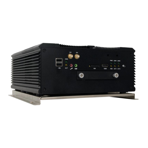
- Page 7 NMS NVR M5, NMS NVR M7 User’s manual ver.1.0 FOREWORD INFORMATION 3.2. Front and backpanel connectors Antenna connectors (for optional card) HDMI port USB Ports Power LED Ethernet LED Power button Audio input Audio output 2,5” HDD mounting HDD LED...
-
Page 8: Starting The Device
NMS NVR M5, NMS NVR M7 User’s manual ver.1.0 STARTING THE DEVICE 4. DEVICE INSTALLATION Please familiar with the product, its parameters, and the installation process before installation. Device mounting is realized by screwing the antivibration kit to ground. NVR should be placed on the flat surface. - Page 9 NMS NVR M5, NMS NVR M7 User’s manual ver.1.0 STARTING THE DEVICE Connection sheme is shown below: Battery Ignition ACC IN DC INPUT Connect the power source (battery) and ignition ACC IN signal to DC Input. The minimal recommended cable diameter (not including insulation) is 2.59 mm (10 AWG). The maximal recommended cable length is 3 meters.
- Page 10 NMS NVR M5, NMS NVR M7 User’s manual ver.1.0 STARTING THE DEVICE DC OUTPUT DC OUTPUT Ground Ground 6 5 4 3 2 Reserved Reserved Power connector of the NMS NVR M DC IN 9V-30V 1 V+ 2 V+ 3 Ground...
- Page 11 NMS NVR M5, NMS NVR M7 User’s manual ver.1.0 STARTING THE DEVICE Switches (SW1 and SW2) located on power ignition module are responsible for working parameters. Switch SW1 is responsible for power on / off voltage level. For 12V DC power supply (SW1: DIP Switch#1, Dip Switch#2):...
- Page 12 NMS NVR M5, NMS NVR M7 User’s manual ver.1.0 STARTING THE DEVICE Selection of the output voltage (SW1: DIP Switch#7, Dip Switch#8): DIP Switch 7 DIP Switch 8 Output Voltage Remarks 0=off 0=off Default 0=off 1=on 1=on 0=off 1=on 1=on...
-
Page 13: First Launch
NMS NVR M5, NMS NVR M7 User’s manual ver.1.0 STARTING THE DEVICE 6. RUNNING THE NVR After installation process, the device can be started. Press the power button to start the NVR or wait for start caused by power ignition module. - Page 14 NMS NVR M5, NMS NVR M7 User’s manual ver.1.0 NVR MENU Main screen will be displayed, and login window to NMS application (Novus Management System), which is is a professional solution for video monitoring based on TCP/IP CLIENT-SERVER networks. (full description in chapter 9.1).
-
Page 15: Main Screen
NMS NVR M5, NMS NVR M7 User’s manual ver.1.0 NVR MENU From the NMS Management list choose the Language. It displays the list with available languages. Choose the prefered one and confirm by clicking OK. Changing the language on the main screen will be applied immediately. Changing the language in the NMS will be introduced after the restarted of the application or the NVR. - Page 16 NVR MENU 9.1. Menu - NMS Selecting NMS on the main screen launches the NMS (Novus Management System) application which is is a professional solution for video monitoring based on TCP/IP CLIENT-SERVER networks. A wide range of NMS server settings for video streams sharing enables creation of complex monitoring systems with multi-site recording and surveillance centres, containing many personalised operator stations.
- Page 17 NMS NVR M5, NMS NVR M7 User’s manual ver.1.0 NVR MENU 9.1.1. Starting the NMS NMS application start along with the the operating system . Initialisation of the modules is processed. However, until the log in NMS is working in background. At the bottom of the main screen there is a field indicating the status of NMS.
- Page 18 NMS NVR M5, NMS NVR M7 User’s manual ver.1.0 NVR MENU 9.1.2. NMS setup wizard An embedded NMS Wizard is automatically started when running NMS for the first time. Startup window is depicted below: Checking „Show at start-up” launches wizard every time the NMS is started. In order to move to the next window, please press the „Next”...
- Page 19 NMS NVR M5, NMS NVR M7 User’s manual ver.1.0 NVR MENU This window starts immediate search of: IP cameras by NMS Server and NMS Server/Client device NMS Servers by NMS Client device. All IP cameras and NMS Servers must reside in the same subnet as the host computer. Search is automatic and, when finished, displays a list of available supported devices together with their IP addresses and names.
- Page 20 NMS NVR M5, NMS NVR M7 User’s manual ver.1.0 NVR MENU Entering required data (login and password) and pressing the “Add” button moves an edited account to the “Added” box. When an incorrect user entry has been performed, an account may be deleted by pressing the “Delete”...
- Page 21 NMS NVR M5, NMS NVR M7 User’s manual ver.1.0 NVR MENU Application Live video and Devices and cameras Application menu module icons playback panel panel Video records PTZ panel Logs panel playback 9.1.4. VIDEO panel - information NMS application was developed to support 4 video windows. Each of them can display up to 36 video streams (NMS Server is limiter to display up to 4 streams per window).
- Page 22 NMS NVR M5, NMS NVR M7 User’s manual ver.1.0 NVR MENU Displaying mode in full screen mode or 4, 9, 16, 25, 36 division NMS Server is limited to display up to 4 video streams. Custom screen divisions Previous group of cameras (e.g. when division 2. 3x3 is displayed on the screen it switches to division 3.
- Page 23 NMS NVR M5, NMS NVR M7 User’s manual ver.1.0 NVR MENU Camera status and events icons Playback mode Video recording (according to the schedule or panic recording) Motion detection PTZ control on Related alarm input on Related alarm output on 9.1.5.
- Page 24 NMS NVR M5, NMS NVR M7 User’s manual ver.1.0 NVR MENU after clicking on button the following icon Pop-up window displayed Name, state and description of the video server and cameras Camera status icons: Icon Description IP Device connected IP Device disconnected Schedule or panic recording is enabled/disabled.
- Page 25 NMS NVR M5, NMS NVR M7 User’s manual ver.1.0 NVR MENU The following important messages can be also displayed in device panel: Connecting... - NMS software is trying to establish connection with IP device; Connection lost - lack of communication between IP device and a computer with NMS;...
- Page 26 NMS NVR M5, NMS NVR M7 User’s manual ver.1.0 NVR MENU 9.1.6. Displaying video streams from devices The device panel allows user to display selected video stream in desired window by clicking RMB and choosing Show position in menu. Position “1: - - - “ means, that first screen in division isn’t displaying any video stream at the moment.
- Page 27 NMS NVR M5, NMS NVR M7 User’s manual ver.1.0 NVR MENU The 'drag & drop' method allows to start displaying many video streams simultaneously. In order to do that, please select video streams by holding Ctrl key and clicking LMB on desired streams.
- Page 28 NMS NVR M5, NMS NVR M7 User’s manual ver.1.0 NVR MENU 9.2. Menu - Watchdog Selecting the Watchdog on the main menu displays a Nwatch window. It is a diagnostic application monitoring the performance of the NMS. It contains information about CPU usage, number of threads, used memory, application state and log list.
- Page 29 IPTool - utility to find cameras and change their network parameters. Remote support - runs Team Viewer application. In order to get the remote support contact the Novus technical support department and give the ID and password displayed. Help - displays full version of the NMS user manual.
- Page 30 NMS NVR M5, NMS NVR M7 User’s manual ver.1.0 NVR MENU Disk management - runs tool for HDD management, creating partitions and volumes. System events - starts the Microsoft Management Console (MMC), which contains administrative tools that you can use to manage networks, computers, services, and other system components.
- Page 31 NMS NVR M5, NMS NVR M7 User’s manual ver.1.0 NVR MENU 9.4.2. Screen resolution changing In order to change the screen resolution select the Control panel from the System configuration submenu. In Display (1) panel , press the Adjust resolution (2). In window Screen Resolution choose desired screen (3).
- Page 32 NMS NVR M5, NMS NVR M7 User’s manual ver.1.0 NVR MENU 9.5. Shutdown the device NMS NVR can be turned off in several ways. Press the power button located on the front panel (marked no.3 on the photo in chapter 3.2. of this manual).
- Page 33 NMS NVR M5, NMS NVR M7 User’s manual ver.1.0 NOTES All rights reserved © AAT HOLDING S.A.
- Page 34 2015-12-11 JM, MK AAT Holding sp. z o.o., 431 Pulawska St., 02-801 Warsaw, Poland tel.: +4822 546 07 00, fax: +4822 546 07 59 www.novuscctv.com...
Need help?
Do you have a question about the NMS NVR M5 and is the answer not in the manual?
Questions and answers