Table of Contents
Advertisement
Quick Links
Advertisement
Table of Contents

Related Manuals for Novus DIGIGATE PROFIBUS


Summary of Contents for Novus DIGIGATE PROFIBUS
- Page 1 DIGIGATE PROFIBUS USER GUIDE V1.0x G...
-
Page 2: Table Of Contents
COMMUNICATION AND STATUS LEDS ..............................10 OPERATING PRINCIPLE .................................... 10 6.3.1 MODBUS CONFIGURATION ................................11 6.3.2 PROFIBUS CONFIGURATION ................................11 DATA EXCHANGE TABLES ..................................11 6.4.1 READING TABLE ....................................11 6.4.2 WRITING TABLE ....................................13 6.4.3 USAGE TIPS......................................14 WARRANTY ........................................ 15 NOVUS AUTOMATION 2/15... -
Page 3: Safety Alerts
All safety recommendations appearing in this manual must be followed to ensure personal safety and prevent damage to the instrument or system. If the instrument is used in a manner other than that specified in this manual, the device’s safety protections may not be effective. NOVUS AUTOMATION 3/15... -
Page 4: Introduction
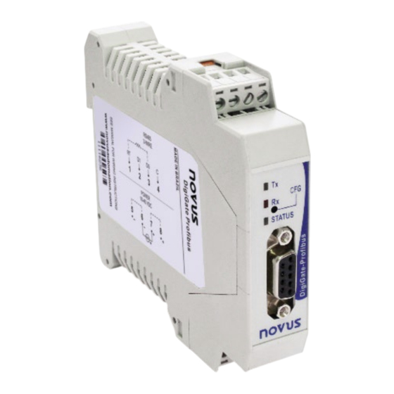
INTRODUCTION DigiGate Profibus is the ideal device for interconnecting a Profibus DP V1 network with a Modbus RTU network. It acts as a Gateway, behaving like a master station on the Modbus network and a slave station on the Profibus network. Thus, depending on its configuration, the DigiGate Profibus will read the data from the other devices (slaves) on the Modbus network and pass the read values on to the Profibus master. -
Page 5: Specifications
03 – Read Holding Register o 04 – Read Input Register Commands available for writing data: • o 05 – Force Single Coil o 06 – Preset Single Register o 15 – Force Multiple Coils o 16 – Preset Multiple Registers NOVUS AUTOMATION 5/15... -
Page 6: Installation
For direct wire connection, the minimum recommended gauge is 0.13 mm² (26 AWG). It must not exceed 4.00 mm² (12 AWG). Be careful when connecting the power terminals to the DigiGate Profibus. If the positive lead of the power supply is connected (even momentarily) to any of the other terminals, the device could be damaged. -
Page 7: Db9 Connector
B / D1 / D+ / D Positive Tx/Rx data (RS485) Request to send Ground from Profibus bus (isolated) +5 V +5 Vdc from Profibus bus (isolated) A / D0 / D- / D\ Negative Tx/Rx data (RS485) Figure 3 Table 1 NOVUS AUTOMATION 7/15... -
Page 8: Configuration
CONFIGURATION It is possible to use the DigiConfig software to configure the DigiGate Profibus via Modbus interface. The device must be put into Configuration Mode. In this mode, the device stops behaving like a master on the Modbus network and starts behaving like a slave, in order to accept commands from the configuration software, which becomes the master. -
Page 9: Operation
J4, J5 and J6 (Profibus terminations) are on the left. The “open” jumper is always in the upper position. JUMPER JUMPER Figure 5 The resistors are factory disconnected (open jumpers) on both the Profibus and Modbus buses. To operate them, the device must be disconnected. NOVUS AUTOMATION 9/15... -
Page 10: Communication And Status Leds
COMMUNICATION AND STATUS LEDS DigiGate Profibus has the following LEDs: DESCRIPTION Signals that the device is sending data via the Modbus RTU network. Signals that the device is receiving data via the Modbus RTU network. Status When permanently lit, this means that the device is connected to the Profibus network (normal operation). -
Page 11: Modbus Configuration
6.4.1 READING TABLE Figure 8 The Reading Table or Input Table contains the values read from the Modbus network device registers (depending on the device configuration), as well as a status register (1st position in the table). NOVUS AUTOMATION 11/15... - Page 12 Bit 7 to Bit 0 – AN7 to AN0 (Adress/Number): Address of the failed slave (if there is only 1 slave that has failed) or number of failed slaves. • The initial state of all bits in the status register is 0. NOVUS AUTOMATION 12/15...
-
Page 13: Writing Table
Bit 9, Bit 8 – RCD1, RCD0 (Request connect/disconnect): A block disconnected by the user remains disconnected until a request to • reconnect the block is sent or the DigiGate Profibus is rebooted. Disconnection or reconnection request: Will be executed via a write request through WD (has higher priority than table writes). -
Page 14: Usage Tips
After connecting to the Profibus network, make sure that the first write is to the entire output table (WT1 = 0 and WT0 = 0). • The safest way to ensure that a writing has been done correctly is to check the registers after the process. • NOVUS AUTOMATION 14/15... -
Page 15: Warranty
WARRANTY Warranty conditions are available on our website www.novusautomation.com/warranty. NOVUS AUTOMATION 15/15...
Need help?
Do you have a question about the DIGIGATE PROFIBUS and is the answer not in the manual?
Questions and answers